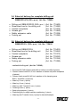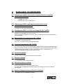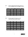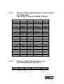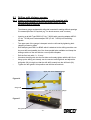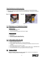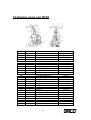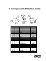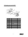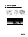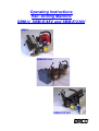
1
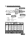
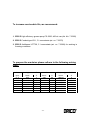
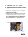
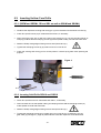
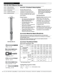
Operating Instructions Rail- Drilling Machine SBM-V, SBM-E/48V and SBM-E/230V SBM-V SBM-E/48 Volt SBM-E/230 Volt ERICO offers the technology for a universally applicable rails drilling technique for · Carrying out drilling for railways and rail tracks · for the ERICO-rails-contact systems SK and DSK · for the areas of guidance and safety technology and · for other sectors in the railway building industry ERICO rail drilling technology distinguishes itself because of the following characteristics: · · · · · · · · · · · · · · · · Light, easy to handle and compact drilling machines with a choice of the following drive motors Two-stroke petrol engine with a spindle speed of 267 r.p.m. for the Æ-range up to 24 mm and a slow drill with a spindle speed of 212 r.p.m. for drill holes with a Æ ³ 24. Direct-current disc drive engine of 48 volt DC 0,62 kW, battery powered with a spindle speed of 391 r.p.m. Alternating current motor of 230V/AC, 1,5 kW with a spindle speed of 220 or 280 r.p.m. Short drilling times because of spindle speeds adapted to each drill diameter. Compact storage of the drilling tools in transportable metal cases. Simple, safe and fast installation of the machine on the rails with quick loosening devices BSK1 and BSK2 Drilling unit can remain fixed to the rail by means of rail foot clamping unit BSF while rail traffic is being maintained. Easily changeable rail profile templates for all rail track profiles. Special templates for special uses, e.g. hinged profiles for grooved rails. Use of universal templates for several rail profiles, e.g. for Germany S49 S 54 UIC 60 Drilling holes at exact intervals with drilling gauges and special templates for axle counters, Fishplates and insulated rail joints. Encompassing drilling program for all applications in the rail sector with the internationally accepted standard tool holding fixture Weldon 19 Extensive range of accessories Extensive range of services Training possibilities by our specialised service personnel. -2- Contents 1 Technical data for ERICO SBM-drilling machines 1.1 Rail drilling machine type SBM-V 1.2 Technical data for Rail drilling machine type SBM-E-48 Volt DC 1.3 Technical data for rail drilling machine type SBM-E-230 Volt AC 2 Safety Instructions 3 Extent of delivery for complete drilling units 3.1 Drilling unit SBM-VS 3.2 Extent of delivery for complete drilling unit SBM-VL 3.3 Extent of delivery for complete drilling unit SBM-E48V-DC 3.4 Extent of delivery for complete drilling unit SBM-E230-AC 4 Available accessories 4.1 Clamping arm BSK1 with Quick-Loosening Device for Vignoles Rails 4.2 Clamping arm BSK2 with Quick-Loosening Device for grooved Rail 4.3 Clamping arm BSF 1 for Rail Foot Fixing 4.4 Metal Box for Accessories 4.5 Universal Template 4.6 Special Templates 4.7 Distance Gauges 4.8 Rail Drills with accessories 4.9 Distance Gauges and special Profile Templates 5 Delivery program rail drills 5.1 SBPM or SBPML high performance hollow core drills: 5.2 SB or SBL disposable hollow core drills: 5.3 SBV 19 high performance solid drills: Triple cutting action 5.4 SBHM or SBHML hollow core drills (hard metal tipped) 5.5 Delivery program double cutting twist drill type SSB 6 Preparing the drilling unit for drilling 6.1 Extending the Drill Spindle to its Final Position for Changing the Drill 6.2 Inserting Hollow Core Drills 6.2.1 (SBPM and SBPML, SB and SBL as well as SBHM and SBHML) 6.2.2 Inserting Solid Drills SBV19 and SSB19 6.2.3 Inserting Twist Drills SSB Ø8 to Ø18 6.3 Connecting the Coolant Receptacle 6.3.1 Setting the Coolant Receptacle into Operation 6.3.2 External tool Cooling -3- 5 5 6 7 8 9 9 10 11 12 13 13 13 13 13 13 13 13 13 13 14 14 14 14 14 17 19 19 20 20 20 21 22 23 24 Contents 7 Attaching the Machine to the Track 7.1 Mounting the Clamping Arms BSK 1 and BSK 2 to the Drilling Machine 7.2 Correct mounting position of the clamping wheels 7.3 Adjusting the Universal Profile Template 7.4 Mounting the Rail Profile Templates 7.5 Attaching the Completely Prepared Drilling Unit to the Rail . 7.5.1 Mounting the Clamping Arm BSF 1 25 25 26 27 28 29 29 7.5.2.Mounting the Rail Profile Template to the Rail Foot Fastening Device BSF1 29 7.5.3 Mounting the Rail Foot Fastening Device BSF 1 to the Drilling Machine 7.5.4 Attaching the Prepared Drilling Unit to the Rail 8 Starting the Engine 8.1 Starting the engine for drilling machine type SBM-V 8.2 Starting the battery operated drilling machine SBM-E/48V 8.2.1 When the machine does not start 8.2.2 Charging the battery pack 9 Drilling 9.1 Drilling with distance gauges 9.1.1 Distance Gauge with Drill Guide and profile template 9.1.2 Distance Gauge without Drill Guide 9.1.3 Allocation of special profile templates 9.1.4 Other profile templates and distance gauges 10 Storage 11 Maintenance 11.1 Maintenance of Gear 11.2 Maintenance of Combustion Engine 11.3 If the engine does not start 12 Spare Parts 13 Putting out of Action / Disposal 14 Drawing spare part BSK1 15 Drawing spare parts BSK 2 16 Drawing spare parts BSF 1 17 Spare parts for SBM-V 17.1 Spare parts for SBM-V with combustion engine 17.2 Spare parts for drive SBM-E/48 Volt DC 17.3 Spare parts for drive SBM-E/230 Volt AC 18 Spare parts for SBM drill units 18.1 Spare parts for drill unit SBM-V 18.2 Spare parts for drill unit SBM-E 48 V 18.3 Spare parts for drill unit SBM-E 230V 19 Warranty 30 30 31 33 33 33 34 35 36 36 37 38 38 39 39 39 40 40 40 41 42 43 44 45 45 46 47 48 48 49 50 51 -4- 1 TECHNICAL DATA for ERICO SBM-drilling machines 1.1 Rail drilling machine type SBM-V 0D[GULOOGLDPHWHU PPKROORZFRUHGULOO 7RROKROGLQJIL[WXUH :HOGRQVKDIWPP 0D[IHHG PP 6SLQGOHVSHHG USPIRUGULOOGLDPHWHUVXSWRPP USPIRUGULOOGLDPHWHUVIURPWRPP 7RROFRROLQJV\VWHP ,QWHUQDOWRROFRROLQJV\VWHPIRUKROORZFRUHGULOOVZLWKDXWRPDWLFFRRODQW YDOYHRSHQLQJ 'ULYH 7ZRVWURNHHQJLQH 3RZHU N:ZLWKUSP 3LVWRQGLVSODFHPHQW FP 6WDUWHU 6WDUWHUFRUG &OXWFK $XWRPFHQWULIXJDOFOXWFK )XHO PL[WXUH 7DQNYROXPH O &RQVXPSWLRQ DERXWJK *HDURLO 6$(:$3,*/ *HDUYROXPH PO /HQJWK PP +HLJKW PP :LGWK PP :HLJKWZLWKRXWIDVWHQLQJGHYLFH DSSUR[NJ 5DLOKHDGIDVWHQLQJGHYLFHIRU 9LJQROHVUDLOV%6. DSSUR[NJ $UW1R 5DLOKHDGIDVWHQLQJGHYLFHIRU JURRYHGUDLOV%6. DSSUR[NJ $UW1R 5DLOIRRWIDVWHQLQJGHYLFHIRU 9LJQROHVUDLOV%6) DSSUR[NJ $UW1R 7HPSODWHV * $YDLODEOHIRUDOOFRPPRQUDLOW\SHV Not included in the extent of delivery for SBM-V machines. -5- 1.2 Technical data for Rail drilling machine type SBM-E-48 Volt DC 0D[GULOOGLDPHWHU 7RROKROGLQJIL[WXUH 0D[IHHG 6SLQGOHVSHHG PPKROORZFRUHGULOO :HOGRQVKDIWPP PP USPIRUGULOOGLDPHWHUVXSWRPP 7RROFRROLQJV\VWHP ,QWHUQDOWRROFRROLQJV\VWHPIRUKROORZFRUHGULOOVZLWKDXWRPDWLF FRRODQWYDOYHRSHQLQJ 'LUHFWFXUUHQWGLVFGULYHHQJLQH N:ZLWKUSP 9ROW'& 6$(:$3,*/ PO PP PP PP 'ULYH 3RZHU 9ROWDJH *HDURLO *HDUYROXPH /HQJWK +HLJKW :LGWK %DWWHU\SDFN(1R :HLJKWEDWWHU\SDFN &KDUJLQJGHYLFH(1R :HLJKWFKDUJLQJGHYLFH :HLJKWZLWKRXWIDVWHQLQJGHYLFH 5DLOKHDGIDVWHQLQJGHYLFHIRU 9LJQROHVUDLOV%6. $UW1R 9ROW$PSKRXUV NJ 9ROW$PSFKDUJLQJFXUUHQW±,3 $SSUR[NJ $SSUR[NJ DSSUR[NJ 5DLOKHDGIDVWHQLQJGHYLFHIRU JURRYHGUDLOV%6. $UW1R DSSUR[NJ 5DLOIRRWIDVWHQLQJGHYLFHIRU 9LJQROHVUDLOV%6) $UW1R 7HPSODWHV DSSUR[NJ $YDLODEOHIRUDOOFRPPRQUDLOW\SHV * Not included in the extent of delivery for SBM-E 48 Volt DC machines. -6- 1.3 Technical data for rail drilling machine type SBM-E-230 Volt AC 0D[GULOOGLDPHWHU PPKROORZFRUHGULOO 7RROKROGLQJIL[WXUH :HOGRQVKDIWPP 0D[IHHG PP 6SLQGOHVSHHG USPIRUGULOOGLDPHWHUVXSWRPP USPIRUGULOOGLDPHWHUVIURPWRPP 7RROFRROLQJV\VWHP ,QWHUQDOWRROFRROLQJV\VWHPIRUKROORZFRUHGULOOVZLWKDXWRPDWLFFRRODQWYDOYH RSHQLQJ 'ULYH $OWHUQDWLQJFXUUHQWHQJLQH 3RZHU N: 9ROWDJH 9ROW$& *HDURLO 6$(:$3,*/ *HDUYROXPH PO /HQJWK PP +HLJKW PP :LGWK PP :HLJKWZLWKRXWIDVWHQLQJGHYLFH DERXWNJ 5DLOKHDGIDVWHQLQJGHYLFHIRU 9LJQROHVUDLOV%6.$UW1R DSSUR[NJ 5DLOKHDGIDVWHQLQJGHYLFHIRU JURRYHGUDLOV%6.$UW1R DSSUR[NJ 5DLOIRRWIDVWHQLQJGHYLFHIRU 9LJQROHVUDLOV%6)$UW1R DSSUR[NJ 7HPSODWHV $YDLODEOHIRUDOOFRPPRQUDLOW\SHV * Not included in the extent of delivery for SBM-E 230 Volt machine -7- 2 Safety Instructions · Read the Operating Instructions prior to starting up the machine! · Keep these Operating Instructions with the machine during its complete serviceable life! · Use the drilling machine according to its proper purpose only! · It is imperative to observe the rules for prevention of accidents when working on railway lines being in use! · Wear safety glasses! · Wear work gloves! · Tie long hair together! · Wear a hairnet to protect very long hair! · Wear safety boots! · Take jewellery off prior to starting work! · Do not put your hands into running tools! · The employer is obliged to have made the Operating Instructions accessible to the user and has to make sure that the user has read and understood them. Symbols Technical instructions for application Please observe them strictly to avoid damage to the appliance. Technical instructions for safety. Please observe them strictly to avoid personal injury and damage to the environment. -8- 3 Extent of delivery for complete drilling units 3.1 Drilling unit SBM-VS (Art. No. 715685) · · · · · Drilling unit SBM-VS (267 r.p.m.) Sheet steel box for the drilling unit Coolant receptacle Grease gun Tooling set, (Art. No. 715462) (Art. No. 715695) (Art. No. 715375) (Art. No. 715830) (Art. No. 715395) contents tooling set (Art. No. 715395) : Þ Set screw M 10x8 to fasten twist drills or hollow core drills (4 pieces) Þ Cheese head screw M 6x16 incl. Washers to fasten rail profile templates (4 pieces) Þ Cheese head screw M 8x20 incl. washers to fix clamping arms BSK 1 and BSK 2 (4 pieces) Þ Allan key 5 mm (1 piece) Þ Allan key 6 mm (1 piece) Þ Allan key with T-handle 5 mm (1 piece) Þ Cleaning brush (1 piece) Þ Spark plug spanner (1 piece) Þ Positioning pin for slight machine positioning (1 piece) Þ Allan key with T-handle 4 mm (1 piece) for twist drill adapter -9- 3.2 Extent of delivery for complete drilling unit SBM-VL (Art. No. 715460) · · · · · Drilling unit SBM-VL (212 r.p.m.) Sheet steel box for the drilling unit Coolant receptacle Grease gun Tooling set, (Art. No. 715461) (Art. No. 715695) (Art. No. 715375) (Art. No. 715830) (Art. No. 715395) contents tooling set (Art. No. 715395) : Þ Set screw M 10x8 to fasten twist drills or hollow core drills (4 pieces) Þ Cheese head screw M 6x16 incl. Washers to fasten rail profile templates (4 pieces) Þ Cheese head screw M 8x20 incl. washers to fix clamping arms BSK 1 and BSK 2 (4 pieces) Þ Allan key 5 mm (1 piece) Þ Allan key 6 mm (1 piece) Þ Allan key with T-handle 5 mm (1 piece) Þ Cleaning brush (1 piece) Þ Spark plug spanner (1 piece) Þ Positioning pin for slight machine positioning (1 piece) Þ Allan key with T-handle 4 mm (1 piece) for twist drill adapter - 10 - 3.3 Extent of delivery for complete drilling unit SBM-E48V-DC (Art. No. 715400) · · · · · · · Drilling unit SBM-E/48V (391 r.p.m.) Sheet steel box for the drilling unit Battery pack 48 Volt / 7.2 Ah Battery charger 48 Volt / 1A Coolant receptacle Grease gun Tooling set, (Art. No. 715356) (Art. No. 715695) (Art. No. 715357) (Art. No. 715425) (Art. No. 715375) (Art. No. 715830) (Art. No. 715395) contents tooling set (Art. No. 715395) : Þ Set screw M 10x8 to fasten twist drills or hollow core drills (4 pieces) Þ Cheese head screw M 6x16 incl. washers to fasten rail profile templates (4 pieces) Þ Cheese head screw M 8x20 incl. washers to fix clamping arms BSK 1 and BSK 2 (4 pieces) Þ Allan key 5 mm (1 piece) Þ Allan key 6 mm (1 piece) Þ Allan key with T-handle 5 mm (1 piece) Þ Cleaning brush (1 piece) Þ Spark plug spanner (1 piece) Þ Positioning pin for slight machine positioning (1 piece) Þ Allan key with T-handle 4 mm (1 piece) for twist drill adapter - 11 - 3.4 Extent of delivery for complete drilling unit SBM-E230-VS (280 r.p.m.) Art. No. 715404 · · · · · · Drilling unit SBM-E/230VS (280 r.p.m. ) (Art. No. 715402) Sheet steel box for the drilling unit (Art. No. 715695) Coolant receptacle (Art. No. 715375) Grease gun (Art. No. 715830) Safety extension cable (Art. No. 715338) Tooling set, (Art. No. 715395) 3.5 Extent of delivery for complete drilling unit SBM-E230VL (220 r.p.m.) Art. No. 715406 · · · · · · Drilling unit SBM-E230VL Sheet steel box for the drilling unit Coolant receptacle Grease gun Safety extension cable Tooling set, (Art. No. 715403) (Art. No. 715695) (Art. No. 715375) (Art. No. 715830) (Art. No. 715338) (Art. No. 715395) contents tooling set (Art. No. 715395) : Þ Set screw M 10x8 to fasten twist drills or hollow core drills (4 pieces) Þ Cheese head screw M 6x16 incl. washers to fasten rail profile templates (4 pieces) Þ Cheese head screw M 8x20 incl. washers to fix clamping arms BSK 1 and BSK 2 (4 pieces) Þ Allan key 5 mm (1 piece) Þ Allan key 6 mm (1 piece) Þ Allan key with T-handle 5 mm (1 piece) Þ Cleaning brush (1 piece) Þ Spark plug spanner (1 piece) Þ Positioning pin for slight machine positioning (1 piece) Þ Allan key with T-handle 4 mm (1 piece) for twist drill adapter - 12 - 4 AVAILABLE ACCESSORIES 4.1 Clamping arm BSK 1 with Quick-Loosening Device for Vignoles Rails (Art. No. 715360) Complete, including: Clamping wheel, big, for Vignoles rail 4.2 Clamping arm BSK 2 with Quick-Loosening Device for grooved Rail (Art. No. 715370) Complete, including small clamping wheels 4.3 Clamping arm BSF 1 for Rail Foot Fixing (Art. No. 715380) Usable for rail foot widths up to max. 150 mm. This clamping arm allows the lying (!) drilling unit to remain fixed to the rail while rail traffic is being maintained. 4.4 Metal Box for Accessories (Art. No. 715515) To keep the complete accessories. (E.g. drills, cooling pins, drilling templates and tools) 4.5 Universal Template (Art. No. 715365) To fix the drilling machine to the following Vignol rail types at the respective standard drilling height (measured from the lower edge of the rail) with rail head fastening device BSK 1 and rail foot fastening device BSF 1: S 49 (62.5 mm), S 54 (64 mm), UIC 60 (76.3 mm) These templates are also available as individual ones. 4.6 Special Templates For all common rail types (special dimensions on request) 4.7 Distance Gauges For insulated rail joints and axle counters. 4.8 Rail Drills with accessories Great variety of drills from 8 to 36 mm in diameter. We gladly offer the addresses of several suppliers of grinding services for our different rail drill types. 4.9 Distance Gauges and special Profile Templates (See chapter 9 for more detailed information.) - 13 - 5 Delivery program rail drills ERICO has a comprehensive assortment of drilling machines for the most varied drilling jobs for all Railway rail track profiles. All drill types are delivered with a Weldon mounting shaft Æ 19, or an adapter for this standardised mounting shaft. All drills are provided with a TIALN coating which guarantees an optimal tool life. 5.1 SBPM or SBPML high performance hollow core drills: · · · · · · · 5.2 5.4 powder metal HSS-XE Steel TIALN Multilayer-coating 16 to 22 mm SBPM=70mm, SBPML=90mm Approx. 100 times drilling All rail types Approx. 5 x SB or SBL disposable hollow core drills: · · · · · · · 5.3 Material: Coating: Æ-range: Drill length: Drill performance: Application: Regrinding: Material: Coating: Æ-range: Drill length: Drill performance: Application: Regrinding: HSS-XE Steel TIALN coating 16 to 22 mm SB=70mm, SBL=90mm Approx. 40 times drilling Rail types up to 850 N/mm2 Economically not cost-effective SBV 19 high performance solid drills: Triple cutting action · · · · · · Material: Coating: Æ-range: Drill length: Drill performance: Application: · Regrinding: Powder metal HSS Steel TIALN coating Only 19mm 70mm Approx. 100 times drilling All rail types (very good centring characteristics) Yes, approx. 5 x SBHM or SBHML hollow core drills (hard metal tipped) · · · · · · Material: Æ-range: Drill length: Drill performance: Application: Regrinding: - 14 - Hard metal tipped hollow core drills 18 32 mm SBHM=74mm, SBHML=90mm Approx. 50 times drilling All rail types Depending on circumstances approx. 5x to 5.1 Delivery program high performance hollow core drills Type SBPM (I=70mm) and SBPML (I=90mm) 'LDPHWHU to 5.2 5,&21R ( & RROLQJSLQ[O [ [ [ [ [ [ [ [ [ [ [ [ 5,&21R ( Delivery program rails hollow core drill Type SB (I=70mm) and SBL (I=90mm) 'LDPHWHU ' ULOOW\SH 6 %30 6 %30/ 6 %30 6 %30/ 6 %30 6 %30/ 6 %30 6 %30/ 6 %30 6 %30/ 6 %30 6 %30/ 'ULOOLQJW\SH 6% 6%/ 6% 6%/ 6% 6%/ 6% 6%/ 6% 6%/ 6% 6%/ 6% 6%/ (5,&21R - 15 - &RROLQJSLQ[O [ [ [ [ [ [ [ [ [ [ [ [ [ [ (5,&21R to 5.3 Delivery program high performance hollow core drill Hard metal tipped Type SBHM (I=74mm) and SBHML (I=90mm) 'LDPHWHU to 5.4 'ULOOW\SZ 6%+0/ 6%+0/ 6%+0 6%+0/ 6%+0 6%+0/ 6%+0 6%+0/ 6%+0 6%+0/ 6%+0 6%+0 6%+0/ 6%+0/ 6%+0 6%+0/ 6%+0 6%+0/ 6%+0 6%+0/ 6%+0 6%+0/ 6%+0 6%+0/ 6%+0 6%+0/ 6%+0 6%+0/ 6%+0/ 5,&21R ( " " & RROLQJSLQ[O [ [ [ [ [ [ [ [ [ [ [ [ [ [ [ [ [ [ [ [ [ [ [ [ [ [ [ [ [ 5,&21R ( Delivery program high performance drill (triple cutting action) Type SBV 19 'LDPHWHU 'ULOOW\SH 6%9 (5,&21R - 16 - &RROLQJSLQ[O (5,&21R 5.5 Delivery program double cutting twist drill type SSB with mounting and cooling adapter Mounting adapter ASP Twist drill SSB ZSP coolant adapter ERICO No. 715520 Set screw M8x8 ERICO No. 716076 · · · · · · · Material: Coating: Æ-range: Drill length: Drill performance: Application: Regrinding: HSS_XE Steel TIALN 8 19 mm 70mm Approx. 30 times drilling All rail types approx. 10 x The coolant adapter is generally used with all SSB-drills The following drills and adapters are available: $ GD SWH U7\S H L QFO6 H WVFUH Z 'LD P H WH U 6 6 %W\ SH &RROD QWD GD S WH U (5,&2 1R 0 [ (5,&21R =6 3 (5,&21R 6 6 % $ 6 3 6 6 % $ 6 3 6 6 % $ 6 3 6 6 % $ 6 3 6 6 % $ 6 3 6 6 % $ 6 3 6 6 % $ 6 3 6 6 % $ 6 3 6 6 % $ 6 3 6 6 % $ 6 3 6 6 % $ 6 3 6 6 % )R OORZ LQ JVH WV GULOOV D GD S WH ULQFOVH WVFUH Z D QFRR OD QWD GD SWH UD UH D YD LOD E OH 'LD P H WH U 'H VFULSWLRQ (5,&2 1R GULOOV HW 6 6 % GULOOV HW6 6 % - 17 - To increase serviceable life, we recommend: 1. ERICO High efficiency grease spray FS 5000, 400 ml can (Art. No. 715285) 2. ERICO Coolant type LR-1, 5 l concentrate (art. no. 715075) 3. ERICO Antifreeze LP7729, 5 l concentrate (art. no. 715080) for working in freezing conditions To prepare the emulsion please adhere to the following mixing table: $QWLIUHH]H XSWR & & & & & & & &RROLQJOXEULFDQW/5 /LWUHV :DWHU /LWUHV - 18 - (WK\OHQHJO\FRO/3 /LWUHV ZLWKRXW 6 Preparing the Drilling unit for Drilling 6.1 Extending the Drill Spindle to its Final Position for Changing the Drill · The engine must be switched off when working on the drill spindle and disconnected from the power supply! · Extend the drill spindle forwards to make both setscrews accessible. For this purpose, pull the feed lever (1) backwards. · By unlatching the system, the feed lever can be shifted to the most favourable position without moving the drill spindle. For release, pull the feed lever (1) outwards taking it by the lock-in bush. · If necessary, the drill spindle can be twisted manually. For this, insert the hex driver SW 5 mm into the hexagon socket (2) of the gear shaft and turn it to the right or left until having easy access to the respective drill fixing set screw. Figure 1 1 2 release lock in bush - 19 - 6.2. Inserting Hollow Core Drills 6.2.1. (SBPM and SBPML, SB and SBL as well as SBHM and SBHML) · Introduce the respective centring and cooling pin (3) from the back into the hollow core drill (4). · Check drill spindle mount (5) for cleanliness and clean it, if necessary. · Insert the hollow core drill (4) with the centring and cooling pin (3) into the spindle making its clamping surfaces and the clamping screws (6) of the spindle virtually coincide with each other. · Attention! Sharp cutting edges! Wear gloves to avoid personal injury. · Tighten both clamping screws (6) by means of the 5 mm hex driver. · Check the centring and cooling pin for correct position. It has to spring back when pressing the pinpoint. Figure 2 2 5 4 3 6 6.2.2. Inserting Solid Drills SBV19 and SSB19 · Check drill spindle mount for cleanliness and clean it, if necessary. · Insert the solid drill into the spindle making its clamping surface and the clamping screws (6) of the spindle coincide with each other. · Attention! Sharp cutting edges! Wear gloves to avoid personal injury. · Tighten both clamping screws (6) by means of the 5 mm hex driver. If necessary, turn the gear shaft (2) (see figure 1, page 19) beforehand to make the respective screw accessible. - 20 - 6.2.3 Inserting Twist Drills SSB Ø 8 to Ø 18 · First, introduce the drill (7) into the appropriate adapter (8) (see table on page 11). · Doing this, take care that the drill clamping surface (7) faces the adapter clamping screw correctly. · Insert the intermediary ZSP (9) into the adapter. · Introduce drill (7), adapter (8) and intermediary ZSP (9) into the spindle to make the clamping surfaces of the adapter and the clamping screws (6) of the spindle coincide with each other. · Attention! Sharp cutting edges! Wear gloves to avoid personal injury. · Tighten both clamping screws (6) by means of the 5 mm hex driver. Figure 3 6 8 7 9 - 21 - 6.3 Connecting the Coolant Receptacle (Art. No. 715375) · The coolant receptacle consists of a plastic receptacle with hose, pressure control valve, shut-off valve and quick release coupling. · An integrated hand pump is used for pressure build-up. · Connect the hose of the coolant receptacle to the coolant connector of the drilling unit (11) by means of the quick release coupling (10). Close the shut-off valve (12) of the receptacle when coupling. Figure 4a 13 hand pump 12 shut-off valve 10 quick release coupling 15 pressure control valve 14 receptacle Figure 4b hose Connection to the drilling unit - 22 - 6.3.1 Setting the Coolant Receptacle into Operation (See figure 4a and 4b) · Unscrew the pump (13) by turning it counter-clockwise. Beforehand, unlock the sucker rod, turn it 180° and by applying pressure on the locking pens on the pump house transfer the screw power. · Fill the receptacle (14). Do not exceed the maximum filling amount of 3l. · Operate the pump (13) until the working pressure in the receptacle will have got up to 1 bar (green marking at the manometer (15)). Usually, 2 to 3 pumping movements are enough to achieve a sufficient feed pressure. · Open the valve (12) after coupling the receptacle to the drilling unit. Now the cooling device is ready for work. · Close the valve (12) prior to uncoupling the coolant receptacle. · Lift the manometer (15) to blow off the residual pressure of the receptacle through the safety valve. · Store the receptacle always unpressurized. · When the receptacle is not in use for a longer time, empty it, clean it and let it open for drying. · If possible, use only clean water for cooling the tool. · Use cooling lubricants or additives only if the draining off coolant can be collected completely. Notes for use in temperatures below 0°C: · In temperatures below zero there is the risk of the coolant to freeze and damage the machine. · Please use the appropriate ERICO antifreeze Type LP 7729 / ERICO Art. No. 715080 in accordance with mixture table page 18. When the device is not in use for a longer time, the coolant still present in the drilling unit has to be removed as follows: · Uncouple the coolant receptacle. · Turn the machine so that the coolant connector (11) is facing downward. · Move the feed lever (1) to and fro until no more coolant is coming out of the connector (11). (See figure 1 and figure 4b) - 23 - 6.3.2 External tool Cooling (Art. Nr. 715525) By means of the adapter AAK you can cool a drill externally. Push the adapter AAK (16) simply on the quick coupler (10) of the coolant receptacle. It can also be used for cleaning the drill mount in the spindle. Figure 4c 18 19 Figure 4b Figure 4a 13 hand pump 17 15 14 coolant receptacle 11 ,WHP 3 LHFHV ' HVLJQDWLRQ 4 XLFNUHOHDVHFRXSOLQJ & RXSOLQJSOXJDWWKHGULOOXQLW 6 KXWRIIYDOYH + DQGSXP S & RRODQWUHFHSWDFOH 6 DIHW\YDOYH $ GDSWHUIRUH[WHUQDOFRROLQJ & RRODQWKRVH + RVHVOHHYH + RVHFODP S $ UW1 R QRVSDUHSDUW QRVSDUHSDUW QRVSDUHSDUW Coolant hose compl. Art. No. 715677 (715570; 715580; 715550) In case of damaging the coolant receptacle can only be replaced in its entirety under ERICO-No. 715375. - 24 - 7 Attaching the Machine to the Track 7.1 Mounting the Clamping Arms BSK 1 and BSK 2 to the Drilling Machine The clamping arms BSK 1 and BSK 2 are fixed with 2 screws (17) on top of the mounting plate (18) of the drilling unit. Use the appropriate washers (19) to avoid loosening of the DIN912-M8x20 screws. When fixing the clamping arms, make sure that the parallel pin of the clamping arm is introduced precisely into the drill-hole of the mounting plate. Attach the clamping wheels (20) according to the respective application. The big wheels can be used for Vignoles rails (BSK 1 to rails) and the small ones for both Vignoles (BSK 2 to cross frog and shunts) as well as grooved rails (BSK 2). 1 feed lever Figure 5 25 clamp handle 20 clamping wheels 18 mounting plate - 25 - 17 cheese head screw DIN 912 M8x20 19 washers 8x13x0,8 7.2 Correct mounting position of the clamping wheels When using the rail head fastening device BSK 1 and our universal template (Art. No. 715365) for drilling work on UIC60, S49 and S54 rails, the clamping wheel floating axle generally has to be inserted in drill hole 2. Drill holes 1 and 3 have been provided for special applications and other rail types. Always make sure that the insertion point of the clamping wheels on the stem of the rail is in line with the centre of drilling (height). Figure 6 drill hole 3 drill hole 2 drill hole 1 clamping wheel split-pin - 26 - 7.3 Adjusting the Universal Profile Template (ERICO-No. 715365) The universal profile template is suitable for the following rail types (drilling height measured from the lower edge of the rail): S 49 (62.5 mm), S 54 (64 mm), UIC 60 (76.3 mm) The universal template is adapted to the different rail types by adjusting the two eccentric plates (23) (see figure 8b). · · · · For this purpose, press the spring bolt (24) from the inside of the template. Turn the eccentric plates (23) up to the respective hole and lock them. Make absolutely sure that both eccentric plates (23) are equally adjusted! Mounting on the mounting plate as described under item 7.4. 1 = UIC 60 ( 76,3mm ) 2 = S 49 ( 62,5mm ) 3 = S 54 ( 64 mm ) ,WH P 3 LH FH V ' H V LJ Q D WLR Q . R US X VX Q LYH UVD OWHP S OD WH V 'RZHO ( [FH Q WULFS OD WH ULJK W ) OD Q JH E R OW 3 H Q Z LWK VWXG ( [FH Q WULFS OD WH OHIW 6 S ULQ J $ UW1 R For the above indicated rail types, individual templates are also available. More template types and drilling heights on request. - 27 - 7.4 Mounting the Rail Profile Templates The rail profile templates are fastened with 2 screws each (21) to the mounting plate (18) of the drilling unit. Use the appropriate washers (22) to avoid loosening of screws while working. The inscription on the template (designation of the rail type) always has to face the rail foot. Always use the template that is suitable for the respective rail type. When using the universal template, make absolutely sure that the correct rail type has been adjusted (see chapter 7.1.2). Tighten the fastening screws again after drilling about 15 holes. Figure 7 18 mounting plate 21 22 2x cheese head screws DIN 912/M6x16 As well as 2 x washers 6x10x0,7 - 28 - 7.5 Attaching the Completely Prepared Drilling Unit to the Rail (see figure 5 page 25). · · · · Move the drill spindle completely back by means of the feed lever (1). Open the clamping arm, hang around the rail head and position the spindle nut in the lock. Position the drilling unit on the rail and fasten it by turning the clamp handle (25) clockwise. Provided the clamping wheels are correctly positioned, finger tight fastening will be sufficient. To detach the machine, shift the drill spindle back, release the clamp handle (25) by turning it about 2 revolutions and remove the machine backwards from the rail. 7.5.1 Mounting the Clamping Arm BSF 1 7.5.2. Mounting the Rail Profile Template to the Rail Foot Fastening Device BSF 1 The rail profile template is fixed to the clamping arm BSF 1 by means of 2 special screws (9). Take care that the inscription of the template is facing the rail foot. The clamping arm BSF 1 has two drill holes marked with the letters A and B which are provided for attaching the rail profile templates. They have to correspond to the respective drill holes of the templates, i.e. a rail profile template marked with A will be connected to the clamping arm through drill hole A. The appropriate drill holes for fixing the universal template are given in the table below. 7.5.3. Mounting the Rail Foot Fastening Device BSF 1 to the Drilling Machine · Attach the clamping arm with the rail profile template screwed down, to the drilling machine. · For this, turn the drilling machine so that the feed lever (1) is in top position. Only then is rail traffic possible with the drilling unit mounted! (See figures 9 and 19) When doing this the feed lever must never be protrude from the rail head. · Fasten the rail profile template by means of two Allan screws (21) to the mounting plate (18) of the drilling unit. · Use the appropriate washers (22) (Schnorr washers 6x10x0.7) to avoid loosening of screws during the operation. · In each case, use the template that is suitable for the respective rail type. · When using the universal template, make absolutely sure that the correct rail type has been adjusted (see chapter 7.3). - 29 - Note to 7.5.3 (page 29) Drill hole marking for universal template when mounting Rail Foot Fastening Device BSF 1. 5DLOW\SHDGMXVWHGLQXQLYHUVDOWHPSODWH 8,& 6 6 'ULOOKROHPDUNLQJ $ % % Figure 8 21 22 9 drill hole A + B 28 27 29 7.5.4 Attaching the Prepared Drilling Unit to the Rail · Open the lock (27) so that the clamping claw (28) and the spindle (29) are extended completely. · Shift the clamping arm BSF 1 at an angle through below the rail foot. · After having the drilling machine correctly positioned, push the clamping claw (28) to the rail foot and let the lock (27) engage. After that, tighten the spindle (29) slightly by means of a 19 mm hexagon spanner. Now lift the drilling unit a bit to allow the template to put itself uniformly against the stem of the rail. Tighten the clamping device in this position. · To detach the drilling device from the rail, loosen the spindle (29) by means of the 19 mm hexagonal spanner to such an extent that the lock (27) can be opened. Now withdraw the spindle (29) with the clamping claw (28) and remove the drilling unit from the rail. · Attention! This manner of fastening always requires that the machine is lying down and the feed lever does not protrude from the rail head, but is parallel to the rail. In case of non-observance there is acute danger to life! - 30 - Figure 9 Figure 10 SBM-V with attachment BSF1 SBM-E230 with attachment BSF1 8 Starting the Engine 8.1 Starting the engine for drilling machine type SBM-V · Make sure that there is sufficient fuel in the tank (1:25 mixture). · Change the ignition switch (30) over to the MARCHE ON position. · Operate the pump button (31) until petrol is flowing into the transparent fuel hose. · Put the choke lever (32) into the closed position (if the engine is warm or in case of warm weather, choose the half-way or open position). · Pull the starter cord (33) powerfully and put it back to its initial position (several times, if necessary). · As soon as the engine has been started, move the choke lever (32) slowly to the open position. · If the engine is cold, warm it up for about 2 minutes. · While drilling, let the engine always run with full load. Depress the accelerator (34) completely for this purpose. · Release the accelerator after drilling. · Change the ignition switch (30) to the OFF position to stop the engine. - 31 - TO 8.1 Starting the engine of drilling machine SBM-V Figure 11 33 Starter grip with cord 32 choke 31 pump button Figure 12 30 ignition switch 34 accelerator - 32 - 8.2 Starting the battery operated drilling machine SBM-E/48V Þ Þ Þ Þ Connect the drilling machine to the battery pack with the power cable (34) Press the start button on the drilling machine (32) After the drilling switch off the drilling machine by pressing the stop button (33) Attention! Running electro-motors can cause sparks. Flammable or explosive materials could catch fire. 8.2.1 When the machine does not start Þ Check whether the battery pack is charged Þ Check whether the fuse in the battery pack is in tact. Þ To do this, open the battery pack, open the fuse box, check the fuse and replace if necessary. (Spare fuse 50 A ERICO-Art. No. 716069) Figure 13 32 33 34 Figure 14 35 fuse box - 33 - Figure 15 30 31 8.2.2 Charging the battery pack Ø Ø Ø Ø Connect the battery pack to the charging device with the plug (30) Attention! The net voltage has to be the same as the voltage indicated on the charging device. Start the charging device with switch (31). The green LED should light up. Charge the battery pack until the LED full lights up. (Charging time approx. 10 hrs). - 34 - 9 Drilling Please observe the following comments in order to achieve optimal drilling results: · · · · · · · · · · Use the appropriate profile template! Tighten screws of clamping arms and profile templates! Use washers! Observe the notes of chapter 6 when inserting the drilling tools! Use emulsion or cutting spray to increase tool life! When working with cutting spray, spray the drilling tools and the rail stem area to be drilled prior to attaching the machine. Put the feed lever into a favourable position prior to the actual drilling operation! If possible, drill the hole in one go! Work with slow forward feed at the beginning of drilling, then gradually increase the rate of feed and decelerate it again at the end of drilling. Avoid sudden changes of the application force during the drilling operation. The rate of feed depends on the hole diameter. New or resharpened drills require less pressure than used ones. When drilling on rolling marks, these have to be carefully milled away first. Work with normal rate of feed only when the drill has reached the solid material. · Optimum operating force at feed lever: about 60 N. · Maximum operating force at feed lever: 100 N (corresponding to about 10 kg). When applying higher operating forces 1. Risk of tool breakage! 2. Drill will go blunt! · Have blunt drilling tools resharpened in time! On request we offer you an optimal grinding service. · After finishing the drilling operation, move the spindle completely back and switch the drilling machine off. · When working with hollow core drills, take care that the drilling core is thrown out. · Attention: If a hollow core drill has to be introduced into an already existing drill hole (e.g. if the drilling operation had been interrupted and the drilling unit was removed from the rail), do it very carefully with the machine switched off! - 35 - 9.1 Drilling with distance gauges 9.1.1 Distance Gauge with Drill Guide and profile template with special drill heights for drilling mounting holes for axle counters (wheel sensors) The distance gauge equipped with drill guide is needed for making drill hole spacings if increased precision is required (e.g. for wheel sensors, axle counters). Inserting a rail drill Type SSB13 (E. No. 716320) with mounting adapter ASP13 (E. No. 715180) and coolant adapter ZSP (E. No. 715520) into the drilling spindle The upper part of the gauge is clamped onto the rail head by tightening both clamping screws by hand. Shift clamping arm BSK1 or BSK2 which is attached to the drilling machine over the most left hand parallel pin of the three parallel pins available and clamp the drilling machine to the rail with the correct profile template. Drill the first hole with Æ = 13 mm*. Introduce the drill guide into the first hole and loosely tighten with the M-12 nut. Hang up the drilling unit loosely over the second centring block and adjust the drill guide (38) in height, so that the drill will fit exactly into the drill bush (39). Tighten the drill guide in this position and drill the second hole. upper part of the distance gauge Figure 16 drill guide upper part of the distance gauge Figure 17 drill guide - 36 - 9.1.2 Distance Gauge without Drill Guide Distance gauges without drill guide are used as auxiliary devices for making drill hole spacings with a somewhat better precision of ± 1mm, e.g. in case of fishplates or insulated rail joints. Procedure: · · · · · ,WHP Mount the required rail drill (Æ to choice) Mount the correct profile template and the correct clamping arm to the drilling machine. Clamp the distance gauge on the rail head. (the middle position of the respective parallel pins is equivalent to the later positions of the required drill holes). Place the drilling machine over the parallel pins by means of the clamping arm and clamp the drilling unit to the rails Using this procedure drill all required holes. The gauge remains clamped to the rails until all holes have been drilled!! 'HVLJQDWLRQ 8SSHUSDUWGLVWDQFHJDXJHIRU6(/PP 8SSHUSDUWGLVWDQFHJDXJHIRULQVXODWHGUDLOMRLQW07 8SSHUSDUWGLVWDQFHJDXJHIRULQVXODWHGUDLOMRLQW07 8SSHUSDUWGLVWDQFHJDXJHIRU7LHIHQEDFKPP 8SSHUSDUWGLVWDQFHJDXJHIRU6LHPHQVPP 8SSHUSDUWGLVWDQFHJDXJHIRUVSHFLDOGLPHQVLRQV Figure 18 - 37 - $UW1R RQUHTXHVW 9.1.3 Allocation of special profile templates with special drilling heights for the respective distance gauges with drill guide for axle counters or wheel sensors by Siemens, SEL and Tiefenbach/Frauscher In general drill holes are needed with a diameter of 13mm for these sensors. Therefore rail drill SSB13 (ERICO-No. 716320) is used with mounting adapter ASP13 (ERICO-No. 715180) and coolant adapter ZSP (ERICO-No. 715520). $[OHFRXQWHU ZKHHOVHQVRU 'LVWDQFHJDXJH (5,&2$UW1R 5DLO W\SH 'ULOO KHLJKW WHPSODWH W\SH (5,&2 $UW1R 6LHPHQVZLWK 'LVWDQFHJDXJH 6 PP 6 DSLWFK &RPSOHWHPP 6 PP 6 RIPP (1R 8,& PP 8,& 7LHIHQEDFK 'LVWDQFHJDXJH 6 PP 6 )UDXVFKHUZLWK &RPSOHWHPP 6 PP 6 DSLWFK (1R 8,& PP 8,& RIPP 6(/ZLWKD 'LVWDQFHJDXJH 6 PP 6 SLWFK &RPSOHWHPP 6 PP 6 RIPP (1R 8,& PP 8,& 9.1.4 Other profile templates and distance gauges We will be pleased to offer you profile templates for other types of rail with for instance special drill heights and /or distance gauges for different sensors. - 38 - 10 Storage · · · · · · Detach the coolant receptacle from the machine. Store the coolant receptacle always unpressurised. Clean the drilling unit, fastening device and accessories. Move the spindle completely back. Protect the whole system against humidity and dust during the storage. Move the sleeve several times and finally bring it to the backmost position in order to remove residual coolant from the machine. Prior to long-time storage!: (only applies to drilling machines with petrol engines) · Empty the petrol tank completely! · Let the engine run until it will stop automatically to empty also the carburettor completely. · Unscrew the spark plug and pour 3 - 5 cm3 of oil into the cylinder. · Pull the starter cord several times to distribute the oil in the cylinder. · Clean all metal parts of the drilling unit with an oily rag. · Screw in the cap of the tank and the spark plug again. 11 Maintenance 11.1 Maintenance of Gear At the latest after the first 20 working hours, and then regularly after approx. every 100 working hours,.: · Put the machine in a horizontal position. · Open the oil filling and drain screw (48 / Pos. 7). · Check the oil level. (Oil level just below the oil filling opening is recommended.) · Total gear oil contents: 60 ml · Top up oil if oil level is too low. · Use only oil of SAE 75-W90 viscosity. · Change oil completely if it is dirty. - 39 - Every 50 working hours, at least 1x per month: · Check all screws and nuts for tight fit. · Move the sleeve to the backmost position and grease the front spindle bearing · through the lubricating nipple (42) with roller bearing grease. (Grease gun included in accessories) Figure 20 Figure 19 41 42 11.2 Maintenance of Combustion Engine Cleaning of filter · Remove cap of petrol tank. · Pull out mixture filter. · Clean filter sponge with petrol and insert it again. Cleaning of air filter · Remove screws. · Detach filter. · Clean filter and filter case with petrol. · Insert filter again and fasten filter case. 11.3 If the engine does not start · Switch the ignition switch off. · Pull the spark plug socket off, unscrew the spark plug. · Pull the starter cord several times powerfully to eliminate excess fuel from the cylinder. · Dry the spark plug and screw it in again. · Put the spark plug socket on, change the ignition switch over to MARCHE ON. · Turn the choke lever to the open position and start the engine. 12 Spare Parts Within the scope of proper use of the machine the customer is only allowed to change the drilling tools and clamping arms. - 40 - 13 Putting out of Action / Disposal Even in the case of high-quality appliances, the question for their disposal will at some point arise. The individual components of the aggregate have to be disposed of separately. First, the oil has to be drained and taken to a special waste disposal facility. Attention! Gear oils are a danger to the groundwater. Uncontrolled draining or inappropriate disposal is punishable offences. The other parts of the aggregate have to be disposed of according to the environmental standards as now are or hereafter may be in force. To avoid possible environmental pollution, we recommend having them disposed by authorised professional companies. It cannot be promised that the manufacturer will take the old appliance back free of charge. - 41 - 14 Drawing spare part BSK1 25 23 11 6 14 7 1 9 8 15 2 3 19 12 27 13 20 22 24 10 16 4 21 ,WHP 3LHFHV 18 28 17 5 'HVLJQDWLRQ $UPIRU%6. %XVK %ROWORQJ :KHHOELJ $[OH 7UDSH]RLGDOQXW 6SLQGOH %HDULQJEORFN :DVKHU[[ )ODQJH /HYHU :DVKHU &KHHVHKHDGVFUHZ *XLGLQJSODWH 7DOORZGURSVFUHZ 3DUDOOHOSLQ 6SULQJPRXQWHGVHWVFUHZ 3DUDOOHOSLQ &RXQWHUVXQNVFUHZ :DVKHU 6SOLWSLQ &URRNHGDUP%6. 6SKHULFDOEXWWRQ 2YDOKHDGVFUHZ 6HWVFUHZ 3DUDOOHOSLQ /RFNLQJULQJ %ROWVKRUW - 42 - 26 $UW1R 15 Drawing spare parts BSK 2 (Art. No. 715370) 24 22 15 21 6 11 19 9 2 3 7 8 13 12 16 20 26 18 10 1 25 23 4 ,WHP 17 14 27 28 3LHFHV 5 'HVLJQDWLRQ &ODPSLQJDUPIRU%6. %XVK %ROWORQJ«[ :KHHOVPDOO $[OH 7UDSH]RLGDOQXW 6SLQGOH %HDULQJEORFN :DVKHU[[ )ODQJH /HYHU :DVKHU &KHHVHKHDGVFUHZ0[ *XLGLQJSODWH 7DOORZGURSVFUHZ 3DUDOOHOSLQ 6SULQJPRXQWHGVHWVFUHZ 3DUDOOHOSLQ &RXQWHUVXQNVFUHZ 6SOLWSLQ &URRNHGDUP%6. 6SKHULFDOEXWWRQ 2YDOKHDGVFUHZ 6HWVFUHZ 3DUDOOHOSLQ /RFNLQJULQJ %ROWVKRUW :KHHOODUJH - 43 - 27 $UW1R 16 Drawing spare parts BSF 1 5 4 16 14 9 12 8 6 10 18 17 15 18 1 11 ,WHP 3LHFHV 7 2 'HVLJQDWLRQ /RQJLWXGLQDOEHDUHU (QGSODWHZLWKGULOOKROH 6SLQGOH &URVVSODWH 6LGHSODWH &KHHVHKHDGVFUHZ &RXQWHUVXQNVFUHZ 6SULQJPRXQWHGVHWVFUHZ &ODPSLQJSLHFH 6OLGLQJSODWH +H[DJRQQXW .H\ULQJ 'RZHOSLQ (QGSODWH &HQWULQJSLQ &ROODUVFUHZ +H[DJRQQXW 2YDOKHDGVFUHZ - 44 - 3 $UW1R 17 Spare parts for SBM-V 17.1 Spare parts for SBM-V with combustion engine 7 10 6 12 2 11 14 5 13 ,WHP 3LHFHV 'HVLJQDWLRQ $UW1R 6SDUNSOXJ 6SDUNSOXJFDEOH VSDUNSOXJVRFNHW 6WDUWHUFRPSOHWH &DSRISHWUROWDQNFRPSOHWH (QJLQHFRYHU 6SOLWSLQ &RYHUDLUILOWHU 6HDWRIDLUILOWHU &DVLQJRIDLUILOWHU $LUILOWHUFRYHUVFUHZ &URVVUHFHVVHGKHDGVFUHZ 2QRIIVZLWFK RQUHTXHVW 6XFWLRQPHPEUDQH RQUHTXHVW - 45 - 1 4 8 9 3 17.2 Spare parts for drive SBM-E/48 Volt DC 6 1 7 8 9 4 3 10 2 5 ,WHP * 3LHFHV 'HVLJQDWLRQ &RYHUFRPSOHWHZLWKFXUUHQWOLPLWHU &RQQHFWRUFDEOH EDWWHU\SDFN FKDUJLQJGHYLFH )XVH$ 2YDOKHDGVFUHZ &DEOHHQGSURWHFWLRQ 7KUHHSROHVRFNHW 7KUHHSROHSOXJ &RQWUROSDQHOIRLO $UW1R These parts can only be changed by trained personnel that have received their training from ERICO. We recommend absolutely having defects to the machine regarding the drive repaired by ERICO. - 46 - 17.3 Spare parts for drive SBM-E/230 Volt AC 4 7 6 1 3 2 ,WH P 3 LH F H V 5 ' H V LJ Q D WLR Q ' ULYH H Q J LQH 9 R OW$ & 3 UR WH FWLYHFR YH U 6 WD UW6 WR SH OH FWURQ LFV & R Q WUR OSD Q H OIR LO 6 D IH W\H [WH Q VLRQ FDE OH P & R Q Q H FWR US OX J Z LWK FR QQ H FWLR Q FD E OH 3 X OOS UR WH FWLRQ Z LWK FD E OH HQ G S UR WH FWLR Q - 47 - $ UW1 R 18 Spare parts for SBM drill units 18.1 Spare parts for drill unit SBM-V 9 2 1 11 12 3 4 8 14 ,WH P 5 6 15 3 LH F H V 13 10 7 ' H V LJ Q D WLR Q * ULS IR U6 % 0 9 ) H H G OH YH U 2 VFLOOD WLQ JG LVF 0 R X Q WFR P S OH WH 6 FUH Z 0 IOD W 6 H WVFUH Z 0 [ 2 LOFR Q WUR OFDS 6 WLFNH U' ULOOE OR FNH G & R YH US OD WH * H D UR LO P O 6 H WVFUH Z 0 [ & R Q Q H FWR US OX J. 6 * $ * UR X Q GFR YH US OD WH 0 RXQW : DVKH U $ UW1 R ERICO offers its clients a comprehensive spare parts and repair service. In practice however we have found that it is not very useful to offer our clients all separate parts as spare parts. The technical complexity of the machine construction requires damage to the inside of the machine to be repaired in the ERICO service-centre in Tilburg/ The Netherlands. In case of repairs please send the machine to: ERICO B.V. Jules Verneweg 75 5015 BG Tilburg The Netherlands - 48 - 18.2 Spare parts for drill unit SBM-E 48 V 1 2 12 11 10 ,WH P 3 LH F H V 9 13 14 3 5 ' H V LJ Q D WLR Q * ULS IR U6 % 0 ( ) H H G OH YH U 2 VFLOOD WLQ JG LVF 0 R X Q WFR P S OH WH 6 FUH Z 0 IOD W 6 H WVFUH Z 0 [ 2 LOFR Q WUR OFDS 6 WLFNH U' ULOOE OR FNH G & R YH US OD WH * H D UR LO P O 6 H WVFUH Z 0 [ & R Q Q H FWR US OX J. 6 * $ * UR X Q GFR YH US OD WH 0 RXQW : DVKH U 6 15 8 7 4 $ UW1 R ERICO offers its clients a comprehensive spare parts and repair service. In practice however we have found that it is not very useful to offer our clients all separate parts as spare parts. The technical complexity of the machine construction requires damage to the inside of the machine to be repaired in the ERICO service-centre in Tilburg/ The Netherlands. In case of repairs please send the machine to: ERICO B.V. Jules Verneweg 75 5015 BG Tilburg The Netherlands - 49 - 18.3 Spare parts for drill unit SBM-E 230V 2 1 9 14 3 12 11 5 ,WHP 6 15 3 LHFHV 8 7 4 10 ' HVLJQDWLRQ * ULSIRU6 % 0 ( )HHGOHYHU 2 VFLOODWLQJGLVF 0 RXQWFRP SOHWH 6 FUHZ 0 IODW 6 HWVFUHZ 0 [ 2 LOFRQWUROFDS 6 WLFNHU' ULOOEORFNHG & RYHUSODWH * HDURLOP O 6 HWVFUHZ 0 [ & RQQHFWRUSOXJ. 6 * $ * URXQGFRYHUSODWH 0 RXQW : DVKHU 13 $ UW1 R ERICO offers its clients a comprehensive spare parts and repair service. In practice however we have found that it is not very useful to offer our clients all separate parts as spare parts. The technical complexity of the machine construction requires damage to the inside of the machine to be repaired in the ERICO service-centre in Tilburg/ The Netherlands. In case of repairs please send the machine to: ERICO B.V. Jules Verneweg 75 5015 BG Tilburg The Netherlands - 50 - 19 Warranty Dear customer, Your decision in favour of this tool has been a decision in favour of high quality. For your safety, your new Rail Drilling Machine SBM-V has been subjected to various tests realised by ERICO Please, always read the Operating Instructions prior to using the tool to avoid improper handling and application. For further information, our Technical Service in Tilburg will be pleased to be at your disposal. :DUUDQW\ 6HULDO1R 7KLVPDFKLQHKDVEHHQFKHFNHGIRUSHUIHFWRSHUDWLRQ3URYLGHGLWVSURSHU XVHZHJUDQWDZDUUDQW\RIPRQWKV 4XDOLW\DVVXUDQFH 'DWH - 51 -