1
INSTALLATION
GUIDE
Big Ass Fan 2025
For help, call 1 (877) BIG-FANS
or visit www.bigassfans.com
BIG ASS FAN 2025
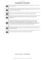
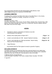
Installation Checklist
Did a structural engineer approve the mounting structure? See page 5 for Big Ass Fans-approved
mounting structures.
Are you familiar with the function and use of the safety cable? See pages 12 and 14 for information
on properly securing the safety cable.
:LOOWKHIDQEHLQVWDOOHGVRWKDWWKHDLUIRLOVDUHDWOHDVWIWPDERYHWKHÀRRU"
Will the fan be installed so that the airfoils have at least 2 ft (0.61 m) of clearance from
obstructions?
Will the fan be installed so that it is not subjected to high winds such as from a Heating,
Ventilating, and Air Conditioning (HVAC) system or near a large garage door? If the fan is
mounted at the same level or higher than a diffuser, the airfoil tips must be at a distance that is at least
1x the measure of the fan’s diameter. If the fan is mounted at the same height or below a diffuser, the
airfoil tips must be at a distance that is at least 2x the measure of the fan’s diameter.
Will the distance between multiple fans be at least 2.5x the fans’ diameter when measured from
the centers of the fans?
If you ordered multiple fans, did you keep the parts of each fan together?
Customer Service: 1-877-BIG-FANS
WWW.BIGASSFANS.COM
©2014 DELTA T CORP.
ALL RIGHTS RESERVED
BIG ASS FAN 2025
Installation Guide
i
Big Ass Fan 2025
Installation Guide:
Mar. 2014
Rev. A
This product was manufactured in a plant whose
0DQDJHPHQW6\VWHPLVFHUWL¿HGDVEHLQJLQ
conformity with ISO 9001:2008.
Conforms to ANSI/UL STD 507–Electric Fans
Conforms to CSA C22.2 No.113–Fans & Ventilators
Contact Information
Manufacturing
2425 Merchant Street
Lexington, KY 40511
%,*)$16
ZZZELJassfans.com
Customer Service
2348 Innovation Drive
Lexington, KY 40511
%,*)$16
ZZZELJassfans.com
Warranty Returns
800 Winchester Road
Lexington, KY 40505
%,*)$16
ZZZELJassfans.com
$OOWUDGHPDUNVXVHGKHUHLQDUHWKHSURSHUWLHVRIWKHLUUHVSHFWLYHRZQHUV1RSDUWRIWKLVGRFXPHQWPD\EHUHSURGXFHGRUWUDQVODWHGLQWRDGLIIHUHQWODQJXDJHZLWKRXWWKHSULRUZULWWHQFRQVHQWRI%LJAss Fan
&RPSDQ\7KHLQIRUPDWLRQFRQWDLQHGLQWKLVGRFXPHQWLVVXEMHFWWRFKDQJHZLWKRXWQRWLFH
WWW.BIGASSFANS.COM
©2014 DELTA T CORP.
ALL RIGHTS RESERVED
BIG ASS FAN 2025
ii
IMPORTANT SAFETY INSTRUCTIONS
READ AND SAVE THESE INSTRUCTIONS
TO REDUCE THE RISK OF FIRE, ELECTRIC SHOCK, OR INJURY TO PERSONS, OBSERVE THE FOLLOWING:
&$87,21,QVWDOODWLRQZRUNDQGHOHFWULFDOZLULQJPXVWEHGRQHE\TXDOL¿HGSHUVRQVLQDFFRUGDQFHZLWKDOODSSOLFDEOHFRGHVDQG
standards.
&$87,21:KHQFXWWLQJRUGULOOLQJLQWRZDOORUFHLOLQJGRQRWGDPDJHHOHFWULFDOZLULQJDQGRWKHUKLGGHQXWLOLWLHV
&$87,218VHWKLVXQLWRQO\LQWKHPDQQHULQWHQGHGE\WKHPDQXIDFWXUHU,I\RXKDYHTXHVWLRQVFRQWDFWWKHPDQXIDFWXUHU
:$51,1*%HIRUHVHUYLFLQJRUFOHDQLQJXQLWVZLWFKSRZHURIIDWVHUYLFHSDQHODQGORFNWKHVHUYLFHGLVFRQQHFWLQJPHDQVWRSUHYHQW
SRZHUIURPEHLQJVZLWFKHGRQDFFLGHQWDOO\:KHQWKHVHUYLFHGLVFRQQHFWLQJPHDQVFDQQRWEHORFNHGVHFXUHO\IDVWHQDSURPLQHQW
ZDUQLQJGHYLFHVXFKDVDWDJWRWKHVHUYLFHSDQHO
&$87,217KHLQVWDOODWLRQRID%LJAss )DQPXVWEHLQDFFRUGDQFHZLWKWKHUHTXLUHPHQWVVSHFL¿HGLQWKLVLQVWDOODWLRQPDQXDO
DQGZLWKDQ\DGGLWLRQDOUHTXLUHPHQWVVHWIRUWKE\WKH1DWLRQDO(OHFWULF&RGH1(&$16,1)3$DQGDOOORFDOFRGHV&RGH
FRPSOLDQFHLVXOWLPDWHO\<285UHVSRQVLELOLW\)DLOXUHWRFRPSO\ZLWKWKHVHFRGHVFRXOGUHVXOWLQSHUVRQDOLQMXU\RUSURSHUW\GDPDJH
&$87,21([HUFLVHFDXWLRQDQGFRPPRQVHQVHZKHQSRZHULQJWKHIDQ'RQRWFRQQHFWWKHIDQWRDGDPDJHGRUKD]DUGRXVSRZHU
VRXUFH'RQRWDWWHPSWWRUHVROYHHOHFWULFDOPDOIXQFWLRQVRUIDLOXUHVRQ\RXURZQ&RQWDFW%LJAss )DQVLI\RXKDYHDQ\TXHVWLRQV
UHJDUGLQJWKHHOHFWULFDOLQVWDOODWLRQRIWKLVIDQ
:$51,1*7RUHGXFHWKHULVNRI¿UHHOHFWULFVKRFNDQGLQMXU\WRSHUVRQV%LJAss )DQVPXVWEHLQVWDOOHGZLWK%LJAss )DQVXSSOLHG
FRQWUROOHUVWKDWDUHPDUNHGRQWKHLUFDUWRQVWRLQGLFDWHWKHVXLWDELOLW\ZLWKWKLVPRGHO2WKHUSDUWVFDQQRWEHVXEVWLWXWHG
&$87,21:KHQVHUYLFHRUUHSODFHPHQWRIDFRPSRQHQWLQWKHIDQUHTXLUHVWKHUHPRYDORUGLVFRQQHFWLRQRIDVDIHW\GHYLFHWKH
VDIHW\GHYLFHLVWREHUHLQVWDOOHGRUUHPRXQWHGDVSUHYLRXVO\LQVWDOOHG
:$51,1*5LVNRI¿UHHOHFWULFVKRFNRULQMXU\WRSHUVRQVGXULQJFOHDQLQJDQGXVHUPDLQWHQDQFH'LVFRQQHFWWKHIDQIURPWKHSRZHU
VXSSO\EHIRUHVHUYLFLQJ
&$87,21'RQRWEHQGWKHDLUIRLOVZKHQLQVWDOOLQJDGMXVWLQJRUFOHDQLQJWKHIDQ'RQRWLQVHUWIRUHLJQREMHFWVLQEHWZHHQURWDWLQJ
airfoils.
:$51,1*6WD\DOHUWZDWFKZKDW\RXDUHGRLQJDQGXVHFRPPRQVHQVHZKHQLQVWDOOLQJIDQV'RQRWLQVWDOOIDQVLIWLUHGRUXQGHUWKH
LQÀXHQFHRIGUXJVDOFRKRORUPHGLFDWLRQ$PRPHQWRILQDWWHQWLRQZKLOHLQVWDOOLQJIDQVPD\UHVXOWLQVHULRXVSHUVRQDOLQMXU\
&$87,217KHLQVWDOODWLRQRIWKLVIDQUHTXLUHVWKHXVHRIVRPHSRZHUWRROV)ROORZWKHVDIHW\SURFHGXUHVIRXQGLQWKHRZQHU¶V
PDQXDOIRUHDFKRIWKHVHWRROVDQGGRQRWXVHWKHPIRUSXUSRVHVRWKHUWKDQWKRVHLQWHQGHGE\WKHPDQXIDFWXUHU
&$87,217KH%LJAss )DQVSURGXFWZDUUDQW\ZLOOQRWFRYHUHTXLSPHQWGDPDJHRUIDLOXUHFDXVHGE\LPSURSHULQVWDOODWLRQ
:$51,1*7KLVDSSOLDQFHLVQRWLQWHQGHGIRUXVHE\SHUVRQVLQFOXGLQJFKLOGUHQZLWKUHGXFHGSK\VLFDOVHQVRU\RUPHQWDO
FDSDELOLWLHVRUODFNRIH[SHULHQFHDQGNQRZOHGJHXQOHVVWKH\KDYHEHHQJLYHQVXSHUYLVLRQRULQVWUXFWLRQFRQFHUQLQJXVHRI
WKHDSSOLDQFHE\DUHVSRQVLEOHSHUVRQ&KLOGUHQVKRXOGEHVXSHUYLVHGWRHQVXUHWKDWWKH\GRQRWSOD\ZLWKWKHDSSOLDQFH
/HDYHWKLVLQVWDOODWLRQJXLGHZLWKWKHRZQHURIWKHIDQDIWHULQVWDOODWLRQLVFRPSOHWH
WWW.BIGASSFANS.COM
©2014 DELTA T CORP.
ALL RIGHTS RESERVED
BIG ASS FAN 2025
Contents
Introduction
Important Safety Information
Thank You
About Big Ass Fans
About this Fan
ii
1
1
1
Pre-Installation
Parts Included
Tools Needed
Fan Diagram
Preparing the Work Site
2
3
4
5
Installing the Fan
1. Select Proper Angle Irons
2. Pre-drill Angle Irons
3. Secure Angle Irons (if span is longer than 8 ft)
4a. Fasten Single Angle Irons to Roof Structure Mounting Points
4b. Fasten Double Angle Irons to Roof Structure Mounting Points
5. Route Wiring and Safety Cable into Extension Tube
6. Attach Upper Mount and Upper Mounting Brace (to Extension Tube)
7. Attach Upper Mount (to Angle Irons)
8. Secure Safety Cable (to Main Fan Unit)
9. Attach Main Fan Unit (to Extension Tube)
10. Tighten Hardware
11. Secure Safety Cable (to Angle Irons)
12. Connect Power and Wall Controller Wiring
13. Install Cover Plate Assembly
14. Install Lower Cover Mounting Bracket
15. Install Lower Cover
16. Install Trim Ring
6
7
7
8
9
10
10
11
12
12
13
14
14
15
15
16
16
Installing Airfoils
1. Attach Airfoil Tips (to Airfoils)
2. Position Airfoils
3. Attach Airfoils (to Main Fan Unit)
17
17
18
Wiring the Fan
Electrical Safety Information
Power Requirements
Wiring Diagram
Wiring: Fire Signal Relay
19
19
19
20
Mounting the Wall
Controller
Dimensions
Mounting to a Wall
Mounting to a Junction Box
21
21
21
Operating the Fan
Operating the Wall Controller
Changing the Fan Direction
Heating Season
Cooling Season
22
22
23
23
Preventive Maintenance
Annual Preventive Maintenance
General Preventive Maintenance
24
24
Annual Maintenance
Checklist
Annual Maintenance Checklist
25
Troubleshooting
General Troubleshooting
Electrical Troubleshooting
Replacing Fuses
27
28
29
Warranty
Warranty Policy
Acknowledgment & Return Instructions
Warranty Claim Form Instructions
Warranty Claim Form
Responsibility Agreement
30
34
35
37
38
WWW.BIGASSFANS.COM
©2014 DELTA T CORP.
ALL RIGHTS RESERVED
Notes
BIG ASS FAN 2025
Introduction
1
Thank you and congratulations on your purchase of a Big Ass )DQDQHI¿FLHQWDQGFRVWHIIHFWLYHZD\WRVWD\FRROLQWKHVXPPHUDQG
ZDUPLQWKHZLQWHU7KHUHYROXWLRQDU\GHVLJQRIRXUIDQVFRPELQHVWKHEHVWRIERWKIRUPDQGIXQFWLRQWREULQJSRZHUSHUIRUPDQFHDQGD
VOHHNORRNWRDQ\VHWWLQJ0RUHLPSRUWDQWO\\RXKDYHSXUFKDVHGDSURGXFWWKDWLVEDFNHGE\H[WHQVLYHUHVHDUFKWKRURXJKWHVWLQJDQG
TXDOLW\PDQXIDFWXULQJ:H¶UHUHDG\WRDQVZHUDQ\TXHVWLRQVRUFRPPHQWVDW%,*)$16RUYLVLWRXU:HEVLWHDW
ZZZELJassfans.com.
Who we are and what we do
Big Ass )DQVKDVEHHQWKHSUHHPLQHQWPDQXIDFWXUHURIODUJHGLDPHWHUORZVSHHGIDQVVLQFH:LWKDZRUOGZLGHSUHVHQFHDQG
ORFDWHGLQEHDXWLIXO/H[LQJWRQ.<ZHUHVHDUFKGHVLJQDQGPDQXIDFWXUHWKHPRVWHIIHFWLYHDLUPRYHPHQWVROXWLRQVRQWKHPDUNHW
2XUQHYHUHQGLQJFRPPLWPHQWWRTXDOLW\DQGLQQRYDWLRQNHHSVXVDWWKHOHDGLQJHGJHRIDEXUJHRQLQJLQGXVWU\:LWKDQH\HWRKHOSLQJ
FXVWRPHUVVDWLVI\WKHLUQHHGVDQGDVWURQJVHQVHRIFRUSRUDWHUHVSRQVLELOLW\WRWKHFRPPXQLW\%LJAss )DQVKDVUHGH¿QHGWKHZD\
EXVLQHVVLVGRQH
About this fan
7HFKQLFDOVSHFL¿FDWLRQV
Fan diameter
Input power
Required
circuit size
Rated current
Max RPM
Airfoil length
7 ft (2.13 m)
110–125 VAC, 50/60 Hz, 1ĭ
10 A
5.1 A
198
35.5” (90.2 cm)
WWW.BIGASSFANS.COM
©2014 DELTA T CORP.
ALL RIGHTS RESERVED
BIG ASS FAN 2025
2
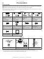
Pre-Installation
Parts included
&$87,21'RQRWUHPRYHWKHPDLQIDQXQLWIURPLWVSURWHFWLYHSDFNDJLQJRUSODFHLWRQDÀDWVXUIDFHSULRUWRKDQJLQJLW
CAUTION: If you ordered multiple fans, be sure to keep the components of each fan together.
,I\RXDUHPLVVLQJDQ\SLHFHUHTXLUHGIRULQVWDOODWLRQFRQWDFW%LJAss )DQV&XVWRPHU6HUYLFHNote: Drawings below are not to scale. All
boxes are labeled to identify the contents.
Hardware
Mounting Hardware
0[PP+H[+HDG
&DS6FUHZ
(8) M10 Flat Washer
01\ORFN1XW
Extension Tube Hardware
0[PP6RFNHW+HDG
&DS6FUHZ
(4) M10 Flat Washer
01\ORFN1XW
Safety Cable Hardware
´&OHYLV3LQ
&RWWHU3LQ
*ULSSOH®
Main Fan Unit Hardware
0[PP6RFNHW+HDG
&DS6FUHZ
(4) M8 Flat Washer
01\ORFN1XW
Airfoil Tip Hardware
0[PP%XWWRQ+HDG
6FUHZ
Airfoil Hardware
0[PP6RFNHW+HDG
&DS6FUHZ
PP%HOOHYLOOH:DVKHU
Cover Plate Assembly
Hardware
[´)ODW+HDG
6FUHZ
Lower Cover Mounting
Bracket Hardware
[´3DQ+HDG6FUHZ
Angle Iron Hardware
Lower Cover Hardware
[´3DQ+HDG6FUHZ ´6TXDUH:DVKHU
Mounting
Upper Mount & Upper Mounting Brace1
Main Fan Unit, Lower Cover, Lower
Cover Mounting Bracket, & Trim Ring
2-ft Extension Tube & Safety Cable2
1. 7KHXSSHUPRXQWLQJEUDFHVWUHQJWKHQVWKHXSSHUPRXQWLQJV\VWHPDQGPXVWEHLQVWDOOHGLQVLGHWKHWRSRIWKHH[WHQVLRQWXEH
2. 7ZRVDIHW\FOLSVDQGWZRFDUDELQHUVDUHSURYLGHGIRUVDIHW\FDEOHLQVWDOODWLRQLQORFDWLRQVZKHUHWKHWRSRIWKHPRXQWLQJVWUXFWXUHLV
LQDFFHVVLEOH&RQWDFW&XVWRPHU6HUYLFHLI\RXQHHGDVVLVWDQFHLQVWDOOLQJWKHVDIHW\FDEOH
WWW.BIGASSFANS.COM
©2014 DELTA T CORP.
ALL RIGHTS RESERVED
BIG ASS FAN 2025
3UH,QVWDOODWLRQFRQW
3
Parts included (cont.)
Note: Drawings below are not to scale.
Electrical
Airfoils
(6) Airfoil
Wall Controller
Cover Plate
Assembly1
Fire Relay2
(6) Airfoil Tip
20-ft Power
Supply Cable
3-ft Controller
Input Cable
(6) Airfoil Retainer
50-ft CAT5
Cable3
1. 7KHFRYHUSODWHDVVHPEO\LQFOXGHVDIDQVWDWXV/('DQGDVZLWFKXVHGWRFKDQJHWKHGLUHFWLRQRIIDQURWDWLRQ7KH/('ZLOOÀDVKDQHUURUFRGHLI
WKHUHLVDSUREOHPZLWKWKHIDQ6HHSDJHIRULQIRUPDWLRQRQWKHIDQVWDWXV/('6HHSDJHIRULQIRUPDWLRQRQFKDQJLQJWKHIDQGLUHFWLRQ
2. 7KH¿UHUHOD\LVSURYLGHGIRUIDQVWKDWZLOOEHLQVWDOOHGLQEXLOGLQJVWKDWKDYHD¿UHVSULQNOHUV\VWHP6HHSDJHIRU¿UHUHOD\ZLULQJGHWDLOV
3. 7KH&$7FDEOHFRQQHFWVWKHZDOOFRQWUROOHUWRWKHIDQ2QHHQGSOXJVLQWRWKHZDOOFRQWUROOHUDQGWKHRWKHUHQGSOXJVLQWRWKHFRQWUROOHULQSXWFDEOH
6HHSDJHV±IRUZLULQJGHWDLOV$ORQJHU&$7FDEOHFDQEHXVHGLIQHHGHGFXVWRPHUVXSSOLHG
Tools needed
Big Ass )DQVUHFRPPHQGVJDWKHULQJWKHIROORZLQJWRROVSULRUWREHJLQQLQJLQVWDOODWLRQ
Mechanical installation
Electrical installation
6WDQGDUGDQGPHWULFZUHQFKVHWV
3KLOOLSVDQGÀDWKHDGVFUHZGULYHUV
6WDQGDUGDQGPHWULFVRFNHWDQGUDWFKHWVHWV
WR$:*VWULSSHUV
7RUTXHZUHQFKFDSDEOHRIIWāOE1āP
Medium size channel locks
3KLOOLSVDQGÀDWKHDGVFUHZGULYHUV
Multimeter
0HWULF$OOHQZUHQFKVHW
Metric Allen head sockets
'ULOO
+DFNVDZ
/HYHO
Tape measure
WWW.BIGASSFANS.COM
©2014 DELTA T CORP.
ALL RIGHTS RESERVED
BIG ASS FAN 2025
3UH,QVWDOODWLRQFRQW
4
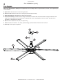
Fan diagram
5HIHUWRWKHGLDJUDPEHORZWRLGHQWLI\WKHIDQFRPSRQHQWVNote: The safety cable is not pictured below; however, it is an important part
of the installation.
A. Upper mount.6HFXUHVWKHIDQWRWKHPRXQWLQJVWUXFWXUH
B. Extension tube. ([WHQGVWKHIDQIURPWKHFHLOLQJDQGSURYLGHVDSDWKIRUZLULQJ
C. Upper mounting brace.6WUHQJWKHQVWKHXSSHUPRXQWLQJV\VWHP
D. Cover plate assembly.3URYLGHVDFFHVVWRZLULQJDQGLQFOXGHVDIDQVWDWXV/('DQGDVZLWFKXVHGWRFKDQJHWKHGLUHFWLRQRIIDQ
URWDWLRQ7KH/('ZLOOÀDVKDQHUURUFRGHLIWKHUHLVDSUREOHPZLWKWKHIDQ6HHSDJHIRU/('HUURUFRGHV6HHSDJHIRU
information on changing the fan direction.
E. Main fan unit. ,QFOXGHVWKHPRWRUKXEDQGSRZHUZLULQJ
F. Airfoil. 3URYLGHVDLUPRYHPHQW7KHXQLTXHSDWHQWHGGHVLJQSURYLGHVHI¿FLHQWDQGHIIHFWLYHDLUPRYHPHQW
G. Airfoil Tip.(QVXUHVTXLHWIDQRSHUDWLRQ
C
A
B
D
F
E
G
WWW.BIGASSFANS.COM
©2014 DELTA T CORP.
ALL RIGHTS RESERVED
BIG ASS FAN 2025
3UH,QVWDOODWLRQFRQW
5
Preparing the work site
The fan should only be installed according to the instructions described in this manual. Consult a structural engineer
for installation methods not covered in this manual.
:KHQVXUYH\LQJWKHZRUNVLWHNHHSWKHIROORZLQJPHFKDQLFDODQGHOHFWULFDOJXLGHOLQHVLQPLQG
Mechanical
• $VXLWDEOHPHDQVIRUOLIWLQJWKHZHLJKWRIWKHIDQVXFKDVDVFLVVRUOLIWDQGDWOHDVWWZRLQVWDOODWLRQSHUVRQQHOZLOOEHUHTXLUHG
• ,IKDQJLQJWKHIDQIURPDQJOHLURQVWKHPLQLPXPGLPHQVLRQVRIWKHDQJOHLURQPXVWEH¶¶î¶¶î¶¶
FPîFPîFPDQGLWFDQQRWEHORQJHUWKDQIWP,WPXVWEHVHFXUHGWRWKHVWUXFWXUH'RQRWPRXQWWKHIDQWRD
VLQJOHSXUOLQWUXVVRUEDUMRLVW&RQVXOWDVWUXFWXUDOHQJLQHHUIRULQVWDOODWLRQPHWKRGVQRWFRYHUHGLQWKLVPDQXDO
• 7RUHGXFHWKHULVNRILQMXU\WRSHUVRQVLQVWDOOWKHIDQVRWKDWWKHDLUIRLOVDUHDWOHDVWIWPDERYHWKHÀRRU
• ,IPRXQWLQJWKHIDQLQWKHYLFLQLW\RIDQLQIUDUHGUDGLDQWKHDWHULWLVUHFRPPHQGHGWKDWWKHIDQEHPRXQWHGRXWVLGHRIWKHFOHDUDQFHV
UHFRPPHQGHGE\WKHPDQXIDFWXUHURIWKHKHDWHUDQGDWDKHLJKWHTXDOWRRUDERYHWKHVKLHOGLQJRQWKHKHDWLQJHOHPHQWZLWKWKH
FRQWUROOHURQWKHRSSRVLWHVLGHRIWKHKHDWHU,IPRXQWLQJWKHIDQEHORZWKHKHDWHUVKLHOGLQJDOOIDQHOHPHQWVPXVWEHRXWVLGHRIWKH
FOHDUDQFHVUHFRPPHQGHGE\WKHKHDWHUPDQXIDFWXUHU7KHLQVWDOODWLRQPDQXDOIRUWKHVSHFL¿FPRGHORIKHDWHUZLOOW\SLFDOO\SURYLGH
WKHPLQLPXPFOHDUDQFHWRFRPEXVWLEOHV0&&
• $GKHUHWRWKHVDIHW\UHTXLUHPHQWVLQWKHWDEOHEHORZZKHQVHOHFWLQJZKHUHWRPRXQWWKHIDQ
Safety requirement
Minimum distances
Clearance
IWIURPDOOIDQSDUWVDQGIWEHORZVSULQNOHUV7KHIDQLQVWDOODWLRQDUHDPXVWDOVREHIUHHRI
REVWUXFWLRQVVXFKDVOLJKWVFDEOHVRURWKHUEXLOGLQJVWUXFWXUH
Blade height
IWDERYHWKHIORRU
HVAC equipment
[IDQGLDPHWHULIDERYHGLIIXVHU[IDQGLDPHWHULIEHORZGLIIXVHU5HIHUWRWKHLOOXVWUDWLRQEHORZ
Fan spacing
[IDQGLDPHWHUFHQWHUWRFHQWHU
5DGLDQW,5KHDWHUV
6HHWKHPDQXIDFWXUHU¶VUHTXLUHPHQWVIRUWKHPLQLPXPFOHDUDQFHWRFRPEXVWLEOHV
,IWKHIDQLVPRXQWHGDWWKHVDPHOHYHO
or higher than a diffuser, the airfoil tips
PXVWEHDWDGLVWDQFHWKDWLVDWOHDVW[
the measure of the fan’s diameter.
HVAC
Diffuser
[IDQ¶VGLDPHWHU
(7 ft)
(2.1 m)
IWGLDPHWHU
,IWKHIDQLVPRXQWHGEHORZDGLIIXVHU
WKHDLUIRLOWLSVPXVWEHDWDGLVWDQFH
WKDWLVDWOHDVW[WKHPHDVXUHRIWKH
fan’s diameter.
HVAC
Diffuser
[IDQ¶VGLDPHWHU
(14 ft)
(4.3 m)
IWGLDPHWHU
Electrical
• (QVXUHSRZHUZLULQJLVURXWHGWRDMXQFWLRQER[DWWKHIDQORFDWLRQSULRUWRLQVWDOODWLRQ
• 7RUHGXFHWKHULVNRIHOHFWULFVKRFNZLULQJVKRXOGEHSHUIRUPHGE\DTXDOL¿HGHOHFWULFLDQ,QFRUUHFWDVVHPEO\FDQFDXVHHOHFWULF
VKRFNRUGDPDJHWKHPRWRUDQGWKHFRQWUROOHU
• ,QVWDOODWLRQRID%LJAss )DQPXVWEHLQDFFRUGDQFHZLWKWKH1DWLRQDO(OHFWULFDO&RGH1(&$16,1)3$DQGORFDOFRGHV
WWW.BIGASSFANS.COM
©2014 DELTA T CORP.
ALL RIGHTS RESERVED
BIG ASS FAN 2025
6
Installing the Fan
WARNING: The fan weighs 70 lbs (31.8 kg). The fan should not be installed unless the structure on which the fan is to
be mounted is of sound construction, undamaged, and capable of supporting the loads of the fan and its method of
attachment. A structural engineer should verify that the mounting structure is adequate prior to fan installation. Verifying
the stability of the mounting structure is the sole responsibility of the customer and/or end user, and Big Ass Fans hereby
expressly disclaims any liability arising therefrom, or arising from the use of any materials or hardware other than those
supplied by Big Ass )DQVRURWKHUZLVHVSHFL¿HGLQWKHVHLQVWDOODWLRQLQVWUXFWLRQV
CAUTION: Do not install the fan from a single purlin or truss or junction box.
CAUTION: Unsupported angle iron spans should not exceed 12 ft (3.7 m).
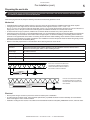
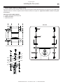
1. Select proper angle irons
Follow the table below when selecting angle irons for fan installation. Note: Angle irons and angle iron hardware are not included with
the fan.
Angle iron span
(between mounting points)
Minimum angle iron dimensions
(W x H x T)
Number of angle
irons needed
6 ft (1.8 m) or less
2.5” (6.4 cm) x 2.5” (6.4 cm) x 0.25” (0.6 cm)
2
over 6 ft (1.8 m) to 8 ft (2.4 m)
3” (7.6 cm) x 3” (7.6 cm) x 0.25” (0.6 cm)
2
over 8 ft (2.4 m) to 12 ft (3.7 m)
3” (7.6 cm) x 3” (7.6 cm) x 0.25” (0.6 cm)
4*
Angle Iron Side View
(see table for dimensions)
Height
Thickness
*Two pairs of angle irons. Pairs should be placed back to back and fastened in center (see step 3).
Width
m)
’ (1.8
ss
or le
6
) - 8’
1.8m
(
’
6
over
)
(2.4m
)
3.7m
12’ (
)
.4m
8’ (2
over
WWW.BIGASSFANS.COM
©2014 DELTA T CORP.
ALL RIGHTS RESERVED
BIG ASS FAN 2025
Installing the Fan (cont.)
7
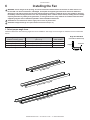
2. Pre-drill angle irons
Drill two Ø 9/16” (1.4 cm) holes exactly 5-1/2” (14 cm) apart in the centers of two angle irons.
Measure the distance between the mounting points of the roof structure that the angle irons will span. Measure the same distance on
the angle irons, and drill Ø 9/16” (1.4 cm) holes through each end of the angle irons. Drill holes in two angle irons if span is 8 ft (2.4 m)
or less. Drill holes in four angle irons if span is greater than 8 ft (2.4 m).
A
Ø 9/16" (1.4 cm)
Ø 9/16" (1.4 cm)
1/2 A
5 1/2” (14 cm)
distance between roof
structure mounting points
3. Secure angle irons (if span is longer than 8 ft)
If the angle iron span is 8 ft (2.4 m) or less, proceed to
step 4a on the following page.
c
b
If the angle iron span is longer than 8 ft (2.4 m), it is necessary to
use double angle irons.
Locate the center of the angle iron length. Drill Ø 9/16” (1.4 cm) hole
through the center of the vertical wall of the angle iron. Drill a total of
four angle irons.
Place two drilled angle irons back to back. Fasten the angle irons
together with customer-supplied Grade 8 hardware.
b
Align the angle irons to each other and tighten the bolts to 25 ft·lb
(33.9 N·m) using a torque wrench with a 3/4” or 19 mm socket.
a
Repeat step for remaining two angle irons.
Side View
Proceed to step 4b.
Angle Iron Hardware (Customer-Supplied):
a. (2) 1/2-13 or M12 Bolt
b. (4) 1/2” or M12 Washer
c. (2) 1/2” or M12 Nut
WWW.BIGASSFANS.COM
©2014 DELTA T CORP.
ALL RIGHTS RESERVED
BIG ASS FAN 2025
Installing the Fan (cont.)
8
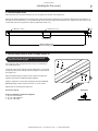
4a. Fasten single angle irons to roof structure mounting points
If installation requires double angle irons, i.e., span is greater than 8 ft (2.4 m), proceed to step 4b.
CAUTION: The angle irons must be fastened to the roof structure at each end.
Fasten the angle irons to the roof structure mounting points at each end with customer-supplied Grade 8 hardware as shown. Tighten
the hardware so that it is snug, but do not torque until the fan has been mounted to the angle irons. Note: Big Ass Fans
recommends orienting the angle irons so that the horizontal legs are facing each other. Refer to the illustration below.
Proceed to step 5.
Angle Iron Hardware (Customer-Supplied):
a. (4) 1/2-13 or M12 Bolt
b. (8) 1/2” or M12 Washer
c. (4) 1/2” or M12 Nut
Angle Iron Hardware (BAF-Supplied):
d. (8) 3” Square Washer (see diagram)
Square Washer
3”
(7.6 cm)
a
Ø 9/16”
(1.4 cm)
b
3”
(7.6 cm)
Thickness:
1/4” (6 mm)
d
b
c
WWW.BIGASSFANS.COM
©2014 DELTA T CORP.
ALL RIGHTS RESERVED
BIG ASS FAN 2025
Installing the Fan (cont.)
9
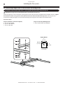
4b. Fasten double angle irons to roof structure mounting points
CAUTION: The angle irons must be fastened to the roof structure at each end.
Fasten the angle irons to the roof structure mounting points at each end with customer-supplied Grade 8 hardware as shown. Tighten
the hardware so that it is snug, but do not torque until the fan has been mounted to the angle irons.
Proceed to step 5.
Angle Iron Hardware (Customer-Supplied):
a. (8) 1/2-13 or M12 Bolt
b. (16) 1/2” or M12 Washer
c. (8) 1/2” or M12 Nut
Angle Iron Hardware (BAF-Supplied):
d. (8) 3” Square Washer (see diagram)
Square Washer
3”
(7.6 cm)
Ø 9/16”
(1.4 cm)
a
3”
(7.6 cm)
b
Thickness:
1/4” (6 mm)
d
b
c
WWW.BIGASSFANS.COM
©2014 DELTA T CORP.
ALL RIGHTS RESERVED
BIG ASS FAN 2025
Installing the Fan (cont.)
10
5. Route wiring and safety cable into extension tube
Controller Input
Cable
Note: To facilitate installation, Big Ass Fans recommends that the extension
tube is horizontal with the rectangular access hole facing up during this step.
Power Supply
Cable
To route the wiring and safety cable into the extension tube:
1. Route the end of the controller input cable with the wiring harness on it (the
end without the three loose wires) down into the top of the extension tube
and out the rectangular access hole as shown.
2. Route the end of the power supply cable with the wiring harness on it down
into the top of the extension tube and out the rectangular access hole as
shown.
Access Hole
3. Route the end of the safety cable with the lug on it down into the top of the
extension tube and out the bottom of the tube as shown.
Safety Cable
6. Attach upper mount and upper mounting brace (to extension tube)
Note: To facilitate installation, Big Ass Fans recommends that the extension tube is horizontal with
the rectangular access hole facing up during this step. Wiring and the and safety cable are not
shown in the illustrations.
Upper
Mounting
Brace
Insert the upper mounting brace into the top of the extension tube and align the four (4) mounting
holes in the brace with the four (4) mounting holes at the top of the tube as shown on the right.
Position the power supply cable, controller input cable, and safety cable in any of the four (4)
spaces between the upper mounting brace and the extension tube as shown below. Note: The
cables can go in any of the four spaces. They do not all need to be in the same space.
Attach the upper mounting brace (inside the extension tube) and the upper mount to the extension
tube using the Extension Tube Hardware as shown below. Tighten the hardware so that it is
snug, but do not torque.
Extension Tube Hardware (BAF-Supplied):
a. (2) M10 x 90 mm Socket Head Cap Screw
b. (4) M10 Flat Washer
c. (2) M10 Nylock Nut
b
Spaces for cables
(use any of the four)
Upper Mounting Brace
a
Extension tube with upper
mounting brace inside
(view from above)
WWW.BIGASSFANS.COM
b
©2014 DELTA T CORP.
ALL RIGHTS RESERVED
c
BIG ASS FAN 2025
Installing the Fan (cont.)
11
7. Attach upper mount (to angle irons)
Secure the upper mount (with extension tube and upper mounting brace already attached) directly to the angle irons using the Mounting
Hardware as shown. Consult the diagrams below for distances between the angle irons. Tighten the hardware so that it is snug, but
do not torque.
Mounting Hardware (BAF-Supplied):
a. (4) M10 x 40 mm Hex Head Cap Screw
b. (8) M10 Flat Washer
c. (4) M10 Nylock Nut
Side View
5 1/2” (14.6cm)
a
5 1/2” (14.6cm)
b
Note: Dashed lines represent angle irons.
b
c
WWW.BIGASSFANS.COM
©2014 DELTA T CORP.
ALL RIGHTS RESERVED
BIG ASS FAN 2025
Installing the Fan (cont.)
12
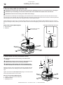
8. Secure safety cable (to main fan unit)
&$87,21'RQRWUHPRYHWKHPDLQIDQXQLWIURPLWVSURWHFWLYHSDFNDJLQJRUSODFHLWRQDÀDWVXUIDFHSULRUWRKDQJLQJLW
&$87,217RSUHYHQWGDPDJHDYRLGFRQWDFWZLWKWKHVWDWRUZLUHVORFDWHGRQWKHERWWRPRIWKHPDLQIDQXQLW
CAUTION: The main fan unit is heavy. Use caution when raising it.
Raise the main fan unit directly from its packaging to the extension tube. Route the three (3) sets of wires from the main fan unit up
into the bottom of the extension tube and out the rectangular access hole near the bottom of the tube. Ensure the wires are positioned
inside the grooves on the motor shaft. Note: Wiring not shown in the illustrations below.
While supporting the main fan unit, secure the safety cable to the motor shaft using the Safety Cable Hardware as shown. Insert the
clevis pin through the safety cable lug and motor shaft, and then insert the straight leg of the cotter pin into the small hole on the clevis
pin.
Cotter pin inserted into clevis pin
Safety Cable Hardware (BAF-Supplied):
a. 5/16” Clevis Pin
b. Cotter Pin
Route wires from main
fan unit out here
Safety
Cable
Safety
Cable
a
b
b
a
9. Attach main fan unit (to extension tube)
CAUTION: The main fan unit is heavy. Use caution when
raising it.
CAUTION: Be careful not to pinch the fan wiring between the
extension tube and main fan unit during installation.
b
b
a
CAUTION: Do not discard the main fan unit packaging and
foam. It should be used if the fan is ever moved or relocated.
Attach the main fan unit to the extension tube using the Main Fan Unit
Hardware as shown. Note: Wiring not shown in the illustration on the
right.
Tighten the hardware to 25 ft·lb (33.9 N·m) using a 6 mm Allen wrench
and a torque wrench with a 13 mm socket.
Main Fan Unit Hardware (BAF-Supplied):
a. (2) M8 x 75 mm Socket Head Cap Screw
b. (4) M8 Flat Washer
c. (2) M8 Nylock Nut
WWW.BIGASSFANS.COM
©2014 DELTA T CORP.
ALL RIGHTS RESERVED
c
BIG ASS FAN 2025
Installing the Fan (cont.)
13
10. Tighten hardware
$IWHUDWWDFKLQJWKHPDLQIDQXQLWWRWKHH[WHQVLRQWXEHWLJKWHQWKHIROORZLQJKDUGZDUHWRWKHVSHFL¿HGWRUTXH
Tighten the Mounting Hardware to 25 ft·lb (33.9 N·m) using a 17 mm wrench and a torque wrench with a 17 mm socket.
Mounting Hardware
Allow the extension tube to hang freely and balance itself, and then tighten the Extension Tube Hardware to 25 ft·lb (33.9 N·m) using
an 8 mm Allen wrench and a torque wrench with a 17 mm socket.
Extension Tube Hardware
Tighten all hardware securing the angle irons to the roof structure (Angle Iron Hardware) to 40 ft·lb (54.2 N·m) using a 3/4” or 19 mm
wrench and a torque wrench with a 3/4” or 19 mm socket.
Angle Iron Hardware (single angle irons)
WWW.BIGASSFANS.COM
Angle Iron Hardware (double angle irons)
©2014 DELTA T CORP.
ALL RIGHTS RESERVED
BIG ASS FAN 2025
Installing the Fan (cont.)
14
11. Secure safety cable (to angle irons)
WARNING: The safety cable is a crucial part of the fan and must be installed correctly. If you have any questions, call
Customer Service.
To secure the safety cable to the angle irons:
1. Route the free end of the safety cable into one of the two (2) holes in the Gripple®, and then pull the cable through the Gripple until
the Gripple rests at the top of the extension tube.
2. Wrap the safety cable tightly around the angle irons as shown, leaving as little slack as possible.
3. Route the loose end of the safety cable through the remaining hole in the Gripple and pull to tighten.
12. Connect power and wall controller wiring
Plug the male wiring harnesses on the fan wiring into the female
wiring harnesses on the power supply cable and the controller input
cable as shown. Carefully tuck the wiring into the extension tube.
Power Supply
Cable
Controller Input
Cable
Power Wiring
from Fan
(3 wires)
Wall Controller Wiring from Fan
(8 wires)
Cover Plate Assembly Wiring from Fan
(4 wires, to be connected later)
WWW.BIGASSFANS.COM
©2014 DELTA T CORP.
ALL RIGHTS RESERVED
BIG ASS FAN 2025
Installing the Fan (cont.)
15
13. Install cover plate assembly
Plug the remaining male wiring harness from the fan into the female
wiring harness on the cover plate assembly as shown.
Ensure all wiring is tucked inside the extension tube, and then attach
the cover plate assembly to the extension tube using the Cover Plate
Assembly Hardware as shown.
Cover Plate
Assembly
Cover Plate Assembly Hardware (BAF-Supplied):
(2) 8-32 x 1/2" Flat Head Screw
14. Install lower cover mounting bracket
Remove the protective plastic cover from the bottom of the main fan unit before installing the mounting bracket.
Ensure that the three (3) stator wires on the bottom of the main fan unit are tucked in securely before installing the
mounting bracket. Be careful not to damage the stator wires while installing the mounting bracket and lower cover.
WARNING: Disconnect power to the fan before installing the lower cover mounting bracket and lower cover.
Attach the lower cover mounting bracket to the bracket on the bottom of the main fan unit using the Lower Cover Mounting Bracket
Hardware as shown. Loosely attach all three (3) screws, and then tighten them.
Lower Cover Mounting Bracket Hardware (BAF-Supplied):
(3) 8-32 x 3/8" Pan Head Screw
Lower Cover
Mounting Bracket
WWW.BIGASSFANS.COM
©2014 DELTA T CORP.
ALL RIGHTS RESERVED
BIG ASS FAN 2025
Installing the Fan (cont.)
16
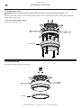
15. Install lower cover
WARNING: Disconnect power to the fan before installing the lower cover mounting bracket and lower cover.
Attach the lower cover to the lower cover mounting bracket using the Lower Cover Hardware as shown. Loosely attach all eight (8)
screws, and then tighten them.
Lower Cover Hardware (BAF-Supplied)
(8) 6-32 x 3/8" Pan Head Screw
Lower Cover
16. Install trim ring
Snap the trim ring onto the lower cover as shown.
Trim Ring
WWW.BIGASSFANS.COM
©2014 DELTA T CORP.
ALL RIGHTS RESERVED
BIG ASS FAN 2025
Installing Airfoils
17
Big Ass Fans recommends wiring the fan (page 19) before installing the airfoils.
WARNING: Disconnect power to the fan before installing the airfoils.
1. Attach airfoil tips (to airfoils)
Attach the airfoil tips to the airfoils using the Airfoil Tip Hardware as shown. Securely tighten the screws using a 3 mm Allen wrench.
Attach airfoil tips to all six (6) airfoils before attaching the airfoils to the fan.
Airfoil Tip Hardware (BAF-Supplied):
(6) M5 x 12 mm Button Head Screw
2. Position airfoils
Slide the airfoils onto the tabs as shown.
WWW.BIGASSFANS.COM
©2014 DELTA T CORP.
ALL RIGHTS RESERVED
BIG ASS FAN 2025
18
Installing Airfoils (cont.)
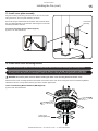
3. Attach airfoils (to main fan unit)
WARNING: Disconnect power to the fan before installing airfoils.
Attach the six (6) airfoil retainers using the Airfoil Hardware. Moving clockwise around the fan hub, position the airfoil retainers as
shown. Hole A of the retainer should be positioned over top of Hole B. Do not tighten the bolts until all airfoil retainers have been
DWWDFKHG
Tighten the bolts along the outside perimeter to 29 ft·lb (39.3 N·m) using a torque wrench with a 6 mm Allen head socket. After the
outer perimeter bolts are torqued, tighten the bolts along the inner perimeter to 29 ft·lb (39.3 N·m).
Airfoil Hardware (BAF-Supplied):
a. (12) M8 x 18 mm Socket Head Cap Screw
b. (12) 8 mm Belleville Washer
Belleville Washer
Airfoil Retainer
Hole A
Hole B
a
b
WWW.BIGASSFANS.COM
©2014 DELTA T CORP.
ALL RIGHTS RESERVED
BIG ASS FAN 2025
Wiring the Fan
19
:$51,1*7RUHGXFHWKHULVNRIHOHFWULFVKRFNZLULQJVKRXOGEHSHUIRUPHGE\DTXDOL¿HGHOHFWULFLDQ,QFRUUHFWDVVHPEO\
FDQFDXVHHOHFWULFVKRFNRUGDPDJHWKHPRWRUDQGWKHFRQWUROOHU+D]DUGRIHOHFWULFDOVKRFN
WARNING: The installation of a Big Ass)DQPXVWEHLQDFFRUGDQFHZLWKWKHUHTXLUHPHQWVVSHFL¿HGLQWKLVLQVWDOODWLRQ
manual and with any additional requirements set forth by the National Electric Code (NEC), ANSI/NFPA 70-2011, and all
ORFDOFRGHV&RGHFRPSOLDQFHLVXOWLPDWHO\<285UHVSRQVLELOLW\
CAUTION: The Big Ass Fans product warranty will not cover damage or failure caused by improper installation.
WARNING: Exercise caution and common sense when powering the fan. Do not connect the fan to a damaged or
KD]DUGRXVSRZHUVRXUFH'RQRWDWWHPSWWRUHVROYHHOHFWULFDOPDOIXQFWLRQVRUIDLOXUHVRQ\RXURZQ&RQWDFW%LJAss Fans
if you have any questions regarding the electrical installation of this fan.
Power requirements
Fan diameter
Input power
5HTXLUHGFLUFXLWVL]H
Rated current
7 ft (2.13 m)
110–125 VAC, 50/60 Hz, 1ĭ
10 A
5.1 A
Wiring diagram
Yellow
Run Enable
Closed: Enable,
Open: Disable
Blue
Green
Status LED (-)
Red
+10 VDC Supply
Black
DC Common
Power Supply
Cable
WHITE
WHITE
Status LED (+)
BLUE
L2 / AC NEUTRAL
Not Used
Orange
GREEN OR BARE COPPER
Brown
PE / GROUND
+0-10 VDC
Speed Ref.
BLACK
White
L1 / AC LINE
Power Supply
±9$&ĭ
10 A 50/60 Hz
Controller Input Cable
YELLOW
Controller
Input Cable
CAT5 Cable
BROWN
(not used)
GREEN
BLACK
To wall
controller
Wall Controller
See page 21 for
mounting instructions.
WWW.BIGASSFANS.COM
©2014 DELTA T CORP.
ALL RIGHTS RESERVED
BIG ASS FAN 2025
20
Wiring the Fan (cont.)
Wiring: Fire signal relay
:$51,1*7RUHGXFHWKHULVNRIHOHFWULFVKRFNZLULQJVKRXOGEHSHUIRUPHGE\DTXDOL¿HGHOHFWULFLDQ,QFRUUHFWDVVHPEO\
FDQFDXVHHOHFWULFVKRFNRUGDPDJHWKHPRWRUDQGWKHFRQWUROOHU+D]DUGRIHOHFWULFDOVKRFN
&$87,21,QVWDOODWLRQZRUNDQGHOHFWULFDOZLULQJPXVWEHGRQHE\TXDOL¿HGSHUVRQVLQDFFRUGDQFHZLWKDOODSSOLFDEOH
codes and standards.
$77(17,21,ILQVWDOOLQJWKH¿UHUHOD\WKHIDQPXVWEHLQVWDOOHGSHUWKHIROORZLQJ1DWLRQDO)LUH3URWHFWLRQ$VVRFLDWLRQ1)3$
guidelines:
• The fan must be centered approximately between four adjacent sprinklers.
7KHYHUWLFDOGLVWDQFHIURPWKHIDQWRWKHVSULQNOHUGHÀHFWRUPXVWEHDWOHDVWIWFP
7KHIDQPXVWEHLQWHUORFNHGWRVKXWGRZQLPPHGLDWHO\XSRQUHFHLYLQJDZDWHUÀRZVLJQDOIURPWKHDODUPV\VWHP
7KH¿UHUHOD\LVSURYLGHGIRUIDQVWKDWZLOOEHLQVWDOOHGLQEXLOGLQJVWKDWKDYHD¿UHVSULQNOHUV\VWHP7KH¿UHUHOD\LQWHJUDWHVWKHIDQZLWK
WKHVSULQNOHUV\VWHPDQGVKXWVGRZQWKHIDQXSRQUHFHLYLQJDQDODUPVLJQDOIURPWKHV\VWHP
Controller Input Cable
WHITE
+0-10 VDC Speed Ref.
Brown
Not Used
Orange
Status LED (+)
Yellow
Run Enable
Closed: Enable, Open: Disable
RED
DC Common
YELLOW
Power Supply
±9$&ĭ
10 A 50/60 Hz
ORANGE
BLUE
YELLOW
BLUE
WHITE
Black
WHITE
WHITE
GREEN OR BARE COPPER
+10 VDC Supply
CAT5 Cable
Power Supply
Cable
WHITE
PE / GROUND
Status LED (-)
Red
L2 / AC NEUTRAL
Green
From main
FACP or
NAC box, if
applicable
RED
BLACK
Blue
RED
L1 / AC LINE
White
BROWN
(not used)
Controller
Input Cable
GREEN
BLACK
To wall
controller
Wall Controller
See page 21 for
mounting instructions.
WWW.BIGASSFANS.COM
©2014 DELTA T CORP.
ALL RIGHTS RESERVED
BIG ASS FAN 2025
Mounting the Wall Controller
21
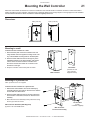
0RXQWWKHZDOOFRQWUROOHUVRWKDWWKHIDQLWFRQWUROVLVYLVLEOHIURPWKHFRQWUROOHUORFDWLRQ,QVWDOOWKHFRQWUROOHURQDÀDWVXUIDFHWKDWLV
UHDGLO\DFFHVVLEOHIUHHIURPYLEUDWLRQDQGZKHUHWKHUHLVDGHTXDWHGLVWDQFHIURPIRUHLJQREMHFWVRUPRYLQJHTXLSPHQW The controller
FDQEHVXUIDFHPRXQWHGWRDZDOORUPRXQWHGWRDFXVWRPHUVXSSOLHGMXQFWLRQER[
Dimensions
´FP
´FP
´FP
Mounting to a wall
To mount the wall controller to a wall:
1. Attach the back plate of the wall controller to the wall
using suitable customer-supplied mounting screws. Use
DQ\RIWKHDYDLODEOHPRXQWLQJKROHVRQWKHEDFNSODWH
2. Route the CAT5 cable from the fan through any of the
DYDLODEOHNQRFNRXWVRQWKHZDOOFRQWUROOHUDQGFRQQHFW
it to the CAT5 connector inside the controller. Note:
Knockouts and the CAT5 cable are not shown in the
illustration on the right.
3. Snap the controller onto the back plate as shown.
Wall Controller
Back Plate
(mounted to wall
with customersupplied screws)
Mounting to a junction box
Note: A junction box is not supplied.
To mount the wall controller to a junction box:
1. 5HPRYHWKHZDOOFRQWUROOHU¶VIURQWFRYHUDVVHPEO\E\
XQVFUHZLQJWKHWZRVFUHZVRQWKHIURQWFRYHU6HWWKH
screws aside in a safe location.
CAT5
Cable
2. 5RXWHWKH&$7FDEOHIURPWKHIDQLQWRWKHMXQFWLRQER[
DQGFRQQHFWLWWRWKH&$7FRQQHFWRURQWKHIURQWFRYHU
assembly.
3. 0RXQWWKHIURQWFRYHUDVVHPEO\WRWKHMXQFWLRQER[XVLQJ
the two (2) screws as shown.
:DOO&RQWUROOHU+DUGZDUH%$)6XSSOLHG
[´2YDO+HDG6FUHZ
WWW.BIGASSFANS.COM
Junction Box
(in wall,
customer-supplied)
Wall Controller
Front Cover Assembly
©2014 DELTA T CORP.
ALL RIGHTS RESERVED
BIG ASS FAN 2025
22
Operating the Fan
Operating the wall controller
To start the fan, press the control knob on the wall controller. Note: When power
LVDSSOLHGWKH/('LQGLFDWRUDWWKHWRSRIWKHFRQWUROOHULVOLW7KH/('ZLOOÀDVKDQ
error code if there is a problem with the fan. See page 28 for LED error codes.
/(',QGLFDWRU
To stop the fan, press the control knob.
To increase fan speed,WXUQWKHFRQWURONQREFORFNZLVHWRZDUG+,*+
To decrease fan speed, turn the control knob counterclockwise toward LOW.
Note: The fan may take 30–60 seconds to start rotating after it is turned on. It is normal to see an initial slight jerking forward and
backward upon startup as the fan positions itself relative to the motor stator.
Changing the fan direction
Big Ass Fans recommends operating the fan in the forward (FWD) direction. The fan should be rotating
counterclockwise when viewed from below.
To reverse the direction of the fan,UHPRYHSRZHUIURPWKHIDQ6HOHFWWKHGLUHFWLRQRIWKHIDQXVLQJWKHIDQGLUHFWLRQVHOHFWRUVZLWFK
ORFDWHGRQWKHIDQ¶VFRYHUSODWHDVVHPEO\5HDSSO\SRZHUWRWKHIDQ)RUIDQVWDWXV/('GH¿QLWLRQVVHHSDJH
Fan Direction
Selector Switch
&RYHU3ODWH
Assembly
Fan Status LED
WWW.BIGASSFANS.COM
©2014 DELTA T CORP.
ALL RIGHTS RESERVED
BIG ASS FAN 2025
Operating the Fan (cont.)
0RYLQJDWDORZVSHHGPHDQVOHVVHQHUJ\XVHGIRURSHUDWLRQWUDQVODWLQJLQWRPRUHHQHUJ\VDYLQJV\HDUURXQG)ROORZWKHSURFHGXUHV
EHORZWRHQVXUHWKHPRVWHI¿FLHQWRSHUDWLRQRI\RXU%LJAss Fan.
To ensure proper fan rotation:
1. Turn on the fan.
2. 9HULI\WKDWWKHIDQLVURWDWLQJLQWKHFRXQWHUFORFNZLVHGLUHFWLRQZKHQYLHZHGIURPEHORZ
3. ,IWKHIDQLVQRWURWDWLQJFRXQWHUFORFNZLVHUHYHUVHWKHIDQGLUHFWLRQ6HHWKHSUHYLRXVSDJHIRULQVWUXFWLRQVRQFKDQJLQJWKHGLUHFWLRQ
of rotation.
+HDWLQJVHDVRQ
,QVSDFHVZLWKKLJKHUFHLOLQJV%LJAss )DQIDQVUHWXUQKHDWIURPWKHFHLOLQJWRÀRRUOHYHOPRUHHI¿FLHQWO\WKDQVPDOOHUFHLOLQJ
IDQV)RUPD[LPXPHQHUJ\VDYLQJVWKHIDQVKRXOGEHRSHUDWHGFRQWLQXRXVO\GXULQJWKHKHDWLQJVHDVRQDQGVKRXOGQRWEHRSHUDWHGLQ
UHYHUVHFORFNZLVH%LJAss )DQVDUHGHVLJQHGWRRSHUDWHHI¿FLHQWO\DWYHU\ORZVSHHGVVRWXUQLQJWKHIDQYHU\VORZO\LQWKHIRUZDUG
GLUHFWLRQFRXQWHUFORFNZLVHZLOOSURYLGHHQRXJKDLUPRYHPHQWWRFLUFXODWHWKHKRWDLUDWWKHFHLOLQJGRZQWRWKHÀRRUZLWKRXWFDXVLQJD
draft.
6WDQGGLUHFWO\EHORZWKHWLSVRIWKHDLUIRLOVZLWKKDQGRXWVWUHWFKHG,I\RXIHHODGUDIWVOLJKWO\GHFUHDVHWKHIDQVSHHG5HSHDWXQWLOWKH
draft is no longer noticeable.
Cooling season
The cooling effect created by the breeze from Big Ass Fan 2025 fans keeps occupants comfortable with the thermostat at a higher
VHWWLQJ'XULQJWKHFRROLQJVHDVRQHYHU\GHJUHHKLJKHUWKDWWKHWKHUPRVWDWLVUHVHWUHGXFHVWKHHQHUJ\FRQVXPHGE\WKHDLUFRQGLWLRQHU
by 1.5–2%. To minimize energy usage during the cooling season, operate the fan only when building occupants are present.
,QFUHDVHWKHVSHHGRIWKHIDQXQWLOGHVLUHGDLUVSHHGRUPD[LPXPIDQVSHHGLVUHDFKHG,QDLUFRQGLWLRQHGIDFLOLWLHVLQFUHDVHWKH
WKHUPRVWDWVHWWLQJE\WR)WRUHGXFHHQHUJ\FRQVXPSWLRQDQGVDYHHQHUJ\
WWW.BIGASSFANS.COM
©2014 DELTA T CORP.
ALL RIGHTS RESERVED
BIG ASS FAN 2025
24
Preventive Maintenance
WARNING: Before servicing or cleaning unit, switch power off at the service panel and lock the service disconnecting
means to prevent power from being switched on accidentally. When the service disconnecting means cannot be locked,
securely fasten a prominent warning device (such as a tag) to the service panel.
WARNING: When service or replacement of a component in the fan requires the removal or disconnection of a safety
device, the safety device is to be reinstalled or remounted as previously installed.
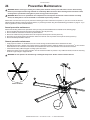
Please take a few moments each year to perform the following preventive maintenance inspection on your fan to ensure its safe and
HI¿FLHQWRSHUDWLRQ%HIRUHFRQWDFWLQJ&XVWRPHU6HUYLFHWU\UHVROYLQJWKHLVVXHXVLQJWKHWURXEOHVKRRWLQJSURFHGXUHVRQSDJH,I\RX
KDYHDQ\TXHVWLRQVFRQWDFW&XVWRPHU6HUYLFH
Annual preventive maintenance
3HUIRUPWKHIROORZLQJPDLQWHQDQFHSURFHGXUHVHDFK\HDUXVLQJWKH$QQXDO0DLQWHQDQFH&KHFNOLVWRQWKHIROORZLQJSDJH
Ensure all upper PRXQWLQJEROWVDUHSUHVHQWDQGWRUTXHGWRIWāOE1āP
EnsureDLUIRLOVDUHVHFXUHGWRRQHDQRWKHUE\DLUIRLOUHWDLQHUV
(QVXUHDOOEROWVVHFXULQJWKHDLUIRLOVWRWKHIDQDUHSUHVHQWDQGtorqued toIWāOE1āP
(QVXUHWKHWZREROWVVHFXULQJWKHH[WHQVLRQWXEHWRWKHPDLQIDQXQLWDUHpresent and torqued to IWāOE1āP
(QVXUHDOODLUIRLOWLSKDUGZDUHLVVHFXUH
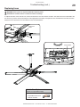
General preventive maintenance
• 9HULI\SURSHUIDQURWDWLRQ7REHHIIHFWLYHWKHIDQPXVWEHWXUQLQJFRXQWHUFORFNZLVHZKHQYLHZHGIURPWKHÀRRU
• 'XVWDLUIRLOVDQGPRWRU,IGHVLUHGXVHDJHQWOHFOHDQHURUGHJUHDVLQJDJHQWWRSROLVKWKHDLUIRLOV'RQRWXVH&ORUR[® or other chlorine
EDVHGFOHDQHUV7KLVFRXOGUHVXOWLQWKHUHOHDVHRIWR[LFIDWDOIXPHV'RQRWXVHFOHDQVHUVRQWKHHOHFWURQLFVHQFORVXUH
• &KHFNWKDWWKHVDIHW\FDEOHDQGXSSHUPRXQWLQJV\VWHPDUHVHFXUH
• 2EVHUYHWKHPRWLRQRIWKHIDQGXULQJRSHUDWLRQ7KHIDQVKRXOGQRWZREEOHRUSUHFHVV,IDQ\ZREEOHLVQRWLFHGHQVXUHWKHPRXQWLQJ
VWUXFWXUHLVULJLGHQRXJKWRVXSSRUWWKHIDQ
WARNING: Do not operate a fan with missing or damaged components. Please contact Customer Service.
1
5
4
View from Below
3
2
WWW.BIGASSFANS.COM
©2014 DELTA T CORP.
ALL RIGHTS RESERVED
Annual Maintenance Checklist
Fan Model:
Fan Model:
Fan Model:
Serial #:
Serial #:
Serial #:
Location:
Location:
Location:
Date
Initials
Date
Initials
Date
Initials
BIG ASS FAN 2025
Troubleshooting
27
WARNING: When servicing or replacement of a component in the fan requires the removal or disconnection of a safety
device, the safety device is to be reinstalled or remounted as previously installed.
CAUTION: Use this unit only in the manner intended by the manufacturer. If you have questions, contact the manufacturer.
WARNING: Before servicing or cleaning unit, switch power off at the service panel and lock the service disconnecting
means to prevent power from being switched on accidentally. When the service disconnecting means cannot be locked,
securely fasten a prominent warning device, such as a tag, to the service panel.
General troubleshooting
)RUTXHVWLRQVDERXW\RXUSURGXFWRUFXVWRPHUVHUYLFHLQTXLULHVSOHDVHFDOORXUWROOIUHHQXPEHU%,*)$16
6RPHLVVXHVFDQEHUHVROYHGEHIRUHUHTXHVWLQJVHUYLFH5HYLHZWKHEHORZWURXEOHVKRRWLQJWLSVEHIRUHFRQWDFWLQJ&XVWRPHU6HUYLFHIRU
VXSSRUW
Symptom
Possible solution(s)
A popping noise is coming from the fan.
6ZLWFKRIISRZHUDWWKHVHUYLFHSDQHODQGORFNWKHVHUYLFHGLVFRQQHFWLQJPHDQV,ILW
FDQQRWEHORFNHGIDVWHQDSURPLQHQWZDUQLQJGHYLFH7LJKWHQWKHDLUIRLOKDUGZDUHWR
IWāOE1āP,ISRSSLQJVWLOORFFXUVYHULI\WKDWWKHDLUIRLOVDUHQRWFRQWDFWLQJHDFK
RWKHU,IWKHDLUIRLOVDUHFRQWDFWLQJHDFKRWKHUSOHDVHFRQWDFW&XVWRPHU6HUYLFH
Airfoil noise is a result of airfoils that are
QRWWLJKWHQHGWRWKHVSHFL¿HGWRUTXH
Verify the following:
• $OOZLUHVDUHVHFXUHO\FRQQHFWHG
• 7KHEOXHZLUHDQGWKH\HOORZZLUHRQWKHFRQWUROOHULQSXWFDEOHDUHZLUHGWRJHWKHU
6HHSDJHV±IRUZLULQJGHWDLOV
• 7KHZDOOFRQWUROOHUKDVSRZHU
• 6XSSO\SRZHULVDGHTXDWHDQGIXQFWLRQDO
• $OOIXVHVDUHIXQFWLRQDO,IDIXVHLVEORZQVHHSDJHIRULQVWUXFWLRQVRQUHSODFLQJ
IXVHV
The fan will not start.
,IWKHIDQVWLOOGRHVQRWVWDUWFRQWDFW&XVWRPHU6HUYLFH
7KH/('RQWKHZDOOFRQWUROOHULVÀDVKLQJ
6HHWKHIROORZLQJSDJHIRUIDQHUURUFRGHGHVFULSWLRQVDQGSRVVLEOHVROXWLRQV
7KH/('RQWKHZDOOFRQWUROOHUZLOOÀDVK
DQHUURUFRGHLIWKHUHLVDSUREOHPZLWKWKH
IDQ
The fan jerks upon startup.
7KLVLVQRUPDODQGPD\KDSSHQRFFDVLRQDOO\XSRQVWDUWXSDVWKHIDQSRVLWLRQVLWVHOI
UHODWLYHWRWKHPRWRUVWDWRU$QLQLWLDOVOLJKWMHUNLQJIRUZDUGDQGEDFNZDUGGRHVQRWDIIHFW
IDQRSHUDWLRQ
WWW.BIGASSFANS.COM
©2014 DELTA T CORP.
ALL RIGHTS RESERVED
BIG ASS FAN 2025
7URXEOHVKRRWLQJFRQW
28
Electrical troubleshooting
)DQVWDWXV/('GH¿QLWLRQV
7KHIDQGLUHFWLRQVHOHFWRUVZLWFKDQGIDQVWDWXV/('DUHORFDWHGRQWKHFRYHUSODWHDVVHPEO\DWWKHERWWRPRIWKHIDQ¶VH[WHQVLRQWXEH
Fan Direction
6HOHFWRU6ZLWFK
&RYHU3ODWH
$VVHPEO\
)DQ6WDWXV/('
Note: For information on changing
the fan direction, see page 22.
LED status:
'H¿QLWLRQ
2QH6HFRQG)ODVK6HFRQGV2II
2YHU7HPSHUDWXUH
7ZR6HFRQG)ODVKHV6HFRQGV2II
0RWRU6WDOO
7KUHH6HFRQG)ODVKHV6HFRQGV2II
Output Device Failure
)RXU6HFRQG)ODVKHV6HFRQGV2II
,QWHUQDO&RPPXQLFDWLRQ(UURU
)LYH6HFRQG)ODVKHV6HFRQGV2II
'&%XVV8QGHUYROWDJH
6L[6HFRQG)ODVKHV6HFRQGV2II
'&%XVV2YHU9ROWDJH
6HYHQ6HFRQG)ODVKHV6HFRQGV2II
5XQ(QDEOH-XPSHU2SHQ
(LJKW6HFRQG)ODVKHV6HFRQGV2II
0RWRU2YHUORDG7KHUPDO7ULS
1LQH6HFRQG)ODVKHV6HFRQGV2II
&XUUHQW/LPLW6KRUW&LUFXLW
Fan status LED troubleshooting
LED code
Description/Possible cause(s)
2YHU7HPSHUDWXUH
7KHIDQGULYHHOHFWURQLFVKDYHH[FHHGHGVDIHRSHUDWLQJ
WHPSHUDWXUHOLPLWV
Output Device Failure
7KHIDQGULYHHOHFWURQLFVKDYHIDLOHGRURXWSXWSKDVH
ORVVKDVRFFXUUHG
,QWHUQDO&RPPXQLFDWLRQ(UURU
7KHPDLQIDQGULYHKDVIDLOHGWRUHVSRQGWRWKH
FRPPDQGVRXUFHGDXJKWHUERDUGHWF
'&%XVV8QGHUYROWDJH
%XVVYROWDJHKDVIDOOHQEHORZ9'&
'&%XVV2YHU9ROWDJH
%XVVYROWDJHKDVH[FHHGHG9'&
0RWRU2YHUORDG7KHUPDO7ULS
7KHUPDOPRWRURYHUORDGSURWHFWLRQKDVEHHQDFWLYDWHG
&XUUHQW/LPLW6KRUW&LUFXLW
7KHKDUGZDUHFXUUHQWOLPLWKDVEHHQUHDFKHG$VHYHUH
RYHUORDGRUVKRUWFLUFXLWFRQGLWLRQH[LVWVRQWKHIDQGULYH
RXWSXW
0RWRU6WDOO
7KHIDQIDLOHGWRDFFHOHUDWHWRWKHWDUJHW530ZLWKLQRQH 7KHIDQZLOOVKXWGRZQDQGZLOOQRWDWWHPSW
PLQXWHRIVWDUWXS
WRUHVWDUW&RQWDFW&XVWRPHU6HUYLFH
5XQ(QDEOH-XPSHU2SHQ
7KHUXQHQDEOHFLUFXLWLVRSHQDQGPRWRURSHUDWLRQLV
GLVDEOHG
WWW.BIGASSFANS.COM
©2014 DELTA T CORP.
Possible solution(s)
7KHIDQZLOOVKXWGRZQIRU¿YHPLQXWHV
DQGWKHQDWWHPSWWRUHVWDUWWZRWLPHV,I
WKHIDQGRHVQRWUHVWDUWDIWHUWZRDWWHPSWV
UHVHWSRZHUWRWKHIDQ,IWKHIDQVWLOOGRHV
QRWUHVWDUWFRQWDFW&XVWRPHU6HUYLFH
0DNHVXUHWKHEOXHZLUHDQGWKH\HOORZ
ZLUHRQWKHFRQWUROOHULQSXWFDEOHDUHZLUHG
WRJHWKHU6HHSDJHV±IRUZLULQJGHWDLOV
ALL RIGHTS RESERVED
BIG ASS FAN 2025
7URXEOHVKRRWLQJFRQW
29
Replacing fuses
WARNING: Ensure power is disconnected before replacing fuses.
CAUTION: Do not touch the fan’s electronics unless necessary!
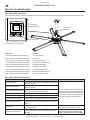
7RUHSODFHWKHIXVHVRQWKHPDLQIDQXQLWUHPRYHWKHHOHFWURQLFVFRYHUIURPWKHIDQDVVKRZQ7KHHOHFWURQLFVFRYHULVDWWDFKHGWRWKH
IDQZLWKIRXUVFUHZV*HQWO\WZLVWDQGSXOORXWWKHDSSURSULDWHIXVHKROGHUDQGUHSODFHWKHIXVH5HLQVWDOOWKHIXVHKROGHUDQGWKHQ
UHDWWDFKWKHIDQ¶VHOHFWURQLFVFRYHU6HHEHORZIRUIXVHUHFRPPHQGDWLRQV
Electronics
&RYHU
Fuse Holders
Suitable Fuse Replacements
9$&$$&0DLQV6XSSO\
• Schurter 0034.2526
• &RRSHU%XVV65
• /LWWHOIXVH
WWW.BIGASSFANS.COM
©2014 DELTA T CORP.
ALL RIGHTS RESERVED
BIG ASS FAN 2025
30
Warranty Policy
Congratulations on your purchase of a Big Ass Fan! We are delighted that you have chosen our product to improve the quality of your
indoor or outdoor environment, and hope you’ll have much pleasure using the fan for years to come.
Warranty period
Item
Period of coverage
Hub and airfoils
Lifetime (parts)
Motor and controller
1 year (parts)
All other fan components
1 year (parts)
What is covered?
This Warranty covers any defects in materials or workmanship under normal use and maintenance that adversely affect the ability of
the fan to operate properly when the product is installed correctly according to Big Ass Fans’ written installation instructions by a state
TXDOL¿HGRUOLFHQVHGHOHFWULFDOFRQWUDFWRUDQGRSHUDWHGSXUVXDQWWRWKHVHLQVWUXFWLRQVDQGZKHQVXFKIDQVDUHSXUFKDVHGGLUHFWO\IURP
Big Ass Fan Company, Big Ass )DQV¶$I¿OLDWHG&RPSDQLHVLQ$XVWUDOLDRUD%LJAss Fan Company Authorized Dealer. This Limited
Warranty is subject to all provisions, conditions, limitations, and exclusions described within this document.
Who is covered?
This Warranty extends to the original purchaser and subsequent owners, but only while the fan remains at the site of the original
LQVWDOODWLRQ7KLV:DUUDQW\H[WHQGVWKURXJKWKH¿UVWLQVWDOODWLRQRIWKHIDQDQGWHUPLQDWHVLIWKHIDQLVPRYHGRUUHLQVWDOOHGDWDQHZ
location.
When does the Warranty Period begin?
The Warranty Period commences on the date the product is installed, or 15 days following shipment of the product, whichever date is
earlier. To obtain warranty service, the customer will be required to provide documentation verifying the date the product was installed.
What will Big Ass Fans do?
1. During the Warranty Period, Big Ass Fans will, at its option:
a. Repair or replace the affected components of any defective product;
b. Repair or replace the defective product; or
c. Refund the price you paid for the product upon return of the product to Big Ass Fans, shipping and insurance prepaid.
What are the steps required to obtain Warranty service?
1. If the fan is operating, immediately turn off the fan.
2. Contact Big Ass Fans’ Technical Support Department as soon after the issue is discovered as possible by:
a. Calling 1-877-BIG-FANS (244-3267); or
b. Going online to www.bigassfans.com/technical-support and completing a Technical Service form; or
c. Completing the Warranty Claim form and the Responsibility Agreement located in the back of the Installation Manual, and mailing
the forms to Big Ass Fans Technical Support Department, 2348 Innovation Drive, Lexington, KY 40511, or by faxing them to
859-967-1695.
Technical Support is open from 8:00 a.m. to 5:00 p.m. Eastern Time, Monday–Friday, excluding major holidays. Every effort will be
made to respond to all Technical Support requests within 24 hours of receipt.
3. Once the Technical Support Representative has received your warranty claim, a case will be processed. In order to process this
case, please have the following information available:
a. Your name, address, phone number, and installation address;
b. 3URGXFWEUDQGQDPHVHULDOQXPEHUSXUFKDVHSULFHDQGYHUL¿FDWLRQRISURGXFWLQVWDOODWLRQRUSUHPLVHVSRVVHVVLRQGDWH
c. Detailed description of the problem you have experienced.
4. If the Technical Support Representative determines that the warranty claim is valid and that a replacement part is required, the
Representative will process the claim and the replacement part will be shipped to you. Included in the shipment of the replacement
part will be any shipping labels and documents needed to return the original part, including a Return Materials Authorization (RMA)
number.
WWW.BIGASSFANS.COM
©2014 DELTA T CORP.
ALL RIGHTS RESERVED
BIG ASS FAN 2025
Warranty Policy (cont.)
31
Steps to obtain Warranty service (cont.)
Note: Your receipt of the replacement part constitutes your agreement to return the failed part to Big Ass Fans within 15 days of the
receipt of the replacement part delivery. If Big Ass Fans does not receive the original part, you will be invoiced for the retail cost of the
replacement part and shipping, and you will be responsible for payment for the replacement part upon receipt of the invoice. Big Ass
Fans reserves all rights it retains under law to collect the retail cost of the replacement part and shipping if the original is not returned
DVVSHFL¿HGDERYH
5. Obtaining service may involve contacting a contractor to remove, repair, or replace the fan, or to remove the fan and return it to us.
7KHFRVWRIODERULQFXUUHGIRUIDFWRU\LQVWDOOHGIDQVWRUHPRYHUHSDLURUUHLQVWDOOWKHIDQVZLOOEHFRYHUHGRQO\GXULQJWKH¿UVW
PRQWKVDIWHUWKHZDUUDQW\EHFRPHVHIIHFWLYHDQGRQO\SXUVXDQWWRWKHWHUPVRIWKHGH¿QLWLRQRI³/DERU´EHORZ
6. If we ask you to ship the fan back to Big Ass Fans for repairs or replacement, we will prepay the shipping and insurance for factory
LQVWDOOHGIDQVGXULQJWKH¿UVWPRQWKVDIWHUWKHZDUUDQW\EHFRPHVHIIHFWLYHKRZHYHU\RXZLOOKDYHWRUHSDFNDJHWKHIDQLQVXFKD
way that there is no damage to the fan in transit. You will be sent any return shipment documentation necessary to help you return
the fan to Big Ass Fans. If we determine that no warrantable failure occurred or defect exists, we may invoice you for these shipping
costs.
Please be patient while we arrange for or undertake the necessary warranty service. We will provide you with regular status updates,
as well as shipment dates, if appropriate, until your fan is back in service.
Conditions
1. Big Ass )DQ&RPSDQ\UHVHUYHVWKHULJKWWRPDNHWKH¿QDOGHWHUPLQDWLRQEDVHGRQLWVRZQHYDOXDWLRQRIWKHIDQDQGDOOFRPSRQHQWV
as to whether:
a. The problem in question is the result of a defect in design, workmanship, or materials, and not a result of error, misuse, or abuse
on the part of the customer as set forth under the exclusions detailed below;
b. Noise heard during operation is within normal operating levels, in which case this Warranty would be inapplicable. Note:
Certain electrical, motor, or other operating noise may be impossible to eliminate due to the fan design and/or site conditions.
Dissatisfaction with normal operating noise levels is not covered by this Warranty, and return of any fans for this reason will be
subject to Big Ass Fans’ Return Policy (see below).
c. Adverse site conditions, (including, but not limited to, excessive dust, heat, humidity, unstable electric service, or any other
unknown or unforeseen condition that affects the proper operation of the products) improper application, or improper installation
is determined to be the basis for the failure.
d. The problem or defect is material and requires action under this warranty; and
e. The remedy of repair, replacement, or refund is appropriate.
2. If Big Ass Fans determines, in its sole discretion, that the appropriate remedy under the Warranty is a refund, the refund amount
will be limited to the price paid by the customer for the product alone, and under no circumstances will it include the cost of labor,
shipping, handling, packaging, or any other incidental or consequential costs incurred or anticipated by the customer.
3. With respect to replacement or repair rendered, Big Ass Fan Company reserves the right to use replacement parts that are
refurbished. Big Ass Fan Company warrants that the parts replaced or repaired, whether or not they have been refurbished or are
original equipment, will operate properly and be free from defects in materials and workmanship for a period of 90 days from the
date of shipment to the customer, or for the remainder of the original warranty period, whichever is longer.
4. A service fee, parts replacement fee, and shipping charges may be imposed if any fan is returned for warranty service that is missing
FRPSRQHQWVRUWKDWKDVEHHQPRGL¿HGLQDQ\ZD\RUZKHQZHGHWHUPLQHWKDWQRZDUUDQWDEOHIDLOXUHRFFXUUHGRUGHIHFWH[LVWV6XFK
IHHVDQGFKDUJHVZLOOYDU\EDVHGXSRQWKHDFWXDOPDWHULDODQGODERUFRVWVQHFHVVDU\WRUHSODFHPLVVLQJRUPRGL¿HGSDUWVDQGWR
return the fan to its original factory condition.
Return policy
Returns must be received within 90 days of shipment. The customer will be responsible for return freight charges. A restocking fee of
25% for unopened boxes and 50% for opened boxes applies to all returns.
What is not covered (exclusions)?
1. Units purchased and used outside the USA and its territories, Canada, or Australia.
2. Units purchased from any entity other than Big Ass Fan Company, Big Ass )DQ$I¿OLDWHG&RPSDQLHVLQ$XVWUDOLDRUD%LJAss Fan
Company Authorized Dealer.
3. Units or components where the serial number or part number sticker has been removed or defaced.
WWW.BIGASSFANS.COM
©2014 DELTA T CORP.
ALL RIGHTS RESERVED
BIG ASS FAN 2025
32
Warranty Policy (cont.)
Exclusions (cont.)
4. Defects, malfunctions, failure or physical damage caused by unauthorized service/parts and improper installation, adverse
site conditions (including, but not limited to, excessive heat, dust or humidity, unstable electric service, or any other unknown
RUXQIRUHVHHQFRQGLWLRQWKDWDIIHFWVWKHSURSHURSHUDWLRQRIWKHSURGXFWVPLVKDQGOLQJPRGL¿FDWLRQVRUGDPDJHZKLOHLQ\RXU
possession including failure to provide reasonable and necessary maintenance, which shall include, but not be limited to:
a. )DLOXUHWRIROORZWKHUHTXLUHGLQVWDOODWLRQSURFHGXUHVVSHFL¿HGLQWKH%LJAss Fan Company-supplied Installation Manual and in all
other documentation supplied with the fans and related equipment;
b. Failure to follow all relevant codes and ordinances including, but not limited to, the National Electric Code and state and local
building codes;
c. Failure to follow electrical engineering industry standards regarding the approved method of installing solid-state electrical
equipment having the characteristics of the fan, the fan control, and their related components, even if such standards are not
VSHFL¿FDOO\UHIHUHQFHGLQDQ\LQVWUXFWLRQVRUOLWHUDWXUHVXSSOLHGE\%LJAss Fan Company; and
d. Failure to use properly all installation and mounting hardware supplied by Big Ass Fan Company.
ATTENTION: Under no circumstances will the Big Ass Fan Company be responsible for remedial work necessary to correct
installation procedures by others that do not conform to those established by the instructions, codes, and standards
described under items 4.a through 4.d above.
e. $Q\PRGL¿FDWLRQRUDOWHUDWLRQRIRUDGMXVWPHQWWRWKHIDQVIDQFRQWURODQGRUPRXQWLQJDQGLQVWDOODWLRQKDUGZDUHDQGRUDQ\
disassembly of the major components of the fans and fan controls for any purpose whatsoever, including any attempt to diagnose
and/or repair any problem, without prior written authorization from Big Ass Fans’ Technical Support Department;
f. Misuse, abuse, accidents, unreasonable use, or Acts of God;
g. Incorrect electric current, voltage, or supply;
h. Failure to use fan controls supplied by Big Ass Fan Company unless:
i. Big Ass Fans’ Technical Support Department has provided written permission prior to installation; and
ii. 7KHIDQFRQWUROVDUHEXLOWRSHUDWHGDQGPDLQWDLQHGDFFRUGLQJWRVSHFL¿FDWLRQVSURYLGHGWRDQGDSSURYHGE\%LJAss Fans’
Technical Support Department.
i. Failure to perform periodic maintenance as detailed in the Big Ass Fan Company-supplied Installation Manual.
5. Consequential or incidental damages sustained by any person, entity, or structure as a result of any breach of these warranties,
except where such damages may not be excluded by law.
6. Claims made for products that have not been paid for in full.
7. Damage caused by premises structural defects, structural movement or settlement, exposure to chemicals, salt water, acid rain or
other corrosive elements, excessive humidity, and/or wind.
8. 1RUPDOFKDQJHVWRWKH¿QLVKFDXVHGE\RUGLQDU\XVHRUGDPDJHWRQRQIDFWRU\DSSOLHG¿QLVKHV
9. Damage or failure caused by subjection of the product to conditions outside its design limitations.
10. Defects reported more than 90 days from when they were discovered or should have been discovered.
11. With regard to electrical and electronic components provided by Big Ass Fan Company that comprise part of the products, including
motors, motor drives, and variable frequency drives, Big Ass Fan Company relies on the determination by the original manufacturer
as to whether the failure of such component was the result of a defect. If the manufacturer of such component determines that
there was no defect and therefore refuses to cover it under warranty, Big Ass Fan Company likewise will not warranty such item
unless Big Ass Fan Company determines that the failure of such electrical or electronic component was the result of a defect of
design, workmanship, or material within some other part of the products.
'H¿QLWLRQV
³2SHUDWHSURSHUO\´DSSOLHVWRPHFKDQLFDOHOHFWULFDODQGVWUXFWXUDOIXQFWLRQVRQO\1RJXDUDQWHHXQOHVVDQGH[FHSWE\VHSDUDWHZULWWHQ
agreement, is made regarding the dimensions or air movement generated or the appropriateness of the effectiveness of any product for
its intended purpose or for the customer’s particular application.
WWW.BIGASSFANS.COM
©2014 DELTA T CORP.
ALL RIGHTS RESERVED
BIG ASS FAN 2025
Warranty Policy (cont.)
33
THIS WARRANTY IS EXPRESSLY IN LIEU OF ALL OTHER WARRANTIES, EXPRESSED OR IMPLIED, INCLUDING
WARRANTIES OF MERCHANTABILITY OR FITNESS FOR PARTICULAR PURPOSE, AND OF ALL OTHER OBLIGATIONS AND
LIABILITIES ON BIG ASS FAN COMPANY’S PART, AND BIG ASS FAN COMPANY NEITHER ASSUMES NOR AUTHORIZES ANY
PERSON TO ASSUME FOR IT ANY OTHER LIABILITY IN CONNECTION WITH THE SALE OF THE PRODUCTS. NO OTHER
WARRANTY, EXPRESSED OR IMPLIED, WHETHER OF FITNESS FOR A PARTICULAR PURPOSE OR OF MERCHANTABILITY
OR OF ANY OTHER KIND, WHETHER OR NOT SIMILAR IN NATURE TO ANY PREVIOUSLY SPECIFIED, SHALL EXIST WITH
RESPECT TO SUCH PRODUCTS, ALL SUCH WARRANTIES BEING HEREBY DISCLAIMED BY BIG ASS FAN COMPANY
AND WAIVED BY CUSTOMER. UNDER NO CIRCUMSTANCES SHALL BIG ASS FAN COMPANY BE LIABLE FOR ANY LOSS,
DAMAGE, COST OF REPAIR, OR INCIDENTAL OR CONSEQUENTIAL DAMAGES OF ANY KIND IN CONNECTION WITH THE
USE, SALE, OR REPAIR OF ANY PRODUCTS PURCHASED FROM BIG ASS FAN COMPANY, UNLESS SUCH DAMAGES
CANNOT BE EXCLUDED BY LAW.
Big Ass Fan Company reserves the right to change this warranty at any time without advance notice.
WWW.BIGASSFANS.COM
©2014 DELTA T CORP.
ALL RIGHTS RESERVED
BIG ASS FAN 2025
34
Warranty Return Instructions
Congratulations on your purchase of a Big Ass Fan! We are delighted that you have chosen our product to improve the quality of your
indoor environment, and hope you’ll have much pleasure using the fan for years to come.
Replacement of products under warranty acknowledgment & return instructions
If you believe a part failed during normal operation and is covered under warranty, Big Ass Fans will ship a replacement part to you
pursuant to your notice that you will be replacing the original part within 10 days. The replacement part will be shipped to you prior to
our receipt of the item that failed, and prior to our evaluation of this part to determine the reasons for its failure and whether it is covered
under warranty.
,QRUGHUWRHYDOXDWHWKHFDXVHRIWKHSURGXFWIDLOXUHZHZLOOQHHG\RXWRUHWXUQWKHRULJLQDOSDUWWRRXURI¿FHVZLWKLQZRUNLQJGD\VRI
receipt of the replacement part. Should the part be covered under warranty, you will not be charged for the replacement item; however,
you will be charged for the replacement part plus shipping if (1) the part is not under warranty because the source of failure is outside
the scope of the warranty, or (2) the warranty period has expired. If there is no warranty coverage, we will send you a detailed letter of
explanation. We also will charge you for the replacement item plus shipping and handling if you do not return the original item within 10
days of the receipt of the replacement item.
Instructions for returning the original item
1. Please use the return label that is included in the box containing the replacement part. The return shipment address is:
Big Ass Fan Company
ATTN: RMA#________
800 Winchester Road
Lexington, KY 40505
2. Use the packaging for the replacement part to return the original part.
3. Include the packing list we have provided which includes the RMA#.
4. If the part weighs over 50 lbs., you will be provided a prepaid Bill Of Lading. To schedule a freight pick up, please contact Customer
Service. We will only charge back the freight costs if the original part is not under warranty, or if you do not return the original
component within 10 days of receipt of the replacement.
5. If the part weighs 50 lbs. or less, please use the provided prepaid UPS Ground shipping label and drop off at your nearest UPS
pickup location.
If you have questions, please contact us at 1-877-BIG-FANS.
WWW.BIGASSFANS.COM
©2014 DELTA T CORP.
ALL RIGHTS RESERVED
BIG ASS FAN 2025
Warranty Return Instructions (cont.)
35
Warranty claim form instructions
1. Complete Warranty Claim Form and Responsibility Agreement (see following pages) and fax them to 859-967-1695, Attn: Customer
Service. These pages will be faxed back to you for your records. The Warranty Claim Form will include our acknowledgment and a
Return Materials Authorization (RMA) number. 'RQRWUHWXUQDQ\LWHPZLWKRXW¿UVWEHLQJDVVLJQHGDQ50$E\%LJAss Fans
Customer Service.
2. No more than 10 days prior to the date you have made arrangements to replace the component part, call Customer Service at
1-877-BIG-FANS to arrange for replacement component delivery and original component pickup. At that time, we will fax you a
written acknowledgment of your call that includes a reminder of the return instructions. Note: Even if you are not able to replace
the component immediately following your initial notice to us, returning the Warranty Claim Form and Responsibility Agreement
will effectively stop the warranty clock from running. You can then make the product exchange when you are prepared to do so.
However, the warranty period will continue to run until we receive these completed pages back from you, and no warranty will be
honored without receipt of these pages within the warranty period. We will not send out any replacement part until you have called to
let us know that you have scheduled installation of the replacement. This ensures that the replacement part is not lost or damaged
while awaiting installation, and that you are not billed for the replacement because you have waited too long to return the original
component (see Responsibility Agreement).
3. When you receive the replacement part, you have 10 working days to remove and replace the existing component and return it to us
at 800 Winchester Road, Lexington, KY 40505.
a. Upon receiving the replacement part, verify that replacement part order is correct. If order is incorrect or damaged, notify Big Ass
Fan Company within 24 hours after receiving order.
b. Use care unpacking the replacement component, as you will need to use both the packaging from the replacement part and the
packing list and a return address label included inside this packaging to return the original part. If the original packaging and
return documents are not used, you will be responsible for any damage incurred in transit as well as any additional costs involved.
Note: 7KH50$PXVWDSSHDURQWKHRXWVLGHRIWKHER[EHLQJUHWXUQHG,WHPVZLWKRXWDQ50$ZLOOQRWEHDFFHSWHG
c. 8VHWKHGHOLYHU\VHUYLFHRURQHRIWKHWUXFNOLQHVVSHFL¿HGLQWKHDFNQRZOHGJHPHQWIRUUHWXUQRIWKHSDUW:HZLOOUHIXVHUHFHLSWRI
any shipment that is returned via an unauthorized carrier. If you prefer, we can make all arrangements for delivery and pickup.
d. Fax a copy of the bill of lading or other tracking information to 859-967-1695 when the item has been shipped so that we know to
expect delivery of the original part.
4. If we do not receive the original part back within 15 working days from the date you receive delivery of the replacement, you will be
invoiced for the cost of the replacement part, plus freight, on Net 15 terms (see Responsibility Agreement), and this invoice will be
due and payable. If you subsequently return the replacement part to us after payment has been made, we will refund any payment
made for the replacement part, unless we subsequently determine that the part is not covered under warranty.
WWW.BIGASSFANS.COM
©2014 DELTA T CORP.
ALL RIGHTS RESERVED
800 Winchester Road
Lexington, KY 40505
Phone: 1-877-BIG-FANS
Fax: (859) 967-1695
www.bigassfans.com
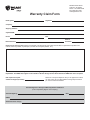
Warranty Claim Form
Name (print):
Signature:
Company:
Shipping Address:
City/State/ZIP:
Phone:
Fax:
Date of
Purchase:
Items Returned:
Reason(s) for returning item (please provide detail, including length of time after fan had been in operation that problem was
noticed, nature of problem, any attempts you made to remedy the problem, etc.):
$77(17,21'RQRWUHWXUQDQ\LWHPZLWKRXW¿UVWEHLQJDVVLJQHGDQ50$E\%LJAss Fan Company Customer Service
'HSDUWPHQW7KH50$PXVWDSSHDURQWKHRXWVLGHRIWKHER[EHLQJUHWXUQHG,WHPVZLWKRXWDQ50$ZLOOQRWEHDFFHSWHG
Date replacement parts
should be shipped (if known):
Please do not request shipment until you are prepared to install;
you may call us at 1-877-BIG-FANS to arrange shipment when
you have scheduled installation.
$FNQRZOHGJPHQWRI5HFHLSWRI:DUUDQW\5HWXUQ1RWL¿FDWLRQ
(to be completed by Big Ass Fan Company)
Acknowledged by:
50$
Authorized Truck Line(s):
Date:
800 Winchester Road
Lexington, KY 40505
Phone: 1-877-BIG-FANS
Fax: (859) 967-1695
www.bigassfans.com
Responsibility Agreement
To: Big Ass Fan Company
The undersigned understands and acknowledges receipt of the Warranty Claim Form and Instructions and agrees that Big Ass Fan
&RPSDQ\KDVWKHULJKWXSRQUHFHLSWRIUHWXUQHGPHUFKDQGLVHWRPDNH¿QDOGHWHUPLQDWLRQDVWRZKHWKHUWKLVPHUFKDQGLVHVKRXOGEH
replaced at no cost under Big Ass Fan Company’s stated warranty policy.
The undersigned further agrees that if Big Ass Fan Company determines that this merchandise does not qualify under its stated
warranty policy, Big Ass Fan Company can invoice for the replacement merchandise, plus shipping and handling for the original part
and all replacements, and such invoice will be paid within 15 days of receipt of the same.
The undersigned agrees to ship to Big Ass Fan Company’s location at 800 Winchester Road, Lexington, KY 40505 all of the
merchandise replaced by Big Ass Fan Company, including, but not necessarily limited to, defective or failed components, within 10
working days of the receipt of the any replacements.
The undersigned further agrees that if said replaced merchandise has not been shipped to Big Ass Fan Company within 10 working
days, Big Ass Fan Company can invoice for the replacement merchandise plus shipping and handling, and the invoice will be paid
within 15 days of receipt.
Signed:
Title:
For:
(Name of Company)
Date:
*004465-01*
004465-01
REV. A
2425 Merchant St., Lexington, KY 40511
1 (877) BIG-FANS | WWW.BIGASSFANS.COM