1
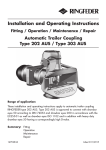
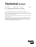
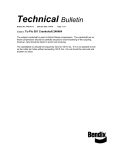
204-07_Aus_Type 101
04.18.2007
16:12 Uhr
Seite 1
Trailer Couplings
Installation and Operating Instructions
Fitting / Operation / Maintenance / Repair
Automatic Trailer Coupling
Type 101 AUS
Range of application:
These installation and operating instructions apply to automatic trailer coupling
RINGFEDER type 101 AUS. Type 101 AUS is approved to connect with drawbar
eyes 50 according to DIN 74053 and drawbar eyes D50 in accordance with the
EU directive 94/20 and ECE55-01 as well as drawbar eyes ISO 1102 and in
addition with heavy duty drawbar eyes 50 having a correspondingly high D-value.
Summary: Fitting
Operation
Maintenance
Repair
10069949
04/2007
204-07_Aus_Type 101
04.18.2007
16:12 Uhr
Seite 2
Installation
1.
Remove castle nut (42).
2.
Pull tension washer (40), rubber spring (36) and bar guide (38) from the
drawbar (1).
3.
Fit bar guide (38) contrary to the driving direction to the inner face of the rear
drawbeam.
Caution: Max thickness of the drawbeam: 35 mm!
4.
Tighten the bar guide (38) together with the drawbeam using 4 bolts grade 8.8
and 4 safety nuts grade 8. The heads of the screws have to be mounted on the
side of the coupling head (outer side of the drawbeam). Under screws and nuts
you have to use washers DIN 125, hardness min 200HV.
Bolt length:
bolt shank
+ washer thickness
+ nut length
+ at least 2 threads
Flange Design
e1xe2 [mm]
d2
[mm]
Thread
(standard thread)
Tightening Torque
Wrench Size
[mm]
160 x 100
Ø 21
M20
410 Nm
30
5.
Fit tension washer (40) without any other components of the towing device to
the bar guide (1) and fully tighten the castle nut (42) by hand. Measure the
dimension X (see figures 1 – 4). Remove castle nut (42) and tension washer (40)
again.
6.
Fit the coupling head assembly including the front rubber spring (36) and thrust
washer (37) to the bar guide (38). If required, regrease drawbar (1) and contact
surfaces of thrust washer (37) and bar guide (38).
Caution: Never grease the rubber spring!
7.
Fit the rear rubber spring (36) and tension washer (40).
Caution: Never grease the rubber spring!
8.
Grease the contact surfaces of the castle nut (42) and tension washer (40). Screw
on and tighten the castle nut (42) until the previously measured dimension X is
reached again and secure by means of a cotter pin (43). Min. tightening torque
of the castle nut M45x3: 700 Nm using a wrench or nut with a wrench size of
70 mm.
To reach the dimension X and the next hole position for the cotter pin
even higher tightening torques may be required.
Caution: Always tighten to the next hole position.
2
9.
Fit and push on the protective plastic cap (44) carefully.
10.
Straighten the coupling.
11.
For a retro-fit please refer to the relevant statutory regulations.
204-07_Aus_Type 101
04.18.2007
16:12 Uhr
Seite 3
Figures 1-4
3
204-07_Aus_Type 101
04.18.2007
16:12 Uhr
Seite 4
Operation
1.
The trailer coupling is closed and secured, resp. coupled that is to say the
towing eye is inserted, the coupling bolt in its lower position, the safety device
is engaged, the safety bar/bolt locates over the coupling bolt, the securing knob
is in its internal engaged position.
2.
Releasing and opening of the trailer coupling:
The coupling can only be opened when the coupling jaw is in the central position or in the lateral end positions. To release the trailer coupling the securing
knob is pulled out and turned ahead until it has reached its external engaged
position. The trailer coupling now is released (Fig. 1). To open the coupling the
hand lever is moved to its upper end position and then released. This will cause
the coupling bolt to lift up and the towing eye may be extended. Due to the
extension of the towing eye the coupling mechanism is again released and thus
the coupling repeatedly closed and secured.
3.
Opening the trailer coupling to couple the towing eye:
To open the trailer coupling proceed as described under item 2 above. The
coupling lever is in its upper end position, the coupling is set ready for its next
engagement. When inserting the towing eye, the coupling mechanism is
released by lifting the coupling bolt. The coupling closes automatically, which
means that the coupling bolt is inserted through the towing eye bush in its
lower position in the guide bush. The safety device is engaged, that is to say
that the safety bar/bolt locates over the coupling bolt, the securing knob is in its
internal engaged position, the coupling is closed and secured, the towing eye is
engaged (Fig. 2).
Check that after each coupling process the safety device is fully engaged. If the
securing knob is not in its internal engaged position, the trailer coupling is
unsecured and the whole procedure must be repeated.
Fig. 1
Trailer coupling
disengaged/uncoupled
4
Fig. 2
Trailer coupling
closed and secured
204-07_Aus_Type 101
04.18.2007
16:12 Uhr
Seite 5
Service and maintenance
It is most important to always realize that the trailer coupling is a safety part and be
handled as such. Regular service, maintenance and lubrication is a prerequisite for a
safe and long-term troublefree service-life. The degree of loading and thus the wear
of a trailer coupling also depend on the type of trailers, the loads, roads and climatic
conditions.
The wear limits given under „safety check“ must not be fallen short of ( for example
coupling bolt diameter) nor exceeded (for example bore hole diameter bottom guide
bush). If daily inspection of the vehicle in operation shows that the function of the
trailer coupling has been impaired or strong signs of wear are sensible it is imperative
that a safety check as described below be carried out immediately and, if necessary,
the specific wearing parts be exchanged.
In order to limit the degree of wear on the coupling bolt and drawbar eye bush these
components must always be kept clean and lubricated. In case of hard running of the
coupling mechanism the coupling head has to be lubricated over the tapered grease
nipple (5).
The trailer coupling should as far as possible not be cleaned by a steam cleaner (high
pressure cleaner). If this cannot be avoided the trailer coupling itself should be closed
beforehand. After such cleaning the bearings of the coupling body should be greased
with WD40 or a similar high-grade permanent lubricant. After that also the coupling
bolt is to be greased and the coupling head be lubricated over the tapered grease
nipple (5).
Safety check
On its safety check the trailer coupling is to be inspected as described below:
Functional check by repeatedly opening and closing the coupling.
1.
Clean coupling bolt (23) and measure its smallest outside diameter in the bulged
area.
Wear limit of coupling bolts (in accordance with ISO-standard)
50 mm bolt couplings: 46,5 mm
Should the wear limit be reached the coupling bolt and the pertaining locking
springs (25), included in the delivery of the coupling bolt have to be replaced by
new ones.
2.
Measure axial play of the coupling bolt (23).
For this purpose close the trailer coupling and push the coupling bolt from
underneath upward by means of an appropriate tool. If the axial play should
exceed 5 mm the hand lever/locking lever assembly has to be replaced.
3.
Control clearance of the coupling bolt (23) in the bottom guide bush (6).
The maximum admissible clearance must not exceed 2,5 mm. If necessary, the
coupling bolt plus pertaining locking springs (25) or the bottom guide bush,
resp. or both have to be replaced by new ones.
Control max. diameter of the bottom guide bush (6) in the area of the coupling
bolt seat e.g. by means of a slide gauge.
Admissible inner dia:
max. 36,5 mm
Should the wear limit be reached the bottom guide bush has to be replaced by a
new one.
5
204-07_Aus_Type 101
04.18.2007
16:12 Uhr
Seite 6
4.
Control bearing clearance of the drawbar (1) in the drawbar guide (38).
Should the clearance between drawbar shaft and bearing bush (39) exceed 1 mm
the plastic bearing bushes (39) in the bar guide (38) have to be replaced.
Together with these also the rubber springs (36) should be replaced by new ones.
5.
Control wear of the wear plate (7).
The wear plate should be kept cleanest possible and free from grease, as grease
consolidates dust and thereby the wear considerably increases due to the
abrasive effect in trailer operation. If the wear plate shows strong signs of wear
and tear (4 mm and more) it has to be replaced by a new one.
6.
Control axial play (longitudinal play) of the bearing.
For this purpose vigorously move the drawbar (not the guiding funnel of the
mouth) back and forth in longitudinal direction using both hands. There must
not be any axial play (longitudinal play) between the drawbar (1) and the bar
guide (38), otherwise the rubber springs (36) have to be replaced.
When replacing the rubber springs, at the same time the plastic bearing bushes
(39) in the bar guide (38) have to be exchanged as well.
7.
Control pivot bearing of the coupling body (3) for longitudinal play.
maximum admissible longitudinal play at the upper bearing: 1 mm
maximum admissible longitudinal play at the lower bearing: 1 mm
When the maximum admissible bearing clearances have been reached the trailer
coupling must be repaired.
8.
Control coupling body (3) for smooth running.
For this purpose move coupling body with the trailer coupling closed to the right
and to the left. In case of stiffness the bearings of the coupling body have to be
roughly cleaned and greased with WD 40 or a similar high-grade permanent
lubricant so that the coupling mouth is smoothly running. By the force of the
return spring the coupling body must automatically return / recoil into its central
position.
Important note: To fix the castellated nut with a cotter pin attend to always
using new, corrosion-resisting cotter pins. Moreover, when replacing component parts of the trailer coupling only original RINGFEDER spare parts are to
be used, since otherwise a safe performance cannot be safeguarded and
every guarantee ceases.
max. 4mm
Pivot bearings of the coupling body
5
6
1
4
2
3
6
(7,8)
204-07_Aus_Type 101
04.18.2007
16:12 Uhr
Seite 7
Repair
Disassembly from the vehicle
1. Remove protecting cap (44) (fig. 1).
2. Remove cotter pin (43) (fig. 2).
3. Unscrew castellated nut (42) (fig. 3).
4. Completely pull out coupling head from the bar guide (38) (fig. 4).
5. Remove tension washer (40) and rubber spring (36) from the bar guide (38).
6. Remove thrust washer (37) and rubber spring (36) from the drawbar shaft (fig. 4).
Stripping down of the coupling head
1. Detach and remove fastening parts (32 – 34 and (9) of the top cap (26) (fig. 5).
2. Disassemble locking springs (25) and coupling bolt (23) including lifting sleeve
(24) (fig. 6/7).
3. Remove wear plate (7) from the coupling mouth.
4. Detach hexagonal screws (14) at the tab washer (12) (fig. 8).
5. Remove tab washer (12) and return spring (11) (fig. 8).
6. Remove bottom guide bush (6) (fig. 9).
7. Remove coupling body (3) with the remaining fitted parts from the drawbar (1)
(fig. 10).
8. Remove top guide bush (2) (fig. 11).
Assembly of the coupling head
1. Drive in top guide bush (2) to the drawbar (1) (fig. 11).
2. Fit coupling body (3) on to the drawbar (1) (fig. 10).
3. Grease bottom guide bush (6) and drive through coupling mouth into the draw
bar. (The threaded holes of the bottom guide bush must be transverse to the
longitudinal axis of the coupling) (fig. 9).
4. Insert return spring (11) (fig. 8).
5. Screw on tab washer (12) (fig. 8).
6. Insert wear plate (7) in coupling mouth and screw up.
7. Insert coupling bolt (23) including lifting sleeve (24) the way that the axis of the
pin (24) is transverse to the longitudinal axis of the coupling (fig. 7).
8.
Insert locking springs (25) (fig.6).
9. Fill in new grease into the housing.
10. Refit top cap (26) and screw up (fig. 6).
11. Slip on rubber spring (36) and thrust washer (37) to the drawbar (1) (fig. 5).
12. Grease drawbar shaft.
Assembly to the vehicle:
1. Grease bearing surface of the thrust washer (37) on the bar guide (38).
2. Fit tension washer (40) without any other components of the towing device to
the bar guide (1) and fully tighten the castellated nut (42) by hand. Measure the
dimension X (see figures 1 – 4). Remove castellated nut (42) and tension washer
(40) again.
3. Fit the complete coupling head assembly to the bar guide (38) (fig. 4).
4. Slip on rubber spring (36) and tension washer (40) to the drawbar shaft.
5. Screw on castellated nut (42) and tighten according to "fitting instructions - item
8" (fig. 3).
7
204-07_Aus_Type 101
6.
7.
8.
04.18.2007
16:12 Uhr
Seite 8
Drive in new cotter pin (43) and secure properly (fig. 2).
Slip on protecting cap (44) (fig. 1).
If necessary, adjust coupling head horizontally to the vehicle by using a lever.
Caution: Never grease the rubber springs!
Important Note: To fix the castellated nut with a cotter pin attend to always
using new, corrosion-resisting cotter pins.
Moreover, when replacing component parts of the trailer coupling only original RINGFEDER® spare parts are to be used, since otherwise a safe performance cannot be safeguarded and every guarantee ceases.
8
204-07_Aus_Type 101
04.18.2007
16:12 Uhr
Seite 9
9
204-07_Aus_Type 101
10
04.18.2007
16:12 Uhr
Seite 10
204-07_Aus_Type 101
04.18.2007
16:12 Uhr
Seite 11
Trailer Couplings
A certified company in accordance with DIN EN ISO 9001:2000 and ISO TS 16949:2002
and DIN EN ISO 14001:1996
VBG GROUP TRUCK EQUIPMENT GMBH
Oberschlesienstr. 15 · D-47807 Krefeld · Postfach/POB 13 06 55 · D-47758 Krefeld
Phone +49 (0) 21 51 8 35-0 · Facsimile +49 (0) 21 51 8 35-200
www.ringfeder.de · [email protected]
11
04.18.2007
16:12 Uhr
Seite 12
Trailer Couplings
204-07_Aus_Type 101