1
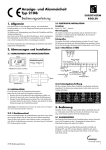
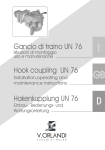
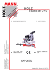
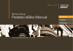
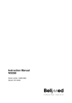
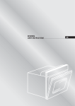
Trailer Couplings
Installation and Operating Instructions
Fitting / Operation / Maintenance / Repair
Automatic Trailer Couplings
Type 5055 AUS, type 5055 NZ, versions A and AP
Range of application:
These installation and operating instructions apply to automatic trailer couplings
RINGFEDER type 5055 AUS and type 5055 NZ. Both types are approved to
connect with drawbar eyes 50 according to DIN 74053 and drawbar eyes D50
in accordance with the EU directive 94/20 and ECE 55R-01 as well as drawbar
eyes ISO 1102 and in addition with heavy duty drawbar eyes 50 having a
correspondingly high D-value.
Summary: Fitting
Operation
Maintenance
Repair
10080019
03/2008
Installation
1.
Remove castle nut (42).
2.
Pull tension washer (40), rubber spring (36) and bar guide (38) from the
drawbar (1).
3.
Fit bar guide (38) contrary to the driving direction to the inner face of the rear
drawbeam.
Caution: Max thickness of the drawbeam: 35 mm!
4.
Tighten the bar guide (38) together with the drawbeam using 4 bolts grade 8.8
and 4 safety nuts grade 8. The heads of the screws have to be mounted on the
side of the coupling head (outer side of the drawbeam). Under screws and nuts
you have to use washers DIN 125, hardness min 200HV.
Bolt length:
bolt shank
+ washer thickness
+ nut length
+ at least 2 threads
Flange Design
e1xe2 [mm]
d2
[mm]
Thread
Tightening Torque
(standard thread)
Wrench Size
[mm]
160 x 100
Ø 21
M20
30
410 Nm
5.
Fit tension washer (40) without any other components of the towing device to
the bar guide (1) and fully tighten the castle nut (42) by hand. Measure the
dimension X (see figures 1 – 4). Remove castle nut (42) and tension washer (40)
again.
6.
Fit the coupling head assembly including the front rubber spring (36) and thrust
washer (37) to the bar guide (38). If required, regrease drawbar (1) and contact
surfaces of thrust washer (37) and bar guide (38).
Caution: Never grease the rubber spring!
7.
Fit the rear rubber spring (36) and tension washer (40).
Caution: Never grease the rubber spring!
8.
Grease the contact surfaces of the castle nut (42) and tension washer (40). Screw
on and tighten the castle nut (42) until the previously measured dimension X is
reached again and secure by means of a cotter pin (43). Min. tightening torque
of the castle nut M45x3: 700 Nm using a wrench or nut with a wrench size of
70 mm.
To reach the dimension X and the next hole position for the cotter pin
even higher tightening torques may be required.
Caution: Always tighten to the next hole position.
2
9.
Fit and push on the protective plastic cap (44) carefully.
10.
Straighten the coupling.
11.
For a retro-fit please refer to the relevant statutory regulations.
Figures 1-4
min 700 Nm
410 Nm
1
3
5
7
2
4
6
8
3
4
5
Operation type 5055 AUS, type 5055 NZ, versions A
Prior to initially putting the coupling into service the coupling mechanism has to be
lubricated with thin oil on the spots marked in fig. 8. For lubricating purposes the
coupling first has to be opened.
Trailer coupling coupled
The trailer coupling is closed and secured, resp. coupled that is to say the towing eye
is inserted, the coupling bolt in its lower position, the safety device is engaged, the
signal pin of the safety device is fitting closely and flush with the side cap.
Releasing and opening of the trailer coupling
The coupling can only be opened when the coupling jaw is in the central position or in
the lateral end positions (if required, turn into lateral end position –45°, 0°, +45° - fig.).
To open the coupling the handle is moved to its upper end position and then released. This will cause the coupling bolt to lift up and the towing eye may be extended.
Due to the extension of the towing eye the coupling mechanism is again released
and thus the coupling repeatedly closed and secured.
Opening the trailer coupling to couple the towing eye
To open the trailer coupling proceed as described above. The coupling lever is in its
upper end position, the coupling is set ready for its next engagement. When inserting the towing eye, the coupling mechanism is released by lifting the coupling bolt.
The coupling closes automatically, which means that the coupling bolt is inserted in
its lower position through the towing eye bush in the lower guide bush.
Check that after each coupling process the safety device is fully engaged. If the securing bolt is not fully engaged and the signal pin does not fit closely and flush with
the side cap, the trailer coupling is unsecured and the whole procedure must be
repeated.
Secured/closed position
signal pin flush with the side cap
6
Non-secured/opened position
signal pin protruding over the
side cap
Additional Installations type 5055 AUS, type 5055 NZ,
versions AP
Mounting of the control box
Mount the control box close to the coupling so that the operation of the coupling can
be watched. The control box must be positioned so that it is well protected from vibration, impact, dirt and ice formation. Mount the control box as shown in Alt. A or B.
NOTE!
Elektrically cotrolled boxes are not permitted.
The contol box has to be mounted rear of the vehicle on the co-driver’s side!
Fitting the Pipes
Turn the red handle on the control box to service position, air supply off (see figure below).
Air supply “ON”
Service position,
air supply “OFF”
Connect the supply line to the control box output (marked 1).
Connect the other two pipes to the control box outputs (2and 4).
Connect the pipe from output 4 on the control box to the front output of the actuator. The pipe from output 2 has to be connected to the rear output of the actuator.
Connect the supply line to the vehicle’s auxillary air system. Working pressure 6-8 bar.
Always follow the truck manufacturer’s body building instructions.
NOTE!
Do not connect to the breaking system!
Air leaks
Turn the red handle clockwise to “ON”.Check that there is no air leakage from the
valve and the pipes. After having checked turn the red handle anticlockwise back
into service position, air supply “OFF”.
7
Mount the LED and control unit acc. to the wiring
scheme for it (connection to sensor)
Operation check
Turn the red handle clockwise to”ON”. Fold out the yellow handle. Simultaneously
press on the mark “Press” on the handle and turn the handle anticlockwise to
“OPEN”. Then turn it back to “CLOSE”. The coupling pin should remain in the
up/open position.
An open coupling is always a risk because of the powerful springs that is used to
force the coupling to close.
Connect to the trailer according to the driver instructions.
Open and close the coupling and check that it corresponds to the
pictures below.
Always check that the coupling is closed and secured before driving. All the criteria
for a closed coupling must be fulfilled before you start driving.
8
Driver instructions
Operation type 5055 AUS, type 5055 NZ, versions AP
Prior to initially putting the coupling into service the coupling mechanism has to be
lubricated with thin oil on the spots marked in fig. 8 above. For lubricating purposes
the coupling first has to be opened.
Uncoupling
The coupling can only be opened when the coupling jaw is in the central position or
in the lateral end positions (if required, turn into lateral end position –45°, 0°, +45°).
1
Unlock and open the valve box door.
Turn the red handle clockwise to”ON”. Fold out the yellow handle. Simultaneously
press on the mark “Press” on the handle and turn the handle anticlockwise to
“OPEN”. Then turn it back to “CLOSE”.
Red lamp lights up.
2
Uncouple the trailer.
The coupling should be closed, when
the trailer is disconnected.
9
Green lamp lights up.
3
Uncouple the trailer.
Turn the red handle anticlockwise to “OFF”. Close and lock up the valve box door.
(The valve box door can only be closed when both handles are in the closed position).
4
10
Coupling
To open the coupling and to
couple the trailer the coupling
jaw has to be in the central
position.
1
Unlock and open the valve box door.
Turn the red handle clockwise to”ON”. Fold out the yellow handle. Simultaneously
press on the mark “Press” on the handle and turn the handle anticlockwise to
“OPEN”. Then turn it back to “CLOSE”.
Red lamp lights up.
2
Couple to the trailer.
The coupling will close when the towing eye
pushes up the coupling bolt and releases the
mechanism.
3
Green lamp lights up.
11
4
Check that the indicator pin is completely in.
If the indicator pin is not completely in and the
green light in the cabin for the coupling does not
light up, the coupling process must be repeated.
Only when the indicator pin is completely in and
the green light in the cabin for the coupling lights
up the coupling is closed and secured correctly.
5
Turn the red handle anticlockwise to “OFF”. Close and lock up the valve box door.
(The valve box door can only be closed when both handles are in the closed position).
6
Now the trailer is secured and driving may begin.
Service and maintenance
It is most important to always realize that the trailer coupling is a safety part and be
handled as such. Regular service, maintenance and lubrication is a prerequisite for a
safe and long-term troublefree service-life.
The degree of loading and thus the wear of a trailer coupling also depend on the
type of trailers, the loads, roads and climatic conditions.
The wear limits given under „safety check“ must not be fallen short of ( for example
coupling bolt diameter) nor exceeded (for example bore hole diameter bottom guide
bush).
If daily inspection of the vehicle in operation shows that the function of the trailer
coupling has been impaired or strong signs of wear are sensible it is imperative that
a safety check as described below be carried out immediately and, if necessary, the
specific wearing parts be exchanged.
In order to limit the degree of wear on the coupling bolt and drawbar eye bush
these components must always be kept clean and lubricated. In case of hard running
of the coupling mechanism the coupling head has to be lubricated by thin oil.
12
The trailer coupling should as far as possible not be cleaned by a steam cleaner (high
pressure cleaner). If this cannot be avoided the trailer coupling itself should be closed
beforehand. After such cleaning the bearings of the coupling body should be greased with WD40 or a similar high-grade permanent lubricant. After that also the coupling bolt is to be greased and the coupling head be lubricated by thin oil.
Safety check
On its safety check the trailer coupling is to be inspected as described below:
Functional check by repeatedly opening and closing the coupling.
1. Clean coupling bolt (23) and measure its smallest outside diameter in the bulged
area.
Wear limit of coupling bolts (in accordance with ISO-standard)
50 mm bolt couplings: 46,5 mm
Should the wear limit be reached the coupling bolt and the pertaining locking
springs (25), included in the delivery of the coupling bolt have to be replaced by
new ones.
2. Measure axial play of the coupling bolt (23).
For this purpose close the trailer coupling and push the coupling bolt from
underneath upward by means of an appropriate tool. If the axial play should
exceed 5 mm the axle with locking lever assembly has to be replaced.
3. Control clearance of the coupling bolt (23) in the bottom guide bush (6).
The maximum admissible clearance must not exceed 2,5 mm. If necessary, the
coupling bolt with lifting sleeve plus pertaining locking springs (25) or the
bottom guide bush, resp. or both have to be replaced by new ones.
Control max. diameter of the bottom guide bush (6) in the area of the coupling
bolt seat e.g. by means of a slide gauge.
Admissible inner dia: max. 36,5 mm
Should the wear limit be reached the bottom guide bush has to be replaced by a
new one.
4. Control bearing clearance of the drawbar (1) in the drawbar guide (38).
Should the clearance between drawbar shaft and bearing bush (39) exceed 1 mm
the plastic bearing bushes (39) in the bar guide (38) have to be replaced.
Together with these also the rubber springs (36) should be replaced by new ones.
5. Control wear of the wear plate (7).
The wear plate should be kept cleanest possible and free from grease, as grease
consolidates dust and thereby the wear considerably increases due to the
abrasive effect in trailer operation. If the wear plate shows strong signs of wear
and tear (4 mm and more) it has to be replaced by a new one.
If the cast iron wear plate with plastic downholder is mounted the wear limit is
reached when the plane of the cast iron wear plate has reached the level
(highness) of the plastic downholder.
6. Control axial play (longitudinal play) of the bearing.
For this purpose vigorously move the drawbar (not the guiding funnel of the
mouth) back and forth in longitudinal direction using both hands. There must
not be any axial play (longitudinal play) between the drawbar (1) and the bar
guide (38), otherwise the rubber springs (36) have to be replaced.
When replacing the rubber springs, at the same time the plastic bearing bushes
(39) in the bar guide (38) have to be exchanged as well.
13
7.
Control pivot bearing of the coupling body (3) for longitudinal play.
maximum admissible longitudinal play at the upper bearing: 1 mm
maximum admissible longitudinal play at the lower bearing: 1 mm
When the maximum admissible bearing clearances have been reached the trailer
coupling must be repaired.
8.
Control coupling body (3) for smooth running.
For this purpose move coupling body with the trailer coupling closed to the right
and to the left. In case of stiffness the bearings of the coupling body have to be
roughly cleaned and greased with WD 40 or a similar high-grade permanent
lubricant so that the coupling mouth is smoothly running. By the force of the
return spring the coupling body must automatically return / recoil into its central
position.
Important note: To fix the castellated nut with a cotter pin attend to always
using new, corrosion-resisting cotter pins. Moreover, when replacing component parts of the trailer coupling only original RINGFEDER spare parts are to
be used, since otherwise a safe performance cannot be safeguarded and
every guarantee ceases.
max. 4mm
Pivot bearings of the coupling body
5
1
(7,8)
4
2
3
6
Repair
Repair works may only be carried out by professional workshops and skilled
personnel.
Repair works may only be conducted when the trailer coupling is in its closed
position.
(Versions AP: Before any work or service is carried out on the coupling all air
supply to the coupling must be cut off.)
When replacing wearing parts of the trailer coupling only original RINGFEDER
spare parts are to be used otherwise a safe performance cannot be safe guarded and every guarantee ceases.
14
Replacement of the coupling mechanism complete, guide bushes and coupling mouth
Removal from the vehicle is made vice versa to the assembly.
With the coupling in its closed position unscrew 4 fastening screws M12 from the
coupling mechanism and pull coupling mechanism from the drawbar (1).
Lift and remove coupling mouth (3).
Replacement of the top and bottom guide bush
Drive out top and bottom guide bush in upward direction, clean and re-grease the
bores in the drawbar. Fit new bushes by pressing them in from upward. (Bushes must
not be welded nor tacked).
Fitting of the coupling mouth and coupling mechanism with return spring
Lubricate the bearings between coupling body and drawbar with guide bushes.
Fit coupling body onto the drawbar over the bushes.
Fit mechanism in its correct position onto the drawbar. Tighten the 4 fastening
screws evenly and in diametrically opposite sequence up to a tightening torque of 40
Nm.
Carry out performance check by repeatedly opening and closing the coupling.
Subsequently tighten the screws in diametrically opposite sequence up to a final
tightening torque of 85–90 Nm.
Lubricate the coupling mechanism with thin oil on the spots provided (fig. 8).
Mount coupling on the vehicle again.
Important Note:
To fix the castellated nut with the cotter pin attend to always using a new,
corrosion-resisting cotter pin.
Trailer Couplings
A certified company in accordance with DIN EN ISO 9001:2000 and ISO TS 16949:2002
and DIN EN ISO 14001:1996
VBG GROUP TRUCK EQUIPMENT GMBH
Oberschlesienstr. 15 · D-47807 Krefeld · Postfach/POB 13 06 55 · D-47758 Krefeld
Phone +49 (0) 21 51 8 35-0 · Facsimile +49 (0) 21 51 8 35-200
www.ringfeder.de · [email protected]
15
Trailer Couplings