1
204-07_Aus_Type 101
04.18.2007
16:12 Uhr
Seite 7
Repair
Disassembly from the vehicle
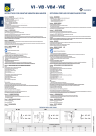
1. Remove protecting cap (44) (fig. 1).
2. Remove cotter pin (43) (fig. 2).
3. Unscrew castellated nut (42) (fig. 3).
4. Completely pull out coupling head from the bar guide (38) (fig. 4).
5. Remove tension washer (40) and rubber spring (36) from the bar guide (38).
6. Remove thrust washer (37) and rubber spring (36) from the drawbar shaft (fig. 4).
Stripping down of the coupling head
1. Detach and remove fastening parts (32 – 34 and (9) of the top cap (26) (fig. 5).
2. Disassemble locking springs (25) and coupling bolt (23) including lifting sleeve
(24) (fig. 6/7).
3. Remove wear plate (7) from the coupling mouth.
4. Detach hexagonal screws (14) at the tab washer (12) (fig. 8).
5. Remove tab washer (12) and return spring (11) (fig. 8).
6. Remove bottom guide bush (6) (fig. 9).
7. Remove coupling body (3) with the remaining fitted parts from the drawbar (1)
(fig. 10).
8. Remove top guide bush (2) (fig. 11).
Assembly of the coupling head
1. Drive in top guide bush (2) to the drawbar (1) (fig. 11).
2. Fit coupling body (3) on to the drawbar (1) (fig. 10).
3. Grease bottom guide bush (6) and drive through coupling mouth into the draw
bar. (The threaded holes of the bottom guide bush must be transverse to the
longitudinal axis of the coupling) (fig. 9).
4. Insert return spring (11) (fig. 8).
5. Screw on tab washer (12) (fig. 8).
6. Insert wear plate (7) in coupling mouth and screw up.
7. Insert coupling bolt (23) including lifting sleeve (24) the way that the axis of the
pin (24) is transverse to the longitudinal axis of the coupling (fig. 7).
8.
Insert locking springs (25) (fig.6).
9. Fill in new grease into the housing.
10. Refit top cap (26) and screw up (fig. 6).
11. Slip on rubber spring (36) and thrust washer (37) to the drawbar (1) (fig. 5).
12. Grease drawbar shaft.
Assembly to the vehicle:
1. Grease bearing surface of the thrust washer (37) on the bar guide (38).
2. Fit tension washer (40) without any other components of the towing device to
the bar guide (1) and fully tighten the castellated nut (42) by hand. Measure the
dimension X (see figures 1 – 4). Remove castellated nut (42) and tension washer
(40) again.
3. Fit the complete coupling head assembly to the bar guide (38) (fig. 4).
4. Slip on rubber spring (36) and tension washer (40) to the drawbar shaft.
5. Screw on castellated nut (42) and tighten according to "fitting instructions - item
8" (fig. 3).
7