1
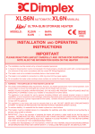
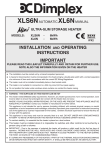
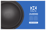
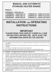
WMS(N) AUTOMATIC WMX(N) MANUAL
87570
STORAGE HEATER RANGE
MODELS:
WMX706N - 6kWh
WMS/X718N - 18kWh
WMS/X712N - 12kWh
WMS/X724N - 24kWh
INSTALLATION AND OPERATING
INSTRUCTIONS
IMPORTANT
PLEASE READ THIS LEAFLET CAREFULLY AND RETAIN FOR FURTHER USE
NOTE ALSO THE INFORMATION GIVEN ON THE HEATER
The Installation must be carried out by trained personnel.
A means for disconnection must be incorporated in the fixed wiring by a double pole switch with a
contact separation of a minimum of 3mm and in accordance with the current IEE Wiring Regulations.
The heater must not be installed immediately below a fixed socket outlet.
The heater is not suitable for connection to a 30A ring circuit.
Do not position the heater under windows where curtains can contact the heater casing.
WARNING - THE SURFACES ON THIS HEATER CAN BE HOT.
This heater meets EN60335 safety requirements. However, any heater type becomes hot in normal
operation. Care must be taken to ensure that prolonged skin contact with the heater does not occur.
WHERE YOUNG CHILDREN, INFIRM PERSONS, OR THE AGED ARE PRESENT THIS APPLIANCE
MUST BE ADEQUATELY GUARDED. Contact your installer or the manufacturer for further advice.
This appliance is not intended for use by persons (including children) with reduced physical, sensory or
mental capabilities, or lack of experience and knowledge, unless they have been given supervision for
instruction concerning use of the appliance by a person responsible for their safety. Children should be
supervised to ensure that they do not play with the appliance.
This appliance is very heavy and must be securely fixed to a wall. DO NOT UNDER ANY CIRCUMSTANCES
ATTEMPT TO MOVE OR REPOSITION THIS HEATER WITHOUT SEEKING EXPERT ADVICE.
To maintain stability, it is essential that the heater is placed on a level surface and care should be taken
to avoid irregular surfaces, such as may result from carpets or tiled surrounds partially protruding under
the heater.
This heater must be installed where it is impossible for switches and other controls to be touched by a
person using a bath or shower.
IMPORTANT - Due to the newness of materials the heater will produce a slight smell for the first few
days of operation. ROOMS MUST BE WELL VENTILATED AND YOUNG CHILDREN, CAGED BIRDS,
OR PERSONS WITH RESPIRATORY COMPLAINTS MUST NOT REMAIN IN CLOSE PROXIMITY TO
THE HEATER DURING THE FIRST 48 HOURS OF THE COMMISSIONING PERIOD.
IF, DURING ANY REASSEMBLY OF THE HEATER, A PART OF THE THERMAL INSULATION SHOWS
DAMAGE OR DETERIORATION WHICH MAY IMPAIR SAFETY, IT SHOULD BE REPLACED BY AN
IDENTICAL PART.
INSTALLATION INSTRUCTIONS
PREPARATION
The heater will arrive
separately from its
storage bricks, the
following bricks will
be required:
Model 706N - 4 bricks
Model 712N - 8 bricks
Model 718N - 12 bricks
Model 724N - 16 bricks
3. Place the heater on its feet and in the desired position
against the wall. Ensure the heater is based on a firm level
surface at least 75mm from any end wall and at least 250mm
below any shelf or similar projection. Cut away any gripper
rod or carpet which would prevent the heater sitting firmly
on the floor.
3.
4. Mark the position of the two outside corners of the wall
bracket with the heater pushed tight against the wall. Remove
the wall bracket from the heater by removing the screw at each
end. Place the heater to one side and reposition the bracket
against the wall using the corner marks for alignment.
WARNING - This appliance must be earthed
Only heat resisting cable (min. rating T85) should be
used. The wires in the mains cable will be coloured as
follows:GREEN & YELLOW EARTH
BLUE
NEUTRAL
BROWN
LIVE
SUGGESTED FIXINGS
Four fixing positions must be chosen for the 724N, three for
the 718N and two for the 712N and 706N. Mark the positions
for the fixing holes - two at the extreme ends and the others
spaced evenly between them. Remove the bracket from
the wall, drill the holes in the positions marked, and insert
suitable fixings previously described. Secure the wall bracket
to the wall.
4.
SOLID BRICK/BLOCK: No. 10 Size plastic inserts,
8mm drill bit. Drill hole 15mm deeper than plastic insert
length.
PLASTERBOARD - If possible locate studding and use
No. 10 woodscrews directly into the wood, otherwise
M5 rawlplug intersets are suitable.
NOTE: FOR OTHER WALL TYPES (eg. Timber frame
and hollow concrete) SEEK SPECIALIST ADVICE.
FIXING ASSEMBLY
1. ENSURE THAT FIXING KIT AND FEET HAVE BEEN
LOCATED BEFORE DISPOSING OF PACKAGING.
2. Fit the feet with the open end of the foot to the front of the
heater. Secure each foot using two taptite screws provided
in the fixing kit.
2.
5. If mains connection is to be made from the left side, at
this point the mains lead must be secured to the back of the
heater using ties provided in the fixing kit.
5.
6. THE FOLLOWING MUST BE APPLIED WHEN
FIXING THE HEATER TO THE WALL BRACKET
i) If no skirting board is present secure the heater through
the wall bracket slots closest to the wall.
ii) If 100mm (4in.) skirting is present secure the heater
through the outer slots.
iii) If skirting taller than 150mm (6in.) is present this must be
reduced to 150mm (6in.) over the entire width of the heater
plus 25mm (1in.) at each end.
Do not fully tighten these screws until the bricks are loaded
into the heater as some settling of the heater may occur.
NOTE: NEVER REMOVE THESE SCREWS WITHOUT
FIRST UNLOADING THE HEATER.
6.
11.
12. Fit the front layer of bricks again with the recess towards
the element. The complete core will comprise:
706N - 1 x 4 Brick Columns
712N - 2 x 4 Brick Columns
718N - 3 x 4 Brick Columns
724N - 4 x 4 Brick Columns
13. Replace the inner front complete with insulation by
locating its bottom edge behind the front lip of the chassis and
inserting retaining screws along the top and both sides.
14. For models 712N, 718N and 724N only, check that the
flap mechanism operates freely on its hinges and that with
the output control set to 1 the flap is correctly seated in its
closed position.
7. Remove the front panel by removing the two self tapping
screws along its bottom edge. With hands positioned on each
side of the panel, lift upwards to unhook the top edge whilst
pressing down on the top panel with your thumbs. The panel
can now be lifted clear and set to one side.
7.
15. Feed the mains cable through the cable clamp and
make connections as marked on heater. Pull back any
slack through the clamp and tighten clamping screw. Make
sure clamp is tightening on outer sheath of cable and not on
individual conductors.
WARNING - This appliance must be earthed
15.
8. Remove the inner front by removing the screws along its
top and sides. As the front insulation is attached care must be
taken when lifting this panel from the heater and placing it to
one side. Remove the internal packing by sliding it up and off
the elements taking care not to damage the insulation.
8.
9.
ENSURE THAT CABLE CLAMP
IS SECURELY ATTACHED TO
THE CHASSIS OF THE HEATER
16. Replace outer front panel and grille by hooking the grille
into its retaining slot on the top panel and lowering it into
position. Secure the front panel with the two self tapping
screws.
9. Remove one element to allow access for the back rows of
bricks. On the 724N remove the element to the right of centre,
on the 718N remove the central element, on the 712N the left
hand element should be removed and, on the 706N, there is
only one element.
Loosen the two screws securing the element tails in the ceramic
connector block, and lift the element up and out of the heater.
10. Carefully fit the bottom row of the back layer of bricks
placing the two end bricks in position first with the recess
towards the element. Fit the top row of bricks also with the
recess towards the element.
11. Refit the element which has been removed by feeding the
tails down through the hole in the base insulation and into the
connector block. Ensure the element is fully pushed home
then securely tighten the two screws in the block.
16.
17. Check that the screws securing the heater to the wall
bracket have been fully tightened.
IT IS ESSENTIAL THAT ALL SCREWS ARE REPLACED
TO ENSURE EARTH CONTINUITY.
Once installed do not attempt to reposition the heater without
first obtaining the services of a competent electrician.
OPERATING INSTRUCTIONS
OPERATION
This storage heater takes in Energy
when electricity tariffs are low and
dissipates it when tariffs are normal.
SAFETY INSTRUCTIONS
1. Ventilate rooms well during commissioning
2. Do not move the heater in any way once installed without
the services of a competent electrician.
3. Do not cover the heater with clothing etc. at any time or
position furniture close to or against the heater.
4. Ensure a clearance of at least 150mm between heaters and
curtains.
5. Floor standing heaters must only be fitted with the back
against a wall.
6. Should your heater fail to operate either employ the services
of a competent electrician or Telephone (0845) 600 5111.
ALSO REFER TO COVER PAGE
COMMISSIONING
Set both the Input Control and the Output Control to 6 and
leave the heater for 48 hours.
Following the commissioning period adjust the controls as
stated below.
SETTING THE CONTROLS
The controls are located under the hinged flap at the top right hand
corner of the heater.
To adjust the controls on the heater use a coin and engage it in the
slots provided on the top surface of the knob. There are no user
adjustable controls on the WMX706N.
CONTROL FUNCTIONS
THE INPUT CONTROL
For models WMS712N, 718N, 724N only:
This heater is fitted with a user adjustable automatic input control
which varies the charge taken in response to weather conditions taking
into account the amount of energy already stored in the heater.
Set at 6 the heater takes maximum charge and at 1 the heater
takes a minimum charge at any room temperature. The casing of
the heater, particularly in late evening, may feel cool, this is quite
normal. The input control may require a few days experimentation
before your comfort level is established.
Initially set the control to 3, the following evening if the room is too warm
reduce to 2 or if it is too cool increase to 4. On subsequent evenings
adjust by half divisions until your comfort level is achieved.
Having established the setting the input will automatically carry the
amount of heat stored to compensate for weather variations.
For models WMX712N, 718N, 724N only:
Initially set the input to 4. If the heater does not maintain a satisfactory
room temperature the following day this setting should be increased.
Conversely if the room temperature is too high this setting should
be reduced.
The input control should only require seasonal adjustments.
THE OUTPUT CONTROL
For all models except WMX706N
Most of the stored heat is radiated from the casing during the
discharge period. However, some of the heat is emitted through the
grille at the top of the heater and this additional heat (or boost) is
regulated by the Output Control.
With this set to 6 the boost begins in the early afternoon. Turning the
control towards 1 will progressively delay the commencement of the
boost. At 3 the boost will start in the evening. Once set, the boost
will repeat itself automatically day after day.
If no boost is required e.g. when the room will be unoccupied for a long
period, set the Output Control to 1. With the control in this position,
the heater will take less energy during the next charging up period.
CLEANING
To maintain the appearance of the heater wipe occasionally with a
dry cloth when the heater is cool.
Do not use abrasive powders of furniture polish.
Discolouration of wall finishes can sometimes occur immediately
above a storage heater due to the properties of some paints and
decorating materials or the presence of environmental impurities
in the air (such as soot or incense generated from the burning of
candles etc.).
AFTER SALES SERVICE
Your storage heater is guaranteed for two years from date of
purchase. We undertake to repair or exchange within the period,
any part found to be defective due to a manufacturing fault. This
guarantee does not affect your statutory rights.
Should you require after sales service, please contact the supplier
through whom you purchased the heater, or telephone 0845 600
5111.
Please do not initially return faulty appliance, or part of an appliance
to us as this may result in transit damage and/or a delay in providing
service.
Let us know your difficulty quoting the model number and serial
number (located along the wall bracket). We will then take the
appropriate action.
RECYCLING
For electrical products sold within the European
Community. At the end of the electrical products useful
life it should not be disposed of with household waste.
Please recycle where facilities exist. Check with your
Local Authority or retailer for recycling advice in your country.
Derby Products Pty. Ltd
ABN 81 009 477 561
P.O. Box 84, Glenorchy
Tasmania 7010
Tel: 1800 030 668
e-mail: [email protected]
#Web address: www.derbyproducts.com.au
This product complies with the European Safety Standards EN60335-2-30 and the European Standard
Electromagnetic Compatibility (EMC) EN55014, EN60555-2 and EN60555-3.
These cover the essential requirements of EEC Directives 2006/95/EC and 2004/108/EC
© GDC Group Ltd. All rights reserved. Material contained in this publication may not be reproduced in whole or in part,
without prior permission in writing.
A division of the GDC Group Ltd, Millbrook House, Grange Drive, Hedge End, Southampton SO30 2DF
Part No. 87570
Issue 2