1
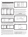
XLS6N AUTOMATIC XL6N MANUAL
ULTRA-SLIM STORAGE HEATER
MODELS:
XLS6N
XL6N
-
6kWh
6kWh
IPX2
INSTALLATION AND OPERATING
INSTRUCTIONS
IMPORTANT
PLEASE READ THIS LEAFLET CAREFULLY AND RETAIN FOR FURTHER USE.
NOTE ALSO THE INFORMATION GIVEN ON THE HEATER
The installation must be carried out by a trained competent personnel.
A means for disconnection must be incorporated in the fixed wiring by a double pole switch with a contact separation
of a minimum of 3mm and in accordance with the current IEE Wiring Regulations
The heater must not be installed immediately below a fixed socket outlet.
The heater is not suitable for connection to a 30A ring circuit (24 hour peak supply).
Do not position the heater under windows where curtains can contact the heater casing.
WARNING - THE SURFACES ON THIS HEATER CAN BE HOT
This heater meets EN60335 safety requirements. However, any heater type becomes hot in normal operation. Care
must be taken to ensure that prolonged skin contact with the heater does not occur.
WHERE YOUNG CHILDREN, INFIRM PERSONS, OR THE AGED ARE PRESENT THIS APPLIANCE MUST BE
ADEQUATELY GUARDED. Contact your installer or manufacturer for further advice.
This appliance is not intended for use by persons (including children) with reduced physical, sensory or mental
capabilities, or lack of experience and knowledge, unless they have been given supervision for instruction concerning
use of the appliance by a person responsible for their safety. Children should be supervised to ensure that they do
not play with the appliance.
This appliance is very heavy and must be securely fixed to a wall. DO NOT UNDER ANY CIRCUMSTANCES
ATTEMPT TO MOVE OR REPOSITION THIS HEATER WITHOUT SEEKING EXPERT ADVICE.
To maintain stability, it is essential that the heater is placed on a level surface.
This heater must be installed where it is impossible for switches and other controls to be touched by a
person using a bath or shower.
IMPORTANT - Due to the newness of materials the heater will produce a slight smell for the first few days of
operation. ROOMS MUST BE WELL VENTILATED AND YOUNG CHILDREN, CAGED BIRDS, OR PERSONS
WITH RESPIRATORY COMPLAINTS MUST NOT REMAIN IN CLOSE PROXIMITY TO THE HEATER DURING
THE FIRST 48 HOURS OF THE COMMISSIONING PERIOD.
IF, DURING ANY REASSEMBLY OF THE HEATER, A PART OF THE THERMAL INSULATION SHOWS DAMAGE
OR DETERIORATION WHICH MAY IMPAIR SAFETY, IT SHOULD BE REPLACED BY AN IDENTICAL PART.
INSTALLATION INSTRUCTIONS
PREPARATION
The heater will arrive separately from its
storage bricks, 4 bricks will be required.
(2 Packs) Catalogue No. XT8300
MODEL ONLY - The Room Sensor is located at the
3. XLS6N
rear of the right hand side of the heater. Remove sensor
from plate, carefully slide the sensor plate down from its transit
position to its operational position. Refit sensor to plate.
3.
the heater on its feet and in the desired position
4. Place
against the wall. Ensure the heater is based on a firm
level surface at least 75mm from any end wall and at least
250mm below any shelf or similar projection. Cut away any
gripper rod or carpet which would prevent the heater sitting
firmly on the floor.
4.
WARNING - This appliance must be earthed
Only heat resisting cable (min. rating T85) should be
used. The wires in the mains cable will be coloured as
follows:GREEN & YELLOW EARTH
BLUE
NEUTRAL
BROWN
LIVE
SUGGESTED FIXINGS
SOLID BRICK/BLOCK: No. 10 Size plastic inserts,
8mm drill bit. Drill hole 15mm deeper than rawlplug
length.
PLASTERBOARD - If possible locate studding and use
No. 10 woodscrews directly into the wood, otherwise
M5 rawlplug intersets are suitable.
the position of the two outside corners of the wall
5. Mark
bracket with the heater pushed tight against the wall.
Remove the wall bracket from the heater by removing
the screw at each end. Place the heater to one side and
reposition the bracket against the wall using the corner marks
for alignment.
Four fixing positions must be chosen for this heater. Mark the
positions for the fixing holes - one at each end. Remove the
bracket from the wall, drill the holes in the positions marked,
and insert suitable fixings previously described. Secure the
wall bracket to the wall.
5.
NOTE: FOR OTHER WALL TYPES (e.g. Timber frame
and hollow concrete) SEEK SPECIALIST ADVICE.
FIXING ASSEMBLY
1.
ENSURE THAT FIXING KIT AND FEET HAVE BEEN
LOCATED BEFORE DISPOSING OF PACKAGING.
Fit the feet with the open end of the foot to the front of
the heater. Secure each foot using two taptite screws
provided in the fixing kit.
2.
2.
connection is to be made from the left side, at
6. Ifthismains
point the mains lead must be secured to the back of
the heater using ties provided in the fixing kit.
6.
7. THE FOLLOWING MUST BE APPLIED WHEN 12.
FIXING THE HEATER TO THE WALL BRACKET
i) If no skirting board is present secure the heater through
the wall bracket slots closest to the wall.
ii) If 100mm (4in.) skirting is present secure the heater
through the outer slots.
iii) If skirting taller than 150mm (6in.) is present this must be
reduced to 150mm (6in.) over the entire width of the heater
plus 25mm (1in.) at each end.
Do not fully tighten these screws until the bricks are loaded
into the heater as some settling of the heater may occur.
NOTE: NEVER REMOVE THESE SCREWS WITHOUT
FIRST UNLOADING THE HEATER.
7.
the front bricks again with the recess towards the
13. Fit
element.
14.
Replace the inner front complete with insulation by
locating its bottom edge behind the front lip of the
chassis and inserting retaining screws along both sides.
the mains cable through the cable clamp and
15. Feed
make connections as marked on heater. Pull back any
slack through the clamp and tighten clamping screw.
Remove the front panel by removing the two self tapping
8.
screws along its bottom edge. With hands positioned on
each side of the panel, lift upwards to unhook the top edge
whilst pressing down on the top panel with your thumbs. The
panel can now be lifted clear and set to one side. Discard
the packing which had been sandwiched between the inner
front and outer front.
WARNING
This appliance must be earthed
15.
8.
Replace outer front panel and grille by hooking the grille
the inner front by removing the screws along its 16.
into its retaining slot on the top panel and lowering it
9. Remove
sides. As the front insulation is attached care must be
taken when lifting this panel from the heater and placing it to
one side. Remove the internal packing by sliding it up and
off the elements taking care not to damage the insulation.
9.
10.
into position. Secure the front panel with the two self tapping
screws.
16.
the element to allow access for the back rows
10. Remove
of bricks.
Loosen the two screws securing the element tails in the ceramic
connector block, and lift the element up and out of the heater.
Carefully fit the bottom rear brick with the narrow end of
the recess over the slot in the base insulation. Fit the
top rear brick with the narrow end of the recess to the top.
11.
t the element which had been removed by feeding
12. Refi
the tails down through the hole in the base insulation
and into the connector block. Ensure the element is fully
pushed home then securely tighten the two screws in the
block.
that the screws securing the heater to the wall
17. Check
bracket have been fully tightened.
IT IS ESSENTIAL THAT ALL SCREWS ARE REPLACED
TO ENSURE EARTH CONTINUITY.
Once installed do not attempt to reposition the heater without
first obtaining the services of a competent electrician.
Thermal overload protection
This appliance is protected by a
thermal safety cutout which will
operate to isolate the electricity
supply if, for example, the heater
surfaces or grille are obstructed to
cause overheating.
The cutout should not operate if the
instructions given in this leaflet and
clearances regarding positioning are
strictly followed.
However, if the cutout has operated
before following the instructions
below determine the cause of the
cutout operating. If the heater has
not obviously or inadvertently been
misused - e.g. covered - it will be
necessary to have the appliance
fully checked by a Dimplex Service
Agent. (A list of Dimplex Service Agents
is enclosed in the leaflet envelope and
should be retained by the user).
OPERATING INSTRUCTIONS
SAFETY INSTRUCTIONS
1. Ventilate rooms well during commissioning
2. Do not move the heater in any way once installed without
the services of a competent electrician.
3. Do not cover the heater with clothing etc. at any time or
position furniture close to or against the heater.
4. Ensure a clearance of at least 150mm between heaters and
curtains.
ALSO REFER TO COVER PAGE
AUTOMATIC OPERATION
Dimplex XL6N and XLS6N Storage Heaters store heat overnight
using cheap off peak electricity and discharge this heat the following
day. The XL6N is preset at the factory to always take a full charge.
XLS6N models are fitted with an external sensor which measures
room temperature and adjusts the input to the heater automatically,
thus ensuring the most effective use of electricity. These operating
instructions assume that the correct size of storage heaters have
AFTER SALES SERVICE
Your product is guaranteed for two years from the date of
purchase.
Within this period, we undertake to repair or exchange this product
free of charge (subject to availability) provided it has been installed
and operated in accordance with these instructions.
Your rights under this guarantee are additional to your statutory rights,
which in turn are not affected by this guarantee.
Should you require after sales information or assistance with this
product please go to www.dimplex.co.uk where you will find our
self help guide by clicking on “After Sales” or ring our help desk on
0845 600 5111 (UK) or 01 842 4833 (ROI). It would assist us if you
can quote the model number, series, date of purchase, and nature
of the fault at the time of your call. The customer services help
desk will also be able to advise you should you need to purchase
any spares.
Spare parts are aslo available on the website www.dimplex.
co.uk.
Please do not return a faulty product to us in the first instance as
this may result in loss or damage and delay in providing you with
a satisfactory service.
Please retain your receipt as proof of purchase.
been selected to cater for the heating requirements of the room.
CLEANING
To maintain the appearance of the heater wipe occasionally with a
dry cloth when the heater is cool.
Do not use abrasive powders of furniture polish.
RECYCLING
For electrical products sold within the European
Community. At the end of the electrical products useful
life it should not be disposed of with household waste.
Please recycle where facilities exist. Check with your
Local Authority or retailer for recycling advice in your country.
This appliance complies with the European Standards EN60335-2-30, EN 60 335-1, EN 60 335-2-61, EN 61000-3-2,
EN 61000-3-3, EN 55014 and EN55104 for Safety & Electromagnetic Compatibility.
These standards cover the requirements of the EMC Directives 89/336 & 73/23.
Dimplex (UK) Ltd
Millbrook House
Grange Drive
Hedge End
Southampton
Hampshire
SO30 2DF
83708 Issue 7 : June 2008
Customer Help Line
0845 600 5111
Mon–Thurs 08.30-17.00 and Fri 08.30-16.00 (Sept-April)
Mon–Thurs 08.30-17.00 and Fri 08.30-15.00 (May to August)
Fax
01489 773 050
Web-site
www.dimplex.co.uk
e-mail
[email protected]
Republic of Ireland
01 842 4833
© Dimplex UK Limited
All rights reserved. Material contained in this publication may not be reproduced in whole or part, without prior permission in writing from Dimplex UK Limited.