1
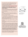
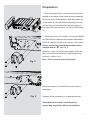
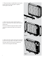
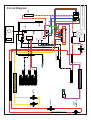
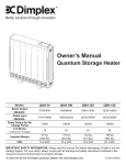
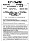
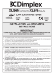
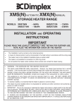
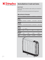
Installation Instructions
A world of expertise
IMPORTANT
These instructions should be read carefully and retained for
future use.
Note also the information presented on the appliance.
Quantum Heater
Models:
QM070
QM100
QM125
QM150
792/880W
1017/1130W
1242/1380W
Storage
Output
230/240V~: 1435/1560W 2042/2220W 2540/2760W
3024/3300W
Boost
Output
230/240V~: 567/630W
11115-2
-1-
Rated
Charge
Period:
7.7 - 7 Hours
Bricks:
18
24
30
36
Installed
Weight:
91kg
115kg
142kg
165kg
kWh:
10.9kWh
15.4kWh
19.3kWh
23.1kWh
IMPORTANT
WARNING - THE SURFACE OF THIS HEATER CAN
BE HOT.
WARNING - THIS APPLIANCE MUST BE EARTHED.
IMPORTANT
These instructions should
be read carefully and
retained for future use.
Note also the information
presented on the
appliance.
• The installation must be carried out by a suitably qualified
individual in accordance with the latest IEE Regulations for
electrical equipment.
• For each supply, a means for disconnection must be incorporated
in the fixed wiring by a double pole switch with a contact
separation of a minimum of 3mm and in accordance with the
current IEE Wiring Regulations.
• The heater must not be installed immediately below a fixed socket
outlet.
• The supply to the storage elements is not suitable for connection
to a 30A ring circuit (24 hour peak supply).
• If a supply cord is damaged, it must be replaced by a qualified
individual in order to avoid a hazard.
• The surface temperatures of this heater are within the
requirements of EN60335-2-61, the European Standard covering
the safety requirements for Electric Storage Heaters, and
momentary contact with any part of the heater should not cause
injury. However, in order to be effective, heaters of any type do
get hot, especially around the air outlet grille.
• This appliance can be used by children aged from 8 years and
above and persons with reduced physical, sensory or mental
capabilities or lack of experience and knowledge if they have
been given supervision or instruction concerning use of the
appliance in a safe way and understand the hazards involved.
• Children shall not play with the appliance. Cleaning and
user maintenance must not be made by children without
supervision.
• Children of less than 3 years should be kept away unless
continuously supervised. Children aged from 3 years and less
than 8 years can only switch on/off the appliance provided
that it has been placed or installed in its intended normal
operating position and they have been given supervision or
instruction concerning use of the appliance in a safe way and
understand the hazards involved. Children aged from 3 years
and less than 8 years must not plug in, regulate and clean the
appliance or perform user maintenance.
CAUTION — Some parts of this product can become very
hot and cause burns. Particular attention has to be given
where children and vulnerable people are present.
• If aged or infirm persons, or young children, are likely to be left
unsupervised in the vicinity of a heater precautions should be
taken to ensure that prolonged contact with the heater cannot
occur.
-2-
We recommend that a guard is fitted around the heater, as
is normal with some types of heating appliances in similar
circumstances. A range of guards specially designed for
Dimplex storage heaters is available.
If you require further information on these guards, please see
contact details on back page of the Operating Instructions.
CAUTION: DO NOT COVER SURFACES OF THE
HEATER AND DO NOT OBSTRUCT THE AIR
OUTLET GRILLE.
• Surfaces of the heater should not be covered or obstructed as
this can cause excessive temperatures that can be hazardous
and may cause safety cut-outs to operate. This will stop the
heater from working.
• Do not put clothes, fabrics or any combustible materials on the
heater.
• Do not position the heater where objects such as curtains can
come to within 75mm (3”) of the top and ends of the heater casing.
• Do not sit or stand on the heater.
• Do not place objects in contact with the heater.
• To maintain stability, it is essential that the heater is placed
on a level surface and care should be taken to avoid irregular
surfaces, such as may result from carpets or tiled surrounds
partially protruding under the heater.
• Choose appropriate fixings to securely attach the heater to
the wall, see section titled ‘Installing the heater’ for detailed
information.
• This heater must be installed where it is impossible for its
switches and other controls to be touched by a person using a
bath or shower.
• IMPORTANT - Due to the newness of materials the heater will
produce a smell for the first few days of operation. For installation
with multiple new heaters the commissioning should be staggered
over a few days (two charge periods for each heater - normally
48 hours) to minimise the odour levels. Rooms must be well
ventilated and young children, caged birds, or persons with
respiratory complaints must not remain in close proximity to the
heater during the first 48 hours of the commissioning period.
PLEASE NOTE: THIS STORAGE HEATER IS VERY HEAVY
AND MUST BE SECURELY FIXED TO A SOUND WALL.
• If, during any reassembly of the heater, a part of the thermal
insulation shows damaged or deterioration which may impair
safety, it should be replaced with an identical part.
• Quantum heaters are not suitable for installation in bathrooms,
shower rooms etc. or in areas of high humidity.
-3-
Do not place objects within
300mm of the front of the
heater and 150mm (min.
75mm) either side.
ATTENTION:
IN ORDER TO AVOID
OVERHEATING DO NOT
COVER THE HEATER
Preparation
1. Place the heater flat on the ground with arrows
printed on the base of the carton pointing upwards.
Fig. 1
Open the carton at the bottom, slide the heater out
of the carton by at least 200mm exposing the feet
and the fixing kit located within the packaging on
the right hand side. Remove the feet and the fixing
kit.
2. Secure the feet to the heater. For models QM070
and QM100 two locations are possible indicated by
X and Y markings visible on the base of the heater.
Y
X
Y
X
Ensure the feet are fixed at the location holes
marked with an ‘X’, see Fig. 2.
However, if this is a replacement heater check the
pitch of the feet and choose the appropiate fixing
positions - either X or Y.
Note - Foot screws are in the fixing kit.
Fig. 2
X
YX
Y
Stand the heater on its feet before removing the
packaging.
Fig. 2
Dispose of the packaging in an appropriate way.
Read these instructions carefully before
proceeding any further with the installation.
-4-
3. Ensure the heater is stable before removing the
screws which hold the grille panel in position.
Set the grille to one side.
Fig. 3
4. Remove the two screws located towards to
bottom of either end of the heater, which retain the
heater sides.
Push the left hand and right hand sides vertically
upwards to release each side from its securing
points.
Fig. 4
5. Remove the two screws securing the front panel,
located at the upper sides of the heater, and swing
the upper edge of the front panel forwards and
unhook it from along the heater base.
Fig. 5
-5-
Installing the Heater
The heater must be securely fixed to a wall. Screws
with suitable wall fixings for solid walls are provided.
If other walls types are encountered it is the installer
who must choose the most suitable fixing.
SUGGESTED FIXINGS
SOLID BRICK/BLOCK: No. 10 size plastic inserts,
8mm drill bit. Drill hole 15mm deeper than plastic
insert length.
PLASTERBOARD - If possible locate studding and
use No. 10 woodscrews directly into the wood,
otherwise M5 rawlplug intersets are suitable.
NOTE: FOR OTHER WALL TYPES (eg. timber
frame and hollow concrete) SEEK SPECIALIST
ADVICE.
If the floor is carpeted then the carpet should be slit
and underlay cut away to allow the feet to rest firmly
on the floor. Carpet gripper must be locally removed
so that the feet may rest in a level position.
This appliance is heavy. The floor must be checked
to ensure that it is capable of bearing the weight of
the unit, up to 165kg.
DO NOT UNDER ANY CIRCUMSTANCES
ATTEMPT TO MOVE OR REPOSITION THIS
HEATER WITHOUT SEEKING EXPERT ADVICE.
-6-
6. Place the heater in its final position and mark
the fixing holes through the location holes visible
through the back of the heater.
Mark the fixing positions at the two extreme ends of the
heater with the heater pushed tight against the wall.
Remove the wall bracket from the heater by removing
the two screws at each end of the bracket. Place
the heater to one side and reposition the bracket
against the wall aligning it with the location marks. It is
advisable to use a screwdriver with a magnetic tip
as screws dropped may enter the fan housing.
Fig. 6
7. Six fixing positions must be selected for each
model. Mark the positions for the fixing holes.
Remove the bracket from the wall, drill the holes
and fit the wall fixings best suited to the application.
QM070
Secure the wall bracket to the wall using six screws.
QM100
Secure the heater using the appropriate screw fittings.
NOTE: UNDER NO CIRCUMSTANCES SHOULD
THESE SCREWS BE REMOVED WITHOUT FIRST
REMOVING ALL BRICKS FROM THE HEATER.
x
x
x
x
Fig. 7
x
x
x
x
x
x
x
x
QM125
x
x
x
x
x
x
QM150
x
x
-7-
x
x
x
x
Warning: Before obtaining access
Electrical Connections
to terminals, all supply circuits
must be disconnected.
Two Mains Supplies
8. The heater leaves the factory configured
to operate with two mains supplies, a 24 hour
supply and an off peak switched supply.
Storage / Fan circuit
Ensure the brown wire is connected to the terminal
marked L.
L
N
OFF PEAK
Fig. 8
L
N
PEAK 24
HOURS
EARTH
(BOTH
SUPPLIES)
Ensure the blue wire is connected to the terminal
marked N.
The earth wire should be connected to the terminal
block marked E or
.
-8-
9. The mains cable entry bushes and terminal
blocks will be visible on the right hand side of the
unit.
Insert the mains cables through the cable gland at
the bottom of the heater in readiness for connection.
IMPORTANT - Only heat resistant ordinary
polyvinyl chloride sheathed flexible cord
should be used, the following codes apply;
IEC - 60227 IEC57 or
CENELEC - H05V2V2-F
Fig. 9
Mains Cable
If the supply cord becomes damaged, it must
be replaced by a suitably qualified individual
in order to avoid a hazard.
-9-
Building the Heater Core
10. Remove the inner front to gain access to the
core of the heater.
Lay the inner front carefully to one side to ensure it
is not damaged.
Fig. 10
11. Remove the internal packaging.
Fig. 11
- 10 -
Bricks
The bricks are supplied separately to the heater in
packs of three.
The reference number is 047243.
12. The bricks have several grooves on one
surface for locating around the elements. The two
slots through the centre of the brick create the air
passages within the core.
Position the first brick of the bottom row to the right,
firmly pressed against the side insulation with the
element grooves facing upwards and fitting neatly
around the element. Angle the element upward to fit
the brick.
Fig. 12
DO NOT DISCONNECT THE ELEMENT
TERMINALS
In addition ensure the slots for the air passages line
up with the holes in the base insulation.
Fit the remaining bricks to the bottom row, being
careful not to damage or dislodge the element.
Note - The bends in the element locate around
the grooves in the brick to secure the element.
13. Position the second row of bricks on top of
the first but this time the bricks must be upside
down ensuring the grooves are positioned over the
elements.
Fig. 13
- 11 -
14. The third row of brick is positioned in a manner
similar to the first row. Again be careful not to
damage or dislodge the element.
Fig. 14
15. Fit the forth row of brick above the third row in
the upside position.
Repeat for the fifth and sixth rows of brick built
around the third element to complete the core build.
Fig. 15
16. Remember the top row of brick must be fitted
upside down.
Check that all the bricks are secure and evenly
located.
Fig. 16
- 12 -
17. Close the core by refitting the inner front panel
complete with insulation.
Ensure the bottom edge is located inside the
chassis and that the screws are tightly secured
down each edge.
Fig. 17
IMPORTANT
Double check all mains connections are secure and
excess cable is restrained and not in contact with
any of the heater casing.
ON NO ACCOUNT SHOULD ANY SURPLUS
CABLE BE PUSHED INSIDE OR BEHIND THE
HEATER.
Once installed DO NOT attempt to reposition the
heater without first unloading the bricks.
Reassembly
To replace all the panels of the outer casing reverse
steps 3 - 5 of these instructions under the section
headed Preparation.
Ensure all fixings are secure.
- 13 -
IMPORTANT
During the initial operation some odour may be
noticed due to the newness of materials used in
manufacture. This is normal and will disappear after
a short period of use. It is however advisable to
keep the room well ventilated.
Clean the outlet grill and adjacent surfaces after the
first operation as some dust may be produced when
the heater is first used.
1
Child Lock
1
In cases where unauthorised persons may tamper
with the control settings it is possible to set a
tamper-proof feature at the time of installation,
by pressing and holding the Back button and the
Selector Dial simultaneously for three seconds,
‘Child Lock’ will apprear on the screen, repeat to
reverse. See the Operating Instructions for further
details.
Information
For cleaning, heater guards or other sales service
and Dimplex contact details please refer to the
Operating instructions.
- 14 -
- 15 -
LOWER
LEFT
THERMOSTAT
SIDE
THERMOSTAT
LEFT
CUT OUT
LIMIT
THERMOSTAT
BOOST ELEMENT
STORAGE ELEMENTS
AIR SENSOR
CORE THERMISTOR
DFB
RIGHT THERMOSTAT
SFB
1
No. 1
No. 2
3
4
5
NEUTRAL EARTH LIVE
BI-METAL
NEUTRAL
PCB
WHITE
CORE
FAN
NEUTRAL LIVE NEUTRAL LIVE
2
FAN
NEUTRAL
BOOST
NEUTRAL
LIVE
RED
FAN
ELEMENT
NEUTRAL
No. 3
ELEMENT
NEUTRAL
BLACK
ROOM
EARTH
ACL
ACN
INDICATES WHITE WIRE
ROOM
THERMISTOR
USER
INTERFACE
USER INTERFACE
INDICATES ORANGE WIRE
FILTER
L
N
FAN
RESISTOR
Circuit Diagram
- 16 -