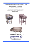
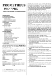
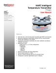
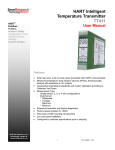
1
CORONA OPERATING INSTRUCTIONS AND CAUTIONS
Q U ES TIO NS ?
After reading this manual if there is anything that you are unsure of or if you need service email
[email protected] and be sure to include your model number and serial number in the email.
Address : L&L Kiln Mfg., Inc. 505 Sharptown Road, Swedesboro NJ 08085
Web: hotkilns.com
Phone: 856-294-0077
Fax: 856-294-0070
Hours: Mon-Fri 8:30-5:00 (Eastern Standard Time)
B A S IC O P ER A TIO N
•
•
These kilns are designed to plug into 120 volt, 15 amp circuits.
Once you plug the kiln in and turn on the switch then you can follow the Orton Instructions for
programming and using the control.
•
Be sure to read the safety instructions in this manual to make sure you are operating in a safe manner
to avoid any injuries or property damage.
•
DO NOT FIRE THE KILN UNATTENDED
A P P LIC A TIO NS
•
•
•
This kiln is designed for metal clay firing (including PMC and Art Clay), glass slumping, glass
annealing, enameling, some metal heat treating, low-fire ceramics and many other jobs that require
heating non-combustible materials up to 2012°F.
Do not use for firing anything that might be combustible or that might expand explosively when firing.
The very sophisticated Orton program control has three kinds of programs: PMC programs, Art Clay
programs and 12 completely programmable custom programs with 8 segments in each program. Each
segment is defined by a ramp, a set-point temperature, and a hold time. See the separate Orton instruction
manual for detail on how to use the control.
S P EC IFIC A TIO NS
•
Model Number: CN868
•
Temperature Rating: 1100°C, 2012°F
•
Inside Dimensions: 7-3/4” (19.7 cm) wide by 8-1/4” (20.9 cm) deep by 5-3/4” (14.6 cm) high
•
Outside Dimensions: 13” (33 cm) Wide by 14” (35.6 cm) Deep by 14-3/4” (37.5 cm) High
•
Kiln Weight: 30 lbs (13.6 Kg)
•
Electrical Specifications: 12 amps, 120 volts, 1440 watts
•
Power Cord/Plug: 6 foot cord with a 15 amp 5-15P plug
•
Vent: 0.5” (1.3 cm) vent hole in top.
•
Fuse: ½ amp control circuit fuse
•
Insulation: 1-1/2” (3.8 cm) molded ceramic fiber with a 3/4” (1.9 cm) air space between the case
and the insulation module.
•
Elements: Two elements, one on each side. Elements are molded into the machined ceramic fiber
insulation module.
Page 1 Rev:11-18-11
CORONA OPERATING INSTRUCTIONS AND CAUTIONS
•
Control: Control: Orton Autofire Express with five PMC (Precious Metal Clay) programs, three
ACS (Art Clay) programs and twelve custom programs each with eight segments. Each program has
eight segments with a ramp, soak, and set point for each segment.
•
Thermocouple: Type K 14 gauge located in the center back.
•
Warranty: One year limited warranty.
S A FETY INS TR U C TIO NS
SAFETY NOTICE
•
All recommended cautions and requirements are meant to assist Users to properly and safely operate their
kilns. Many of these cautions apply to kilns generally, as well as to metal clays, glass fusing, and ceramic
processes in general, regardless of brand or design.
•
Kilns operate at high temperatures and make use of high voltages/amperages. If improperly installed,
maintained, or used a kiln can cause serious personal injury or property damages.
•
Kilns are provided with various safety, performance, and operating limits, designs and devices which, if
disconnected, altered, tampered with, or changed by User, User's employees, User's agents, or others
acting on User's behalf or with User's knowledge, will become User's sole risk and responsibility.
•
User also has the sole responsibility for assigning kiln operation to properly trained adults who have
demonstrated common sense and a general aptitude for such work and who have read and understood the
kiln operating/maintenance instructions and this notice.
•
It is User’s sole responsibility to understand and assure adherence to all safety notices and installation,
operating, and maintenance instructions provided by this notice, the applicable web site and/or by the
kiln manufacturer.
IMPORTANT: READ THIS ENTIRE GUIDE IN ITS ENTIRERTY BEFORE INSTALLING OR
OPERATING YOUR KILN
INSTALLATION
USE A PROPERLY SIZED ELECTRICAL CIRCUIT
•
An improperly sized or installed circuit may cause a fire or personal injury.
•
Most of these kilns operate on 120 volts under 15 amps. They will work on the typical USA 120 volt, 15
amp circuit. However, do not operate any other electrical appliances on the same circuit. Look at the data
nameplate on your kiln to be sure of the amperage rating.
CLEARANCES AND FLAMMABLE SURFACES
•
•
•
•
Install kiln so that the hot surface of the kiln is no closer than 12" (30 cm) to any wall. Keep it 48” (122
cm) clear above.
Avoid installing your kiln in a small enclosed space, such as a closet, as this can increase fire danger.
The essential issue with kiln clearance is to keep excessive heat from flammable surfaces. Remember, even
when you follow clearance and ventilation recommendations, the kiln is giving off heat. Do not locate
the kiln near materials or surfaces that can be affected by elevated temperatures.
If you operate the kiln on a surface that may burn or discolor with heat then use some sort of insulation
between the kiln and the surface and check to make sure it is not overheating.
CHECK TEMPERATURES AROUND KILN
Check temperatures around the kiln when it is at maximum temperature to be sure that you are not
Page 2 Rev:11-18-11
CORONA OPERATING INSTRUCTIONS AND CAUTIONS
creating an unsafe condition.
LEVELING THE KILN
Operate the kiln on a level surface and be sure it does not wobble.
THERMOCOUPLE
•
•
Thermocouple must be inserted into the kiln at least 1" (2.5 cm) in from the inside surface of the kiln
chamber. If the measuring tip of a thermocouple is buried inside the insulation, the thermocouple will
measure a lower temperature than the actual temperature in the kiln. This could cause an overfire of the
kiln.
Replace thermocouple once it is no longer reasonably accurate or if the tip appears to be severely corroded.
DON'T USE AN EXTENSION CORD
Never use an extension cord with your kiln. Locate the kiln close enough to an outlet to plug it directly
into the outlet using only the kiln's supplied power cord.
KEEP KILN DRY & IN PROTECTED SPACE
The kiln must be kept dry. Water in contact with a kiln can cause an electrocution hazard.
KEEP A FIRE EXTINGUISHER NEAR KILN
•
•
Keep an adequate fire extinguisher near the kiln and check it on a regular basis.
Use a fire extinguisher that is rated for electrical fires (we recommend ABC rating).
OPERATING ENVIRONMENT
VENTILATION IS ESSENTIAL
•
•
Kilns may generate harmful fumes when firing some materials.
Install kiln in well-ventilated area. Never operate in any enclosed space unless you have good ventilation.
•
Ventilation is also critical to preventing heat buildup, which can present a significant fire hazard in an
enclosed space.
AMBIENT TEMPERATURES
The kiln should be operated in an environment that is between -18°C (0°F) and 38°C (100°F).
KEEP CHILDREN & ANIMALS AWAY FROM KILN
•
•
Do not operate kiln near any children, animals, and unqualified adults (anyone who is not able to
understand these cautions) that may be in the area of the kiln.
When not in use, secure your kiln from all animals, children, and unqualified adults. This is especially
important in a schoolroom setting, where children might not follow safety precautions and procedures.
KEEP FLAMMABLES AWAY FROM KILN
Do not put sealed containers or combustible materials such as solvents, paper, or rags, in or near kiln; an
explosion or fire could result.
TRIPPING HAZARDS
•
•
Be sure to remove tripping hazards near the kiln.
Keep the kiln cord out of traffic areas.
CLOTHING TO AVOID
Avoid clothing that is loose fitting or made from highly flammable materials when operating any kiln.
Page 3 Rev:11-18-11
CORONA OPERATING INSTRUCTIONS AND CAUTIONS
LOADING & UNLOADING
TURN OFF POWER WHILE SERVICING
Unplug power to the kiln when servicing. The elements carry high voltage and can electrocute you.
KEEP DOOR CLOSED WHEN KILN IS NOT IS USE
Keep door closed when not operating to avoid fire danger and keep your kiln clean.
DO NOT STORE ANYTHING ON TOP OF THE KILN
Do not use the kiln top as a storage shelf. This is a fire hazard.
BE VERY CAREFUL IF LOADING OR UNLOADING WHEN KILN IS HOT
•
Use extreme caution and heat resistant gloves to avoid severe burns.
•
Plan ahead. Have a heat resistant surface ready for your hot materials before you remove them from the
kiln.
FIRING YOUR KILN
DO NOT FIRE TEMPERED GLASS
Tempered glass can explode when fired.
DO NOT FIRE TOXIC, FLAMMABLE, OR UNKNOWN MATERIALS
•
The kiln is not designed to be used for firing hazardous materials.
•
Plastics, organic materials, bakeable modeling clay, mothballs and a large variety of materials can
decompose under heat causing the release of highly toxic fumes or rapid uncontrollable combustion.
Rocks, marbles, cement and other materials may explode under high temperatures.
•
•
Understand how any materials you fire in your kiln react at high temperatures and take appropriate safety
precautions. This is the sole responsibility of the user.
ATTEND THE FIRING
•
•
Do not leave a kiln unattended when firing.
NO AUTOMATIC SAFETY DEVICE IS FOOLPROOF! BE ESPECIALLY CAREFUL ABOUT
ATTENDING THE KILN WHEN IT IS SUPPOSED TO SHUT OFF. (The controller is used to
control temperature; it is not a safety device).
PROGRAM REVIEW
•
Avoid costly mistakes by reviewing your firing program before starting the firing.
•
Hit Review after you have completed your programming and the control display will scroll through the
program. It takes just a few seconds and can save an entire load.
UNPLUG KILN WHEN NOT IN USE
•
•
It is possible for electrical contacts on contactor relays to fuse together. If this happens power will
continue to flow to the elements and your kilns may overfire even though it is shut off.
Only unplugging your kiln can prevent this hazard.
DO NOT FIRE KILN ABOVE 2012F (1100C)
POST FIRING
CHECK FOR MATERIAL LEFT IN THE KILN
•
•
Check walls for any material that may melt at high temperatures because it could damage the kiln.
Remove any material that has splattered on the interior or shelves. Vacuum afterward.
Page 4 Rev:11-18-11
CORONA OPERATING INSTRUCTIONS AND CAUTIONS
ROUTINE MAINTENANCE
ELECTRICAL SAFETY
•
Unplug kiln when servicing it.
CHECK WIRES & TERMINALS
•
Examine your kiln every 50 firings for safety and optimum performance. If you operate your kiln near salt
air or your work generates fumes that may cause corrosion, inspect it more often.
•
Check wires and terminals for deterioration or oxidation. Replace any wires or terminals that appear
brittle or where the wire insulation has deteriorated or fallen off.
•
Check power connection terminals in the kiln and control box for tightness. Be sure to do this with the
kiln unplugged. Loose terminal connections are a fire hazard.
•
Check thermocouple connection for corrosion, tightness, and oxidation. A bad thermocouple connection
can change the accuracy of the temperature reading, which can cause an overfiring.
THE WRONG PARTS CAN BE HAZARDOUS
The wrong type of element, cord, fuse, relay, switch or other component can cause a fire or other
hazardous condition.
KILN MODIFICATIONS PROHIBITED
MODIFICATIONS
•
•
All customer modification is made solely at the risk of the customer.
Modifications will void the warranty.
•
The manufacturer or distributor takes no responsibility for hazardous conditions created by
unauthorized modifications.
Any authorization for an engineering change must be in writing from the factory.
•
TR O U B LES H O O TING
ACCESSING THE CORONA KILN CONTROL BOX
Figure 1
Page 5 Rev:11-18-11
CORONA OPERATING INSTRUCTIONS AND CAUTIONS
Figure 2
•
•
•
•
•
Many of the trouble-shooting issues involved with the Corona require users to access the wiring in the
interior. This guide will show you how to do that.
Begin by removing the screws on the back and sides of the kiln as indicated by Figures 1 and 2.
Remove the back plate and set aside.
Lift kiln top and set to the side of the kiln bottom. Note: You will have to rotate the top section when
setting it, as the attached wires will not allow you to do this otherwise.
You should now be able to access the Kiln Control Box.
Figure 3
Page 6 Rev:11-18-11
CORONA OPERATING INSTRUCTIONS AND CAUTIONS
CONTROL DISPLAY DOESN’T SHOW ANYTHING
On/Off Switch
1) Make sure the On/Off Switch is turned on. Turn it on and off.
Fuse
2) Check control fuse in back of control box. Twist open the fuse holder and physically check the glass fuse. If you
can’t see the metal wire inside the fuse is blown. You can also use your digital multi-meter to check continuity
across the fuse.
Plug & Cord
1) Make sure the power cord is plugged into the receptacle. Reseat plug. Make sure it is held firmly and that the
springs inside the receptacle seem to be working.
2) With power off examine the electrical cord. Look for burned or melted areas and breaks or pinched sections.
Look closely at the head of the plug. If there is an internal problem with the wires and the plug parts you won’t be
able to see it but you may detect a softening or melting of the plastic at the plug head. Look for oxidation or
substantial discoloration or even burnt spots on the prongs. Replace plug and cord if this is questionable.
Check Internal Wiring
Unplug kiln, and open up panel. Make sure that all the wires inside the control panel are connected. See Wiring
Diagram. Specifically look at the wires that go from the control fuse to the on/off switch, then from the control
fuse to the power relay.
Short Circuits
Do all the following with the kiln unplugged.
1) Check for short circuits. Look for any signs of burnt wires. This might indicate a short circuit. A way this
might happen, as an example, is that frayed wires at the end of a wire connector touch each other.
NOTE: Usually a short circuit will trip the circuit breaker for the kiln. You will then not see any
display on the control. Turn your circuit breaker on and off, and check the control fuse.
2) Check for worn wires that may have shorted against the case. Examine wire insulation. If the wire insulation
has become frayed the wires could short to the metal casing, which is electrically grounded. This will cause the
circuit breaker to trip.
Control Transformer
1) If none of these solve the problem then you could have a bad control transformer. To check the transformer,
perform an operation test with your digital multimeter. It should read 120 volts across terminals 3 & 4 (figure 4).
Page 7 Rev:11-18-11
CORONA OPERATING INSTRUCTIONS AND CAUTIONS
2) If there is 120 volts coming into the control transformer (across terminals 3 & 4) and there is no voltage
coming from the transformer (across terminals 5, 7, & 8, green & black) then you have a bad control transformer
and it needs to be replaced.
3) If there is no voltage coming into terminals 3 & 4, (white & black), then test for it at the toggle switch, wire, or
½ amp fuse holder. If power is not there then go further back on the line and measure the voltage. Keep going until
you find voltage, and then look for the problem between that point with the voltage and the last point checked
that had no voltage.
From 5 to 7 you will 12 volts AC
From 7 to 8 you will get 12 volts AC
From 5 to 8 you will get 24 volts AC
Figure 4
Control Board
1) If the transformer is OK and you know you have voltage going to the control board but the control still shows
no display then the control board needs to be replaced.
CONTROL DISPLAY READS FAIL
Usually FAIL will be seen flashing along with a tC indicating the thermocouple has failed.
TECHNICAL NOTE: This is called thermocouple upscale protection. If the control senses a lack of
milivoltage (an open circuit) it interprets this as the highest temperature the control could reach. This
automatically ensures that the control will not call for power.
1) Check thermocouple end. Sometimes there can be a crack that opens up while the kiln is hot but appears to be
normal when the kiln is cold. If the end of the thermocouple looks severely corroded and you are getting Error
codes then it is best to replace the thermocouple.
2) Check thermocouple circuit. For instance check to make sure that all the thermocouple lead wires are firmly
connected. Check where the thermocouple lead wires go into the thermocouple block. Are the wires loose?
Tighten the screws on the ends of the thermocouple wires to be sure you have a tight connection. Check for
corrosion. Check where the thermocouple wires connect to the Orton Control Panel. Try pulling off each wire
connection and reseating it. This can scrape away any corrosion that may have built up. Check for melted wires.
3) A very easy check for thermocouple continuity is to disconnect the thermocouple lead wires and check
resistance (ohms) through the thermocouple by putting the probes of your multimeter on the two terminals of
the thermocouple block. If there is no resistance then you have a break in the thermocouple. Before doing this test
unplug the kiln.
Page 8 Rev:11-18-11
CORONA OPERATING INSTRUCTIONS AND CAUTIONS
4) If you have a bad thermocouple replace it with a new one.
DISPLAY IS NORMAL BUT KILN WON’T HEAT UP
Programming
1) Make sure you have programmed the kiln properly and it is supposed to be firing. Do you have a Delay Time or
a Preheat Time in your program?
Wiring
1) Unplug kiln. Open panel. Check all power wires for firm connections. Using your multimeter set on resistance
you can check continuity of the element circuit by placing the probes on each set of outputs on the Power Relay.
You should hear a beep from the multimeter if the connection is good
Control Board Outputs
1) It is possible that the internal switches on the Orton control board could be bad. You can test that by checking
to see if you find voltage using your multimeter between the contacts of the relay coil. CAUTION: This test
should only be done by an experienced person familiar with electricity and its dangers.
Bad Power Relay
With power on and panel open check voltage using your multimeter before and after each of the contactors while
the kiln is firing. CAUTION: This test should only be done by an experienced person familiar with
electricity and its dangers.
Bad Elements
See next section.
KILN FIRES TOO HOT OR COLD
Thermocouple Offsets
Thermocouples can drift in their accuracy over time and this can cause inaccurate firings in the kiln. You may need
to adjust the offset to trick the kiln into firing hotter or cooler. Thermocouple offset allows you to correct the
temperature display a few degrees in a positive or negative direction.
Prior to the start of any firing, the controller display will show a Start prompt of Strt. This appears after the
firing program selection and programming. Press the Increase/Skip button to activate a thermocouple offset
prompt. The display will show tCOS alternating with the adjustable offset value. Use the Increase/Decrease
buttons to set the Offset and then press the Program button when you are ready to return to the Strt.
Thermocouple offset (tCOS) has a limited offset range of +/-20°F (+/-20°C). A positive correction will increase
the controller display temperature by the amount selected. This will make the firing temperatures lower. A
negative correction will decrease the controller display temperature by the amount selected, making the firing
temperatures higher.
Hold Times
Be very careful with hold times. Even a fairly short hold time of 10 minutes can dramatically increase the amount
of heat work and hence the cone that the kiln fires to. On the other hand you can use the hold time to increase the
heat-work to compensate for underfired work. Just test this in small increments in order to not overfire your
work.
KILN FIRES SLOWLY
Bad or Wrong Voltage
1) Check your voltage. Make sure you have 110 to 120 volts at your outlet. Do this with a multimeter. You can do
this by placing the probes on the spades coming from the power cord on the power relay or by putting your probes
in the sockets of the power receptacle.
Page 9 Rev:11-18-11
CORONA OPERATING INSTRUCTIONS AND CAUTIONS
Element Aging
Elements both age and increase in resistance when fired. When they increase in resistance the amount of power
they develop decreases. See the section on “CHECKING ELEMENT RESISTANCE” at end of this guide.
Power Relay
Power Relay may cause poor transfer of power to elements when it has been used for a long period of time. It is not
always a total failure - which is of course harder to troubleshoot. If the power relay is suspected replace it.
NOTE: WIRES WILL GET HOT: Unlike many other appliances that use electricity (like motors)
kilns are a “resistive load.” This means that there will be a continuous pull of steady electrical power for
many hours. Even with properly sized wire this will generate SOME heat in the wires.
Wiring in the Kiln
1) Unplug kiln.
2) Trace wiring for missing or bad connections.
3) Check wiring against wiring diagram.
4) Check for corroded connectors or connections that have frayed wires. Replace if you see these conditions.
5) Make sure element connections are tight.
ERROR MESSAGES
Power Fail Recovery
A firing will resume after a power interruption if certain conditions are met.
1) The controller was not performing a cooling step and the cooling temperature was not exceeded. If so, the
display will show the alarm code PF 1 and terminate the firing.
2) When power is restored the actual temperature must be above 212ºF(100ºC). If not, the display will show the
alarm code PF 2 and terminate the firing.
3) When power is restored, the temperature drop during the power interruption must be less than 72ºF (40ºC). If
not, the display will show the alarm code PF 3 and terminate the firing.
Alarm Display Codes
In addition to Power failure alarms, these messages may be displayed if the controller detects a problem during the
firing.
- This alarm indicates that the thermocouple sensor is no longer detected. The controller cannot operate
tC
without a thermocouple signal. In most cases, the thermocouple has failed and will need replacement, or the
electrical connections for the thermocouple may be loose or damaged. Check the wiring for the thermocouple and
the physical condition of the probe inside the firing chamber.
- This alarm indicates that the thermocouple sensor is detected but the signal is reversed. The firing was
tCr
terminated. The thermocouple signal is a low voltage direct current with +/- polarity. The controller will sense
that the temperature is traveling backwards from what is expected. In most cases, the thermocouple needs to be
reconnected properly. Check the wiring for the thermocouple.
FAIL - This alarm indicates that the thermocouple sensor is no longer detected. The signal was lost during an
active firing and the firing was terminated. The controller cannot operate without a thermocouple signal. In most
cases, the thermocouple has failed and will need replacement, or the electrical connections for the thermocouple
may be loose or damaged. Check the wiring for the thermocouple and the physical condition of the probe inside
the firing chamber.
FtL
-
This alarm indicates that the firing was taking too much time to complete and the firing was
Page 10 Rev:11-18-11
CORONA OPERATING INSTRUCTIONS AND CAUTIONS
terminated. The controller monitors the deviation from the desired firing schedule as compared with the actual
firing results. There are 2 conditions for the FtL alarm.
1) The heating or cooling rate is slower than 27°F (15°C) per hour
2) The current program step has lasted 2 hours longer than anticipated.
In most cases, the FtL alarm occurs during heating if the heating rate is set to a fast speed that cannot be
maintained by the kiln. If the heating rate is within the systems capability, a component failure has probably
occurred with the heating elements or the heater relays.
During cool-down, a well-insulated system will have cooling limitation and rapid cooling rates may set off this
alarm if the cooling speed cannot be maintained. Increasing the final cool-down temperature or slowing the
programmed cooling rate can avoid this alarm.
- This alarm indicates that the thermocouple signal is not responding to the demand for more system
tCL
power during heat-up. There are 3 conditions for the tCL alarm.
1) The heating rate is slower than 9°F (5°C) per hour
2) The actual kiln temperature is lagging behind the desired setpoint temperature by more than 100ºF (56ºC).
3) The actual temperature is less than 500ºF (260ºC)
In all cases, the tCL alarm occurs during heating when little temperature rise is detected. This can be the result of
a component failure; most likely a failed heating elements or a heater relay. Another possible problem is with the
thermocouple sensor signal; if the thermocouple probe is not properly positioned in the firing chamber or if the
wiring from the thermocouple has short-circuited the controller will not detect actual temperature changes in the
firing chamber.
- This alarm indicates that the Electronics temperature is too hot for controller operation. The
EtH
controller temperature must be below 176ºF (80ºC) to prevent damage to the electronic components. The EtH
alarm cannot be cleared unless the board temperature has cooled. If the EtH occurs frequently, check the kiln for
heat loss near the controller. Proper venting and heat shielding should be inspected.
HtdE -The High Temperature deviation alarm sounds an audible alarm and terminates the firing if the actual
kiln temperature is above the controller set point by 56ºC (100ºF). This alarm is active only when the actual kiln
temperature is above 500ºF (260ºC)
FE # - Fatal software Errors, FE Alarms indicate a hardware failure or software problem with the controller.
These alarms will disable the normal controller operation and require corrective action. If a Fatal Error occurs
during an active firing, the firing is terminated. These alarms include:
FE 1 – Failed to read or write to memory device
FE 2 – Failed memory test during power on
FE 3 – Corrupt data found in memory
FE 4 – Errors detecting thermocouple input signal
FE 5 – Software Execution failed
Turn the controller off and back on, then press any button to try and clear the alarm. If the alarm reoccurs
immediately or frequently, the controller may require service or replacement.
Page 11 Rev:11-18-11
CORONA OPERATING INSTRUCTIONS AND CAUTIONS
REPLACING CONTROL
1) Unplug kiln or turn off the kiln at the fused disconnect switch.
2) Remove the four #6 screws that hold the Orton Control in place from the front face of the control panel.
3) Pull off the spade connectors from all the connection points on the back of the control. Loosen the screws that
hold down the thermocouple wires and pull out the wires from under the screw heads. It is OK to remove the
screws if this is easier for you. First note where all the wires go. These are all clearly marked with color-coding on
the Wiring Diagram.
4) Pull old control out. Put new control in and screw in place with the #6 mounting screws. Replace wires on
proper connectors.
5) Be careful to get the Red or Yellow of the thermocouple wires to match the colors painted on the control board.
6) Make sure wires are connected as they appear in the wiring diagram.
Figure 5
Page 12 Rev:11-18-11
CORONA OPERATING INSTRUCTIONS AND CAUTIONS
REPLACING TRANSFORMER
1) Unplug kiln or turn off the kiln.
2) Open up the control box.
3) Using needle nose pliers pull off the wires from the transformer. THIS CAN BE TRICKY. It can take a good
bit of force sometimes to remove these little spade connectors. You will probably not be able to do it with just your
hands. Also the spade connectors on the transformer are not very strong. Take your time. Of course, if you are
replacing a bad transformer it doesn’t matter if you damage it.
4) Unscrew the two #8 nuts that hold the control transformer onto the kiln and remove the transformer.
5) Consult the wiring diagram to replace wires in their proper locations.
REPLACING POWER RELAY
1) Unplug kiln or turn off the kiln.
2) Open up the control box.
3) Pull off the wires to the relay that you are replacing. Everything is color coded and marked so you can refer to
the wiring diagram when replacing if you forget where the wires go.
4) Unscrew the #8 nuts that hold the relays in place. Remove old relay and replace with new one.
5) Visually inspect the wire connectors. Do they look corroded or “cooked”? Are the wires frayed? Any corrosion
on the wire itself? If any of this is questionable you may need to replace the appropriate wire harness.
6) Reconnect all wires. Visually inspect to make sure the spade connectors are down as far as they can go and
feel to see that they are tight (a gentle tug should not remove one). If they are loose for some reason remove
the wire and slightly squeeze the spade connector with pliers to tighten it.
IMPORTANT: The slip on wire connectors cannot be loose or corroded. If there is a bad connection
then heat will be generated and the component that they slip onto (relay, terminal strip, etc) may
overheat and fail. If you squeeze the slip on terminal to make it tighter - be sure to squeeze it evenly so
that one side is not tight and the other loose. If there are any doubts about the integrality of the wire or
the connector replace the whole wire or harness.
Figure 6
Page 13 Rev:11-18-11
CORONA OPERATING INSTRUCTIONS AND CAUTIONS
REPLACING FUSE HOLDER
1) Unplug kiln or turn off the kiln.
2) Open up the control box.
3) Remove the wire connectors from the end of the fuse holder on the inside of the panel.
4) Unscrew the nut that holds the fuse holder in place.
5) Remove and replace with a new fuse holder. Reconnect wires.
REPLACING THERMOCOUPLE
1) Unplug kiln.
2) Remove the back panel.
3) Remove the Thermocouple Lead Wires.
4) Unscrew the Thermocouple Block from the kiln.
5) Remove Thermocouple.
6) Install a new Thermocouple and screw the Thermocouple Block back in place.
7) Replace Thermocouple Lead Wires and tighten. Be sure to get red matched to the Minus (-) sign and the
Yellow matched to the Plus (+) sign.
REPLACING ELEMENTS
1) Unplug kiln.
2) Remove thermocouple and disconnect wires that go to elements.
3) Remove the brackets holding the element/insulation module in place.
4) Slide out insulation module.
5) Slide new one in place.
6) Reattach brackets, replace thermocouple, and reconnect thermocouple and element connections.
Page 14 Rev:11-18-11
CORONA OPERATING INSTRUCTIONS AND CAUTIONS
CHECKING ELEMENT OHMS
1) It is very easy to check the element circuit ohms.
2) Unplug kiln or turn off the kiln.
3) Remove back.
4) Using your Multimeter set on Resistance or Ohms check resistance across the circuit setting your probes on
the element connections as shown below.
5) You should get a reading of 10 ohms. If it is 5% or more higher the elements have aged and this may be the cause
of a slow firing.
Page 15 Rev:11-18-11