1
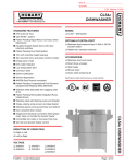
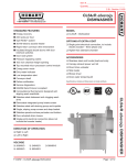
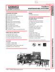
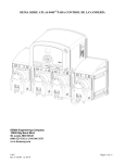
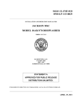
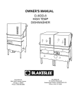
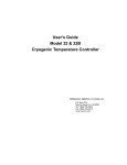
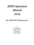
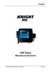
DEMAMasterTM DM-811 Series Installation Manual R TM MADE IN USA I-807 REV. D-37257 9/20/11 Page 1 of 6 DEMAMasterTM DM-811 Series Installation Manual System Overview The DEMAMaster series is designed for long reliable use with simplicity in mind for both the installer and user. The DEMAMaster dispenses using the reliable DEMA peristaltic pump or DEMA solenoid valve for dry detergent applications. The electrical controls are installed in a heavy plastic housing with a sealed cover that uses a Lexan label with visible function indicators. Pumps are available with three different motor/gear box speeds, 15, 60, and 105 RPM. There are micro controllers housed in the unit that control the operation of the pump or valve. By use of the various DEMA control boards, chemical products can be dispensed in a manner that will allow proper usage of the chemical product. Please read all instructions before proceeding with the DEMAMaster installation. Preparation for Installation First step in the installation is to know what type of DEMAMaster is to be installed. The following table will help identify the unit to be installed. This instruction sheet is only for those model numbers listed. Table 1 DEMAMaster General Specifications Model Number DM-811-L-1T DM-811-D-1T DM-811-PL-1T DM-811-PD-1T DM-811-SC-1T DM-811-L-0T DM-811-D-0T DM-811-SC-0T DM-821-L-1T DM-821-PL-1T DM-821-SC-1T DM-821-L-0T DM-821-PL-0T DM-821-SC-0T Hook Up Power Transformer 120/208/240VAC 80-70-1 24VAC None 120/208/240VAC 80-70-1 Pump or Valve Pump (C2) Valve Pump (C2) Valve Pump (C2) Pump (C2) Valve Pump (C2) Pump (C4) 24VAC None Dishroom Room Survey and Mounting A complete survey of the dish machine sight should be completed before the DEMAMaster installation. 1. 2. 3. Locate the power connection points on the dish machine. The data listed in table 1 of this instruction sheet identify the operating voltage of the DEMAMaster unit to be installed. Select location to mount the DEMAMaster on a wall that will allow access to the chemical product containers and the chemical product feeds points on the dish machine. The DEMAMaster should be kept away from moisture releasing machinery and from water being splashed directly on the unit. Mount the DEMAMaster on a wall by use of the supplied hanger. Simply use the 2 screws supplied with the hanger and mount it to the two holes along the top edge on the backside of the DEMAMaster enclosure. Use appropriate wall anchors when mounting on dry wall. Electrical Installation All installations must be in accordance with city, county, state or provincial electrical codes and be performed by a certified electrician. For questions, please contact local licensed electrical contractor. 1. All electrical power must be turned off to the dish or cleaning machine and any other circuit that is to be used for this installation. Lockout and tag procedures must be observed when installing this device. Never open the DEMAMaster enclosure while power is applied. Signals may be active from dish or cleaning machine, even with DEMAMaster power turned off. Use appropriately rated insulated wiring, electrical fixtures and other materials that meet all applicable electrical and building codes. 2. Connect the power to the DEMAMaster. Table 1 specifies the operating voltage of the various models. Units with transformer and terminal block (See Figure 1): Locate the power terminal block inside the DEMAMaster enclosure. Connect the red or “live” wire to the terminal labeled “line”. Connect the “return line” to the appropriate terminal block position based on supply I-807 REV. D-37257 9/20/11 Page 2 of 6 DEMAMasterTM DM-811 Series Installation Manual voltage. The “earth ground” wire must be connected to the terminal block by use of the grounding clip (supplied in installation kit). The power line should be secured by use of a proper electrical fitting through access hole in DEMAMaster enclosure. The power line must also be secured properly between the dish machine or power source and DEMAMaster. Units without transformer and terminal block (see control board instruction sheet): These units are listed as 24VAC 50/60Hz operating voltage. They will most likely pick up the same voltage off of the dish machine. The 24VAC will hook directly up to the control board terminals identified as “24VAC IN”. The power line should be secured by use of a proper electrical fitting through access hole in DEMAMaster enclosure. The power line must also be secured properly between the dish machine or power source and DEMAMaster. Figure 1 Tubing Connections Included in the installation kit is a roll of LDPE tubing to connect from the chemical container, via the pump or valve, and to the dish machine. Liquid Installation (DEMAMaster with peristaltic pump) 1. Measure the length of the LDPE tubing needed from the bottom of the chemical product container to the pump and cut the tubing to proper length. 2. Install the tubing to the pickup tube (Grey PVC) through the compression nut so that the LDPE tubing is within ¼” from other end of pickup tube. Tighten the compression nut to secure. The pickup tube should be placed into the chemical product container. 3. Route the tubing to the suction side of the pump. An arrow on the faceplate indicates the flow direction. Push the tubing into the squeeze tube on the inlet side of the pump approximately 1/2”-3/4” (15-20mm). Secure the tubing together by tightening a cable tie around the squeeze tube. 4. Install the bulkhead fitting with a ¼” compression fitting through the side of the wash tank on the dish machine. The bulkhead fitting should be installed about 2 inches above the water line. 5. Measure the length of the LDPE tubing needed from the pump to the bulkhead fitting on the side of the dish machine. 6. Push the tubing into the squeeze tube on the outlet side of the pump approximately 1/2”-3/4” (15-20mm). Secure the tubing together by tightening a cable tie around the squeeze tube. Dry Installation (DEMAMaster with solenoid valve) 1. Using ¼” O.D. copper tubing run a water line to the DEMAMaster solenoid valve inlet connector (metal compression elbow fitting). 2. Measure the length of the LDPE tubing that is required to feed water from the solenoid valve to the dry bowl feeder. The line should be secured to solenoid valve outlet fitting (1/4” plastic compression fitting) and the inlet of the dry bowl feeder by use of ¼” plastic compression fitting (that should be with the installation kit of the dry bowl feeder). 3. Install the bulkhead fitting through the side of the wash tank on the dish machine. The bulkhead fitting should be installed about 2 inches above the water line. 4. Use a 5/8” I.D. vinyl tubing to connect the barb fitting at the bottom of dry bowl feeder to the bulkhead fitting on dish machine. Note: Cut off all excess tubing and keep tubing away from hot surfaces and sharp edges to prevent damage or leakage. At this point the installation is complete; refer to the control board instructions that are included with the DEMAMaster unit. I-807 REV. D-37257 9/20/11 Page 3 of 6 DEMAMasterTM DM-811 Series Installation Manual 1 10 12 15 16 13 11 General Components Item No 1 2 3 4 5 6 7 8 9 10 DEMA P/N 81-40 81-41 81-6 80-70 81-10-1 44-116-2 44-116-1 81-118-26 81-118-2 81-118-5 80-99 25-C2D 25-C2 25-130-1 Qty Description 1 1 1 1 1 1 1 1 1 1 1 Electrical Enclosure Electrical Enclosure Lid Hinge and Screw Kit Transformer 40VA Terminal Block and Bracket Assembly # 8 X 3/8 HI-LO Screw (Mounting Transformer) # 8 x ½ HI-LO Screw (Mounting Transformer) Detergent Control Board Kit (81.259.1) Rinse Control Board Kit (80.69.5) Probeless Control Board Kit (80.77.4) Coin Cell Battery Type CR2032 (Probeless Board Only) C2 Detergent Pump Head Kit C2 Rinse Pump Head Kit (3 Roller Block) C4 Pump Head Kit J-Pump, Detergent Kit. (Squeeze Tube, Gasket, Screws not included) Valve Assy. Solenoid Cover #8 Hi-Lo Screw Wall Mounting Bracket Kit (not shown) 60 RPM Gear Motor 15 RPM Gear Motor 105 RPM Gear Motor Detergent Squeeze Tube, EPDM, ½”O.D.x ¼”I.D. x 11” Rinse Squeeze Tube, EPDM, ½”O.D.x 3/16”I.D. x 11” Squeeze Tube, EPDM, ½”O.D.x 1/8”I.D. x 11” J-Pump Detergent Squeeze Tube Assy., EPDM, ¼”x ¼” 1 81-118-15 11 12 13 14 15 16 I-807 REV. D-37257 9/20/11 44-123-4B 44-125 44-116-1 81-1 80-59-60MK 80-59-15MK 80-59-105MK 25-65-CE-11 25-65-RE-11 25-65-SE-11 81-177-1 1 1 1 1 1 1 Page 4 of 6 DEMAMasterTM DM-811 Series Installation Manual C2 PUMP ASSEMBLY 4 2 5 6 3 1 Item No. 1 2 3 4 5 6 7 8 8 C2 Pump Replacement Parts Description C2 Pump Head Gasket C2 Pump Head C2 Roller Block (2 roller) C2 Roller Block (3 roller) C2 Face Plate #10-32 X 1-1/2” Machine Screw #10-32 X 2” Machine Screw C2 Det. Pump Head Kit (kit does not include squeeze tube) C2 Rinse. Pump Head Kit (kit does not include squeeze tube) ½”OD x ¼” ID Squeeze Tube EPDM ½”OD x 3/16” ID Squeeze Tube EPDM ½” OD x ¼” ID Squeeze Tube Viton Part No. 25-91-C2 25-67C2-2 25-84C2 25-90C2 25-83C2-2 25-85-18 25-85-19 25-C2D 25-C2 25-65CE-11 25-65RE-11 25-65CV-11 C4 PUMP ASSEMBLY 1 6 2 5 Item No. 1 2 3 4 5 6 I-807 REV. D-37257 9/20/11 3 4 5 C4 Pump Replacement Parts DEMA # Description 25.114C4 C4 Pump Head Gasket 25.129.1 C4 Pump Head Assembly 25.86C4 C4 Roller Block Assembly 25.87C4 C4 Face Plate 25.85.5 #10-32 x 1” Machine Screw 25.89CE.14 Squeeze Tube 5/8” OD x 3/8” ID Page 5 of 6 DEMAMasterTM DM-811 Series Installation Manual J-PUMP ASSEMBLY 5 1 Item No. 1 2 3 4 5 6 2 DEMA No. 81-63-1 81-128-2 25-85-2 81-172-1 81-177-1 81-174-1 3 4 6 J-PUMP ASSEMBLY Description Gasket J-Pump Head 10-32 x ½” Machine Screw, SS J-Pump Detergent Roller Block (2 rollers) J-Pump Detergent Squeeze Tube Assy., EPDM, ¼”x ¼” J-Pump Face Plate Return Policy No merchandise may be returned for credit without DEMA Engineering Company’s written permission. Return Merchandise Authorization (RMA) number required in advance of return. Warranty DEMA products are warranted against defective material and workmanship under normal use and service for one year from the date of manufacture. This limited warranty does not apply to products that have a normal life shorter than one year or failure and damage caused by chemicals, corrosion, improper voltage supply, physical abuse or misapplication. Rubber and synthetic parts such as “O”-rings, diaphragms, squeeze tubing and gaskets are considered expendable and are not covered under warranty. This warranty is extended only to the original buyer of DEMA products. If products are altered or repaired without prior approval of DEMA, this warranty will be void. Defective units or parts should be returned to the factory with transportation prepaid. If inspection shows them to be defective, they will be repaired or replaced without charge. F.O.B. factory DEMA assumes no liability for damages. Return merchandise authorization number to return units for repair or replacement must be granted in advance of return. I-807 REV. D-37257 9/20/11 Page 6 of 6