1
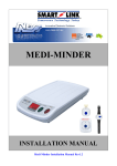
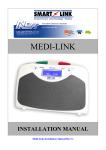
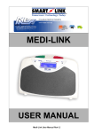
MEDI-LINK GPRS/GSM Part No. 100-824 Part No. 100-825 Part No. 100-827 INSTALLATION MANUAL Medi-Link GPRS/GSM Installation Manual Rev1.30 “A division of NESS CORPORATION PTY LTD” © Copyright SmartLink November 2013 Unit 4/56 Norcal Rd, Nunawading VIC 3131 Australia Tel: +61 3 9875 6400 Facsimile: +61 3 9875 6422 Email: [email protected] Web Site: www.smartlink.com.au Smartlink Medi-Link GPRS/GSM Installation Manual Rev1.30 Document Part Number: 890-438 For products: 100-824 Medi-Link GPRS/GSM Unit 100-825 Medi-Link 3G Unit 100-827 Medi-Link 3G + PSTN Unit © 2012 Ness Corporation Pty Ltd ABN 28 069 984 372 Specifications may change without notice. Ness Corporation manufacturing processes are accredited to ISO9001 quality standards and all possible care and diligence has been applied during manufacture to ensure the reliable operation of this product. However there are various external factors that may impede or restrict the operation of this product in accordance with the product’s specification. These factors include, but are not limited to: 1. Erratic or reduced radio range. Ness radio products are sophisticated low power devices, however the presence of in-band radio signals, high power transmissions or interference caused by electrical appliances such as wireless routers, cordless phones, computers, TVs and other electronic devices may reduce the range performance. While such occurrences are unusual, they are possible. In this case it may be necessary to either increase the physical separation between the Ness receiver and other devices or if possible change the radio frequency or channel of the other devices. 2. Unauthorised tampering, physical damage, electrical interruptions such as mains failure, electrical spikes or lightning. 1. Contents 1. Contents.......................................................................................................... 1 2. Equipment List.............................................................................................. 2 3. Overview..........................................................................................................2 4. SIM Card.......................................................................................................... 3 5. SIM Card Installation....................................................................................4 6. Quick Setup Guide....................................................................................... 5 7. Programming Using the Cancel & Help Button................................... 6 8. Product Type (Default = ADEMCO)..........................................................6 9. Programming Medi-Link GPRS/GSM Unit............................................. 7 9.1 To Enter Program Mode................................................................................... 7 9.2 Programming CLIENT ACCOUNT.................................................................. 7 9.3 Programming PHONE NUMBERS “GSM” – “If Required”.......................... 7 9.4 Programming SERVER “GPRS” – “If Required”...........................................8 9.5 Programming SYSTEMS.................................................................................. 8 9.6 Programming CELLULAR................................................................................ 9 9.7 Programming REPORTS................................................................................10 9.8 To EXIT PROGRAM Mode............................................................................ 10 10. Signal Quality/Strength.......................................................................... 11 11. Setting the Time and Date..................................................................... 11 12. Up/Download Programmer Software..................................................12 13. Medi-Link UDP/SERVER Reporting.................................................... 13 1 . 2. Equipment List Medi-Link GPRS/GSM Unit (NB: Sim Card not included) Antenna Waterproof Pendant (Wristwatch & Neck Chain included) 17V AC 300mA Plug Pack (with integral earth) Medi-Link GPRS/GSM User Manual Medi-Link GPRS/GSM Installation Manual 3. Overview The Medi-Link GPRS/GSM unit uses a Cellular Module to report using the mobile network. The Cellular Module requires a SIM to connect to a particular network. The SIM itself has various attributes that can be set by the network provider. Some of these options are available for Medi-Link GPRS/GSM use, some can only be viewed and some only the network provider can access. The Medi-Link GPRS/GSM unit connects up to the mobile network so some aspects are similar to your everyday mobile phone. 2 4. SIM Card NB: Sim Card not included in the Medi-Link GPRS/GSM unit. Caution should be taken when purchasing SIM cards so that they have the desired network features available for Medi-Link GPRS/GSM unit to function correctly. *Pin number must be Disabled* The Medi-Link GPRS/GSM unit requires a SIM card (just like any mobile phone) from a service provider. Likewise, Medi-Link GPRS/GSM unit has ‘Program 10. CELLULAR-> SIM Identity’ to view the unique international mobile equipment identity (IEMI) number. The SIM itself is a small memory card that stores information about usage, account, and network. When the Medi-Link GPRS/GSM unit is powered the cellular module uses the information from the SIM to determine the type of communication the network provider has allowed for the particular SIM. As a result some features may not be available due to network restrictions. The mobile network offers specific channels designed to efficiently communicate in a particular manner. The most common of these is the ‘Voice channel’. This channel assumes the communication is voice in nature and thus processes the signal by sampling, slicing into packets and compressing before transmitting,… and on the other side ….. uncompressing, joining the packets back together and converting back to some sort of analogue voice signal. This is ideal for voice as once it has been processed the voice can not deteriorate in the transmission process. However this can process out the fine detail that is transmitted in the modem signal. For this reason the service providers have introduced the ‘Data channel’ where data can be transmitted without the voice processing. When the Medi-Link GPRS/GSM unit reports, it generates GPRS through the airways and or DTMFs through the voice channels. Again the network processes can affect these signals, as such Medi-Link unit uses network generated DTMFs on alternate reports in GSM mode only. Some networks may attempt to recognise DTMF on voice channel and convert the signal to network generated DTMFs. 3 5. SIM Card Installation The Medi-Link GPRS/GSM unit has a SIM socket which is located in the Battery compartment. To access, undo the screw and remove the Battery Hatch. 1 x M3.5 screw Model No. Battery Hatch GPRS/GSM 304 The SIM socket is located beside the battery so remove the Battery first. The SIM socket is a push-push type which is very easy to use. The SIM card needs to be placed contactside down with the notched corner toward the socket (shown in the diagram below) then pushed in until it clicks into place. When correctly inserted, the edge of the SIM card will not extend into the battery compartment. Upon a second push the SIM card will click out of the SIM socket ready for removal. SIM card When the SIM card is correctly inserted, sufficient room is available for the Battery. Replace the Battery. Care must be taken with the Battery Leads, so that they are tucked away neatly before placing the Battery Hatch. 4 Neatly tuck wire in here. Clip the Battery Hatch into place and tighten the screw. The Medi-Link GPRS/GSM is now ready for use. Power the Medi-Link GPRS/GSM by connecting the AC power supply and switching the Battery Switch to ON. At this stage the Medi-Link GPRS/GSM is attempting to initiate communication with the GSM mobile towers which may take several seconds before the Medi-Link GPRS/GSM has established a link. To ensure the Medi-Link GPRS/GSM has the best GSM communication, use the CELLULAR->Signal Quality->’ feature and place the Medi-Link GPRS/GSM where signal quality is at it’s highest. The remaining setup required is as per Medi-Link unit (standard). 6. Quick Setup Guide 1. Insert the SIM Card into the Medi-Link GPRS/GSM Unit (refer to Section 5). 2. Supply Power to the Medi-Link GPRS/GSM Unit by: - Connecting the AC Plug Pack to a Power outlet and connect the Plug to “POWER” underside the Medi-Link GPRS/GSM Unit. - Sliding the Battery “ON/OFF” Switch to the “ON” position underside the Medi-Link GPRS/GSM Unit. 3. While in Program Mode, enter the: - 4 digits “Client Account” Code/Number - Primary Phone Numbers for GSM (If required) “Ph.1 & 2 Primary”) - Server 1 Primary Address and Port Number for GPRS (If Required) 4. After Exiting Program Mode, set the Time & Date by following the instructions on Section 11. (Setting the Time & Date). ATTENTION: The correct Time and Date MUST be SET in order for the Medi-Link GPRS/GSM Unit to function to its full potential and specifications. This can be done either via the Red and Green Buttons or via the UpDownload Programmer Software after exiting Program Mode. 5 7. Programming Using the Cancel & Help Button The easiest way to program the Medi-Link GPRS/GSM unit is to use the large CANCEL (Green) Button and the HELP (Red) Button. 1 Press the CANCEL (Green) Button on the Medi-Link GPRS/GSM unit to scroll through the Main Menu Options or the Sub Menu Options. 2 Press the HELP (Red) Button on the Medi-Link GPRS/GSM to view the programmed value for that option. The values will be displayed flashing. To step through values, press the HELP (Red) Button again. 3 To store an option selected, press the CANCEL (Green) and HELP (Red) Buttons at the same time. The Medi-Link GPRS/GSM unit will beep twice while flashing the display to acknowledge that the option has been selected. 8. Product Type (Default = ADEMCO) NB: The Product Type is programmed by entering the Special Code on the Medi-Link GPRS/GSM unit. This will reset all Programming Options and will have to be completely reprogrammed again in the new mode. If the code is unknown then the Medi-Link unit will default to the previous Product Type and it’s Option Programming will be maintained. The Medi-Link unit will remain in this Mode for only 5 minutes if the code hasn’t been entered. 1. Hold down the CANCEL (Green) and HELP (Red) Buttons and Power up the Unit. 2. The Medi-Link GPRS/GSM unit will Chime and then Beep Once while PRODUCT TYPE is displayed to indicate that it is in Product Programming. 3. Using the CANCEL (Green) and HELP (Red) Buttons, a Code may be entered as follows: a. MEDI-LINK GPRS/GSM “ADEMCO” - Press CANCEL, CANCEL, CANCEL, HELP b. MEDI-LINK GPRS/GSM “BRITISH DTMF” - Press HELP, HELP, CANCEL, HELP c. MEDI-LINK GPRS/GSM “CONTACT ID” 4. 6 - Press CANCEL, HELP, CANCEL, HELP Press the CANCEL (Green) and HELP (Red) Buttons at the same time to acknowledge end of Product Programming. The Medi-Link GPRS/GSM unit will Beep Once to indicate that it is now in Options Programming. 9. Programming Medi-Link GPRS/GSM Unit 9.1 To Enter Program Mode 1. Slide the Battery “ON/OFF” Switch to the “ON” position & plug the AC Plug Pack to a Power Outlet. 2. The Medi-Link unit will Chime, Beep once and then display the Product Type and Version Number to indicate that it is in Programming Options. SMARTLINK Tomorrows Technology Today ADEMCO 1.4 1.CLIENT ACCOUNT NB: If NO Buttons on the Medi-Link unit or the Radio Key Pendants have been pressed within 5 minutes, the Medi-Link will revert back to Normal Operation Mode (NB: A Client Account No. and at least one Phone No. must be programmed in for the Medi-Link unit to Exit Program Mode and enter Normal Operation Mode). 9.2 Programming CLIENT ACCOUNT Option ADEMCO 1.4 1. CLIENT ACCOUNT Descriptions: “1. CLIENT ACCOUNT” is displayed. Press the HELP Button. “Client Account” is displayed. Press the HELP Button. 1. Press the HELP Button again to view programmed Client Account Number. 1. CLIENT ACCOUNT ↑↓ Client Account Client Account ↑↓ - 2. Pressing the HELP Button again to step through the digits 0, 1, 2, 3, 4, 5, 6, 7, 8, 9 & -. To STORE each digit, press the CANCEL and HELP Buttons at the same time. The Medi-Link unit will beep 3 times to acknowledge that the digit has been programmed. Repeat this process until all digits are programmed. Note: programmed a “ - ” as the first digit will delete the Client Account Numbers. 3. Press the CANCEL Button to move to the next Program Option. 9.3 Programming PHONE NUMBERS “GSM” – “If Required” Option ADEMCO 1.4 2A.PHONE NUMBERS Descriptions: (Note: up to 30 Digits Maximum) “2A. PHONE NUMBERS” is displayed. Press the HELP Button. “Ph.1 Primary” is displayed. Press the HELP Button. 2A.PHONE NUMBERS ↑↓ Ph.1 Primary Ph.1 Primary ↑↓ - 1. Pressing the HELP Button again to step through the digits 1,2,3,4,5,6,7,8,9,0, * Star, # Hash, and – Pause. To Store each digit, press the CANCEL and HELP Buttons at the same time. The Medi-Link unit will beep 3 times to acknowledge that the digit has been programmed. Repeat this process until all digits are programmed. NOTE: programmed a “ - ” as the first digit will delete the Phone Numbers. 2. Press the CANCEL Button to move to the next Program Option. 7 “Ph.2 Primary” is displayed. Press the HELP Button. 2A.PHONE NUMBERS ↑↓ Ph.2 Primary Ph.2 Primary ↑↓ - 1. Pressing the HELP Button again to step through the digits 1,2,3,4,5,6,7,8,9,0, * Star, # Hash, and – Pause. To Store each digit, press the CANCEL and HELP Buttons at the same time. The Medi-Link unit will beep 3 times to acknowledge that the digit has been programmed. Repeat this process until all digits are programmed. NOTE: programmed a “ - ” as the first digit will delete the Phone Numbers. 2. Keep Pressing the CANCEL Button to move to the next Program Option. 9.4 Programming SERVER “GPRS” – “If Required” Option ADEMCO 2B. SERVER Descriptions: (IP Address & Port Programming) 1.4 2B. SERVER ↑↓ Svr.1 Primary Svr.1 Primary ↑↓ Address Address ↑↓ 255.255.255.255 Svr.1 Primary ↑↓ Port Port ↑↓ - “2B. SERVER” is displayed. Press the HELP Button. “Svr.1 Primary” is displayed. Press the HELP Button. 1. Pressing the HELP Button again to step through the numbers from 0 up to 255. To Store each numbers, press the CANCEL and HELP Buttons at the same time. The Medi-Link unit will beep 3 times to acknowledge that the numbers has been programmed. Repeat this process until all IP Address numbers are programmed in. 2. Press the CANCEL Button Twice to move to the next Program Option. “Svr.1 Port” is displayed. Press the HELP Button. 1. Pressing the HELP Button again to step through the digits 1,2,3,4,5,6,7,8,9, and 0. To Store each digit, press the CANCEL and HELP Buttons at the same time. The Medi-Link unit will beep 3 times to acknowledge that the digit has been programmed. Repeat this process until all 4 digits are programmed in. 2. Keep Pressing the CANCEL Button to move to the next Program Option. 9.5 Programming SYSTEMS Option ADEMCO 1.7 9. SYSTEMS 9. SYSTEMS ↑↓ Rpt Pre Time 9. SYSTEMS ↑↓ Rpt Tone Time 9. SYSTEMS ↑↓ Rpt QuietTime 9. SYSTEMS ↑↓ RptBetwnTime 8 Descriptions: Warning! Do not adjust, refer to SmartLink. “9. SYSTEM” is displayed. Press the HELP Button. Report Pre Time (default = 10 x 10mS) V1.7 Onwards NB: Do not adjust, refer to SmartLink if required. Report Tone Time (default = 4 x 10mS) V1.7 Onwards NB: Do not adjust, refer to SmartLink if required. Report Pre Time (default = 4 x 10mS) V1.7 Onwards NB: Do not adjust, refer to SmartLink if required. Report Pre Time (default = 100 x 10mS) V1.7 Onwards NB: Do not adjust, refer to SmartLink if required. 9.6 Programming CELLULAR Option ADEMCO 1.4 10. CELLULAR 10. CELLULAR ↑↓ Identity 10. CELLULAR ↑↓ Type Descriptions: Warning! Do not adjust, refer to SmartLink. “10. CELLULAR” is displayed. Press the HELP Button. “Identity” is displayed. Press the HELP Button. The Medi-Link unit displays the Identity Module numbers eg. “35976903185511” & cannot be changed but are there for your reference only. Press the CANCEL Button to move to the next Program Option. “Type” is displayed. Press the HELP Button. The Medi-Link unit displays the Module Type eg. “SIMCOMSIM5216J” & cannot be changed but are there for your reference only. Press the CANCEL Button to move to the next Program Option. 10. CELLULAR ↑↓ Revision “Revision” is displayed. Press the HELP Button. The Medi-Link unit displays the Revision eg. “1575B05SIM5216” & cannot be changed but are there for your reference only. Press the CANCEL Button to move to the next Program Option. 10. CELLULAR ↑↓ SIM Identity “SIM Identity” is displayed. Press the HELP Button. The Medi-Link unit displays the SIM Identity eg “89610188427072” & cannot be changed but are there for your reference only. Press the CANCEL Button to move to the next Program Option. 10. CELLULAR ↑↓ SIM Provider “SIM Provider” is displayed. Press the HELP Button. The Medi-Link unit displays the SIM Provider eg “Telstra Mobile” & cannot be changed but are there for your reference only. Press the CANCEL Button to move to the next Program Option. 10. CELLULAR ↑↓ SIM APN “SIM APN” is displayed. Press the HELP Button. The Medi-Link unit displays the SIM APN eg “Telstra.intern” & cannot be changed but are there for your reference only. Press the CANCEL Button to move to the next Program Option. 10. CELLULAR ↑↓ Poll Time “Poll Time” is displayed. Press the HELP Button. The Medi-Link unit displays the Poll Time eg “60” as the Default. Press the HELP Button to change from “0” to “255” Minutes. Press the CANCEL Button to the next Program Option. 10. CELLULAR ↑↓ Mode 10. CELLULAR ↑↓ In Level 10. CELLULAR ↑↓ In Attenuation 10. CELLULAR ↑↓ Out Level 10. CELLULAR ↑↓ OutAttenuatio Mode (default = 5) NB: Do not adjust, refer to SmartLink if required. In Level (default = 0) NB: Do not adjust, refer to SmartLink if required. In Attenuate (default = 255) NB: Do not adjust, refer to SmartLink if required. Out Level (default = 2) NB: Do not adjust, refer to SmartLink if required. Out Attenuate (default = 127) NB: Do not adjust, refer to SmartLink if required. 9 Sidetone Gain (default = 3) 10. CELLULAR ↑↓ Sidetone Gain NB: Do not adjust, refer to SmartLink if required. Network AMR (default = Disable) 10. CELLULAR ↑↓ Network AMR NB: Do not adjust, refer to SmartLink if required. Network Rate (default = 1) 10. CELLULAR ↑↓ Network Rate NB: Do not adjust, refer to SmartLink if required. “Signal Quality” is displayed. Press the HELP Button. The unit displays the Cellular Signal Quality from 1 to 31 (10 to 31 good, 6 to 9 average, below 6 may need relocation or alternate Carrier). Press the CANCEL Button to move to the next Program Option. Default – Default all the PREFERENCES Programming Options 10. CELLULAR ↑↓ Signal Quality Press the CANCEL and HELP Buttons at the same time. The Medi-Link GPRS/GSM unit will beep 3 times to acknowledge that ALL the Cellular Programming Options has been Defaulted. Press the CANCEL Button to move to the next Program Option. 10. CELLULAR ↑↓ Default 9.7 Programming REPORTS Option ADEMCO 13. REPORTS Descriptions: Warning! Do not adjust, refer to SmartLink. 1.7 “13. REPORTS” is displayed. Press the HELP Button. NB: This Option is only available on the Medi-Link 3G+PSTN unit V1.7 (100-827). Do not adjust, refer to SmartLink. Press the CANCEL Button until “Mode” is displayed. Press the HELP Button. “8-PSTN,GSM,GPRS” is displayed as the Default. 0-GSM ONLY 1-GPRS ONLY 13. REPORTS ↑↓ Mode 2-GPRS,GSM 3-GPRS,PSTN 4-GPRS,GSM,PSTN 5-PSTN ONLY 6-PSTN,GPRS 7-PSTN,GPRS,GSM 8-PSTN,GSM,GPRS (as the Default) Press the CANCEL Button to move to the next Program Option. 9.8 To EXIT PROGRAM Mode Option ADEMCO 1.4 15. EXIT PROGRAM 10 Descriptions: 10. Signal Quality/Strength 9 Mon, 1:23 The Medi-Link GPRS/GSM Unit displays the Day and Time and the Signal Quality from 1 to 9 (Top right hand corner “flashing”). 1 being Weakest Signal – 9 being Strongest Signal. The MediLink GPRS/GSM unit updates the Signal Strength every minute. 11. Setting the Time and Date The Medi-Link GPRS/GSM unit has an inbuilt Clock & Calendar that is backed up by the system battery and will remain even in the event of a power failure. If you require the time and day to be changed for any reason then perform the following steps: 9 Mon, Set Time ↑↓ Set Date ↑↓ 1:23 16:56 07-Nov-12 9 Wed, 4:56 1. While the Medi-Link unit is in standard operation mode, Press and Hold down the CANCEL Button for 10 seconds until “Set Time” is displayed. 2. Press the HELP Button until the correct hour is displayed. Once the hour is set, press the CANCEL Button to begin setting the minutes. In a similar fashion press the HELP Button until the correct minutes are displayed. 3. After the minutes have been set, press the CANCEL Button to move onto setting the Year, Month and Day. 4. While in the “Set Date” menu, press the HELP Button until the correct year is selected. After the year has been set, press the CANCEL Button to move onto setting the month. Press the HELP Button until the correct month is selected. After the month has been set, press the CANCEL Button to move onto setting the day. Press the HELP Button until the correct day is selected. 5. Finally, press the CANCEL Button to Exit the Menu and save changes. Note: the Medi-Link unit will automatically exit (drop out) of the Set Time & Date Menu if the Cancel or Help Button had not been pressed within 5 Minutes. 11 . 12. Up/Download Programmer Software NB: To use the Up/Download Programmer Software, the SmartLink Medi-Link unit can either be programmed via the External Modem or Direct DB9 Programming Lead (Part No. 450-185). For more information, refer to the SmartLink Up/Download Programmer Installation Manual. a. Using the Direct Programming Lead: (Part No. 450-185): b. External Modem (Fax Defeat): Ensure that the PSTN (Land Line) has the Caller ID Enabled. The Medi-Link unit will Call Back to established the Link for the UpDownload Programmer. Medi-Link CELLULAR Medi-Link CELLULAR/PSTN 12 13. Medi-Link UDP/SERVER Reporting The Medi-Link (Cellular) has an internal GPRS/GSM module to perform network reporting. The Medi-Link microcontroller communicates with this module by strings. Basically the microcontroller makes a request and the module responds. When the operation is successful the process steps through the following states. (Displayed bottom right hand corner as occurring). - [ntwO] … 2 attempts (8 sec) … GPRS/GSM module establishes connection with a Cellular Network. - [prtO] … 5 attempts (20 sec) …GPRS/GSM module opens a UDP port on the Network. - [cnct] … 2 attempts (8 sec) … GPRS/GSM module connects to a receiving Server via the UDP . . - [rpt] … Port. 2 attempts (8 sec) … Medi-Link transmits report to receiving Server. - [rsp] … 1 attempt (14 sec) … Medi-Link waits for response for receiving Server. NB: If a response is not received from the Server, then the Medi-Link closes the Port. - [prtC] … 2 attempts (2 sec) … GPRS/GSM module closes a UDP port on the Network. - [ntwC] … 2 attempts (2 sec ) … GPRS/GSM module closes connection with Cellular Network NB: if continually displaying any one of the above then whatever stays on display (Bottom right hand corner) is where the problem has occurred for service diagnostics. See below… CALL Unit [ntw0] [NOTE: If response was not received from the Server, the Medi-Link performs up to 10 reporting attempts rotating around the programmed Servers. There is no delay between the attempts.] These states occur after the GPRS/GSM module has made contact with the service provider’s access point. The GPRS/GSM manages the access point connection internally. The GPRS/GSM module may come across network communication issues. The module will respond with error messages instead of the expected message. These error messages can be analysed and determine exactly what is happening. The time to report via the UDP port is usually instant. The microcontroller requests and the GPRS/GSM module responses are generally quick. At times however the response may be slower as the GPRS/GSM module waits for communication from the access point and may respond with errors. In this case each request waits for the response. So this process may extend to a minute in unusual circumstances. The Medi-Link attempts to report 10 times via the UDP port connection. If it is not successful than it will attempt to report through the GSM channel if phone are numbers entered (again 10 attempts, then 5 minutes, then 9 attempts hourly). NB” If it fails to get through in GPRS mode “Report fail” will be displayed until the unit finally connects either 13 13. Medi-Link UDP/SERVER Reporting The Medi-Link (Cellular) has an internal GPRS/GSM module to perform network reporting. The Medi-Link microcontroller communicates with this module by strings. Basically the microcontroller makes a request and the module responds. When the operation is successful the process steps through the following states. (Displayed bottom right hand corner as occurring). - [ntwO] … 2 attempts (8 sec) … GPRS/GSM module establishes connection with a Cellular Network. - [prtO] … 5 attempts (20 sec) …GPRS/GSM module opens a UDP port on the Network. - [cnct] … 2 attempts (8 sec) … GPRS/GSM module connects to a receiving Server via the UDP . . - [rpt] … Port. 2 attempts (8 sec) … Medi-Link transmits report to receiving Server. - [rsp] … 1 attempt (14 sec) … Medi-Link waits for response for receiving Server. NB: If a response is not received from the Server, then the Medi-Link closes the Port. - [prtC] … 2 attempts (2 sec) … GPRS/GSM module closes a UDP port on the Network. - [ntwC] … 2 attempts (2 sec ) … GPRS/GSM module closes connection with Cellular Network NB: if continually displaying any one of the above then whatever stays on display (Bottom right hand corner) is where the problem has occurred for service diagnostics. See below… CALL Unit [ntw0] [NOTE: If response was not received from the Server, the Medi-Link performs up to 10 reporting attempts rotating around the programmed Servers. There is no delay between the attempts.] These states occur after the GPRS/GSM module has made contact with the service provider’s access point. The GPRS/GSM manages the access point connection internally. The GPRS/GSM module may come across network communication issues. The module will respond with error messages instead of the expected message. These error messages can be analysed and determine exactly what is happening. The time to report via the UDP port is usually instant. The microcontroller requests and the GPRS/GSM module responses are generally quick. At times however the response may be slower as the GPRS/GSM module waits for communication from the access point and may respond with errors. In this case each request waits for the response. So this process may extend to a minute in unusual circumstances. The Medi-Link attempts to report 10 times via the UDP port connection. If it is not successful than it will attempt to report through the GSM channel if phone are numbers entered (again 10 attempts, then 5 minutes, then 9 attempts hourly). NB” If it fails to get through in GPRS mode “Report fail” will be displayed until the unit finally connects either 14 through GPRS or GSM. If unit is only programmed in GPRS and it fails to communicate it will then wait for the next poll. If poll is successful then it will also send through any previous alarms that are in the cue that did not get through, time dated and stamped accordingly as they happened. Upon a successful UDP port report and if programmed to do so, the Medi-Link will start polling the receiving Server at 60 Minute intervals (Default value - programmable). These polling reports are identical to any other Medi-Link report but is unique in its contents so the receiving Server will reset it’s time for the next expected report. “A division of NESS CORPORATION PTY LTD” © Copyright SmartLink November 2013 Unit 4/56 Norcal Rd, Nunawading VIC 3131 Australia Tel: +61 3 9875 6400 Facsimile: +61 3 9875 6422 Email: [email protected] Web Site: www.smartlink.com.au 15