1
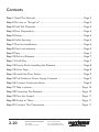
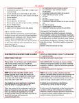
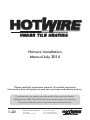
Hotwire Installation
Manual July 2014
Please read this instruction manual. It includes important
information that will assist you and save you time and money such as,
To calculate the wire spacing start with the M2 of the area to be heated.
Multiply this by 1000. Then divide this answer by the length of the element.
The answer will be the space at which the element should be laid.
1-20
Hotwire (Australia Head Office)
Po Box 543,
Mount Evelyn Vic 3796
Phone 1300 797 060
Fax +61 (03) 8678 1337
www.hotwireheating.com.au
Contents
Step 1 Read This Manual ................................................................. Page 3
Step 2 Pre wire or “Rough In” ........................................................... Page 3
Step 3 Cold Tail Channels ................................................................. Page 4
Step 4 Floor Preparation ................................................................... Page 4
Step 5 Primer ................................................................................... Page 4
Step 6 Cable Spacing ....................................................................... Page 5
Step 7 Plan the installation ............................................................... Page 6
Step 8 Check the element................................................................. Page 6
Step 9 Tape...................................................................................... Page 7
Step 10 Roll out Element .................................................................. Page 7
Step 11 Half Way ............................................................................. Page 7
Step 12 Nearly Finish Installing the Element ...................................... Page 8
Step 13 More Tape ........................................................................... Page 8
Step 14 Install the Floor Probe .......................................................... Page 9
Step 15 Pull Cables to Power Supply Contents ................................... Page 9
Step 16 Connect Continuity Alarm .................................................... Page 9
Step 17 Take a picture.................................................................... Page 10
Step 18 Protecting The Element...................................................... Page 10
Step 19 Pour the Screed ................................................................. Page 11
Step 20 Notice to Tilers .................................................................. Page 11
Step 21 Connect The Thermostat ................................................... Page 11
2-20
Hotwire (Australia Head Office)
Po Box 543,
Mount Evelyn Vic 3796
Phone 1300 797 060
Fax +61 (03) 8678 1337
www.hotwireheating.com.au
installed on top of water proofing. If unsure
please contact the manufacturer of the brand
you are using. If you are using Ardex products you can use Arditex NA.
Step 1 Read This
Manual
2) Primer is not required over most waterproofing membranes. Please speak to your
tiler or waterproofer about this. Hotwire accepts no responsibility for incorrect products
used in this step.
Please read this manual. It includes everything you need to know to successfully install
Hotwire.
Incorrect installation of Hotwire may lead to
any warranty claim being denied.
In some States and Territories of Australia the
installation of Hotwire Under Tile
Heating must be performed in its entirety by
a licensed electrical contractor. Whist in
others a licensed contractor is only required
for the connections to the thermostat.
Please check with your local electrical
authority or Electrical Contractor to verify
the requirements applicable to your State or
Territory.
This product is Under Tile Heating and not
In Screed heating. If you require In Screed
Heating please contact Hotwire or your
place of purchase and the correct element
can be sent.
Mount Flush Box Vertically.
Provide power suitable
for load of element to
flush box. E.g. 800 watts
Insert draw wire from
flush box to floor. This
will enable you to pull the
coldtails to the thermostat.
Note: Water Proofing
You can install Hotwire under or on top of the
waterproofing.
3-20
Hotwire (Australia Head Office)
Po Box 543,
Mount Evelyn Vic 3796
1:Power supply. You will need power capable
of running the Hotwire element you are
installing. Eg 800 watts
3:Draw Wire. You will need a draw wire
through the wall cavity or chased into wall (if
brick) and run through conduit.
This element must be installed immediately
under the tile. If a screed it being laid to create a “Fall” or is to level the floor, this element must be installed on top of the screed.
1) Most self levelling products cannot be
Three things are required before Hotwire can
be installed. Please see the diagram.
2:Flush Box. A vertically flush box will need to
be installed. This is a standard light switch /
power point plate.
The Hotwire element cannot be cut,
shortened or lengthened in any way.
However please note the following,
Step 2 Pre wire or
“Rough In”
NSW: (Optional in other states)
Install conduit 100 mm out
onto floor and 100mm into
wall cavity. Run draw wire
through conduit
Phone 1300 797 060
Fax +61 (03) 8678 1337
www.hotwireheating.com.au
Step 3 Cold Tail
Channels
Step 4 Floor
Preparation
Before you do too much you will need to dig
out three channels for the cold tails and for
the floor probe. See the pictures following.
The floor needs to be completely clean.
The cold tails are conductive cables that are
fitted to each end of the element. As the title
says they are cold and it is this part of the
cable that runs up the wall cavity. The join
between the element and the cold tail is a bit
thicker than the rest of the cable so you will
need to dig a small channel. Your hammer
drill should do the job. Each channel should
be 150 mm long. The Cold Tail join must be
completely buried under the tile. Failure to do
so will void your warranty.
The third channel is for the floor probe for
the thermostat. We will explain about that
when you are nearly finished the installation.
Sand, lumps of gyprock glue etc will affect
your Hotwire installation. So make sure you
clean the floor well. Sweep up all the dust,
a once over with the vacuum is also a good
idea if you have one handy.
Step 5 Primer
We prefer that you lay a 4mm thick self leveling screed over the element (more on that
later). Fibre Glass mesh can also be used.
However in either case the floor will need to
be primed to assist the tiler.
You need to cover the floor well but keep in
mind the thicker you do it the longer it will
take to dry and the longer it will be before
you can start installing Hotwire.
We recommend Ardex Multiprime.
Now you have the preliminaries done you
can get down to installing Hotwire.
4-20
Hotwire (Australia Head Office)
Po Box 543,
Mount Evelyn Vic 3796
Phone 1300 797 060
Fax +61 (03) 8678 1337
www.hotwireheating.com.au
Step 6 Cable Spacing
This is really important to an excellent
Hotwire installation, so please read this
carefully.
Calculate the EXACT m2 of the area to
be heated. We don’t normally heat under
anything that is fixed. For example Vanity’s,
WC’s in bathrooms and Kitchen Cupboards
and permanent Entertainment Units in living
areas.
It is a good idea to cut a jig to the size you
need it rather than use a tape measure the
whole time. A off cut of wood is fine, in the
picture we used an off cut of electrical cable.
Take the m2 you are left with and multiply it
by 1000 (this is to bring the measurement to
square millimeters). Then divide that answer
by the length of the element. This is printed
on the side of the spool. The answer will be
the cable spacing and should be between
50 and 75 mm. If your answer is outside this
check your measurements again as you have
made a mistake or have the wrong element.
If this is the case do not proceed with the
installation.
Cable Spacing = M2 of floor X 1000
_______________
Length of Cable
The above formula is a good guide but does
not take into account the loops at the end of
the cable runs so take 5% off your answer. So
for example if your answer was 65 mm start
installing the cable at 61mm apart.
5-20
Hotwire (Australia Head Office)
Po Box 543,
Mount Evelyn Vic 3796
Note for areas over 20 m2.
If your area is over 20 m2 you have been supplied with two elements. These must be run in
parallel and not joined together. Basically you
have to install one element on one half of the
floor and the other on the other half. So do
the above measurement with 50% of the m2.
Phone 1300 797 060
Fax +61 (03) 8678 1337
www.hotwireheating.com.au
Step 7 Plan the
installation
aged during transit. We check every element
before it leaves our warehouse but there is
the possibility that it may get damaged by a
courier.
This is a step where you can come undone if
you don’t plan properly.
If you have a multimeter then you can check
the cable against the following table.
The Hotwire element must start and finish
in the same place and CANNOT be cut or
shortened in any way. So have a look at the
room and work out what is the most logical
and simple way to run the cable around that
room.
Watts*
You want to be doing as many long runs as
possible.
Start/Finish
Start/Finish
Bathroom
Living Area
Cable
Length
Ohms
Amps
200
17
264.50
0.87
300
25
176.33
1.30
400
35
132.25
1.74
500
43
105.80
2.17
600
53
88.17
2.61
700
63
75.57
3.04
800
72
66.13
3.48
900
82
58.78
3.91
1000
91
52.90
4.35
1250
118
42.32
5.43
1500
141
35.27
6.52
1750
168
30.23
7.61
Start/Finish
2000
189
26.45
8.70
2500
235
21.16
10.87
3000
294
17.63
13.04
If you don’t have a multimeter don’t panic we
have you covered too.
Kitchen
Try and leave the longest wall to last. That
way if you have a little too much or too little
cable left you can make an easy adjustment
by coming a bit further away or going right
up close to the wall. Neither option will affect
the heating of the room in any way.
Step 8 Check the
element
Before installing the element it is always a
good idea to ensure it has not been dam-
6-20
Hotwire (Australia Head Office)
Po Box 543,
Mount Evelyn Vic 3796
In the Hotwire Box is a continuity alarm. It is
a small black box with 3 cables coming off
the end.
1: Remove small white sticker over
“On / Off” Switch
2: Fix the Black clip to the Brown wire of the
element.
3: Fix the Red clip to the Blue wire of the
element.
4: Fix the Green clip to one end of the Green
(earth) wire.
5: Switch the tester on.
6: A Red Light then shows that the tester is
on and working.
Phone 1300 797 060
Fax +61 (03) 8678 1337
www.hotwireheating.com.au
7: If you have a fault the tester will start
“Beeping”
If the alarm does not beep you are good to
keep installing. There is also another use for
the alarm so keep it handy, more about that
after the element is down.
Step 9 Tape
You will need lots of bits of the cloth tape
that it is included in the box. Rip off pieces
about 60 mm long. A good rule of thumb is
when you think you have enough rip off twice
as much again and you should be good to
go. Just stick the pieces up a door frame or
window sill.
Then start spreading the element around the
floor using the jig you cut earlier.
Step 11 Half Way
Step 10 Roll out
Element
You are now ready to start rolling out the
element and sticking it down.
Stick one end in the cold tail grove you cut
earlier. Do not put any part of the cold tail
join inside the wall cavity. It must be completely buried in the floor.
7-20
Hotwire (Australia Head Office)
Po Box 543,
Mount Evelyn Vic 3796
You will notice a half way marker. It is little
piece of tape around the element. When
you see this stop and look at where you are
up to. If you are not sure if you are half way
through the floor check your measurements.
Measure the remaining m2 and use 50% of
the cable length to check if you are on target. If you are a little more or under half way
you can spread the cable runs out or close
them up a bit. However only do this is if the
difference is a mm or 2. If it is greater than
this you may need to roll the cable up and
change the spacing.
Phone 1300 797 060
Fax +61 (03) 8678 1337
www.hotwireheating.com.au
Step 12 Nearly Finish
Installing the Element
Step 13 More Tape
Stick any proud bits of element down. Some
of the loops may have popped up a bit. You
will also need to run a strip of cable right
across the whole floor to ensure the cable
does not get moved when installing the leveller. It is a good idea to run right across the
floor every meter.
When you are nearly finished (only 4 or 5
meters of cable left) you will need to go
in reverse. Roll off all the cable and stick
the second cold tail down. Then make the
remainder of the element fit in the remaining
space.
You may find it necessary to make one run
a little shorter or close the cables up a bit.
This is Okay as long as it is not a high traffic
point.
In the picture you will notice the last run is
a little short. This is perfectly allright as long
as it is not the cable run right in front of the
vanity!
If you are really stuck you can eliminate an
area such as behind a door or down the sides
of a Vanity unit. Just check with the homeowner to ensure they are aware so that you
don’t have any problems later.
8-20
Hotwire (Australia Head Office)
Po Box 543,
Mount Evelyn Vic 3796
Phone 1300 797 060
Fax +61 (03) 8678 1337
www.hotwireheating.com.au
Step 14 Install the
Floor Probe
You now need to install the floor probe. It
should be in the box with the thermostat.
Stick the probe in the grove you cut earlier.
Make sure you don’t stick any tape over the
end of the probe. It is also critical to ensure
that the probe is exactly half way between
two cable runs. Ie If your measurement was
60 mm. Ensure the end of the probe is 30
mm from one run of element and 30mm
from another.
Step 16 Connect
Continuity Alarm
Step 15 Pull Cables to
Connect the continuity alarm again. This will
ensure you have not damaged the cable during installation. It will also monitor the cable
while you are laying the leveling compound.
Step 15 Power Supply
Tape the ends of all three cables (each cold
tail and the floor probe) to the draw wire
and gently pull the cable up the wall cavity
or through the conduit to the position of the
power supply.
No part of the element can be run inside the
wall. The entire cold tail join must be buried
in the channel you dug at the start.
9-20
Hotwire (Australia Head Office)
Po Box 543,
Mount Evelyn Vic 3796
1: Remove small white sticker over “On /
Off” Switch (if you haven’t already)
2: Fix the Black clip to the Brown wire of the
element.
3: Fix the Red clip to the Blue wire of the
element.
4: Fix the Green clip to one end of the Green
(earth) wire.
5: Switch the tester on.
6: A Red Light then shows that the tester is
on and working.
7: If you have a fault the tester will start
“Beeping” If there is no “Beep” you can
continue with the installation
8: If the beep sounds at any time, before
or during installation STOP
IMMEDIATELY as this means that
damage has occurred to the element and
you will need to repair it before continuing.
9: Once you have finished the installation
and before you start tiling reconnect the
tester as above & turn on.
10:Keep the tester on until your tiling is
Phone 1300 797 060
Fax +61 (03) 8678 1337
www.hotwireheating.com.au
complete.
11:If the tester light turns off you will need to
replace the batteries.
It is a good idea to tape the alarm up with
the tails so that it is not in your way while you
finish the installation.
Please contact our office should you need
supply of this product. The product is a 1000
mm x 500 mm x 50 m self adhesive fiberglass mesh. It is simply spread out over the
element and the self adhesive backing sticks
to the floor and protects the element.
If using this product please ensure that
you do not double one layer of mesh over
another. This will stop the tile glue getting
through to the floor and may cause issues
with the tiles.
Please following a picture of this method
used see in a living area and a bathroom.
Step 17 Take a picture
Take a picture of the element layout. If there
is ever a problem it will be handy to know
how the element has been installed across
the floor.
Step 18 Protecting
The Element
There are two options for protecting the
heating element.
1) The use of a Fibre Glass mesh
2) Covering the element with a self levelling
compound.
Self Levelling Compound
Fibre Glass Mesh
Fibreglass mesh is available from Hotwire.
10-20
Hotwire (Australia Head Office)
Po Box 543,
Mount Evelyn Vic 3796
When using a self levelling compound we
recommend you install it to a depth of 4mm
so the element is just covered.
Phone 1300 797 060
Fax +61 (03) 8678 1337
www.hotwireheating.com.au
We also recommend you use, LQ92 by Ardex.
Please refer to the instructions on the
packaging. Briefly they are as follows,
1: Put EXACTLY 4 l of water in a clean
bucket.
2: Pour in 50% of the bag
3: Mix until all the powder is gone
4: Pour in the remainder of the powder.
5: Mix until all the powder is gone.
Step 20 Finished
The consistency should be something like a
thick gravy or a runny custard.
Admire your work. You have just installed
Hotwire.
Step 19 Pour the
Screed
Step 20 Notice to
Tilers
Pour the screed in the furthest corner from
the door and work your way out of the room.
Inside this manual is a yellow flier pointing
out to tilers that Hotwire has been installed.
Stick it to the wall in a prominent place. The
flier also has a place to write your name and
number for them to call with any questions.
Step 21 Connect the
Thermostat
Using a flat trowel spread the leveling. It
should be very easy to push and will find its
own level. To protect the cable ensure you
only move the trowel along the cable and not
across it. You can use the top of the cables
as a guide for the depth. The outline of the
cables will be visible in the finished product.
11-20
Hotwire (Australia Head Office)
Po Box 543,
Mount Evelyn Vic 3796
It is a good idea to leave the continuity alarm
connected during the tiling. This will ensure
that any damage is noticed immediately. It
will involve either a second trip to connect the
thermostat or leaving the connection to the
second fix electrician.
Should your system be larger than 1 element
you will need to connect the 30 amp relay as
follows,
Phone 1300 797 060
Fax +61 (03) 8678 1337
www.hotwireheating.com.au
Wiring:
Broom
Hammer Drill
Bucket
Mixer
Flat trowel
Tape Measure
Screed
Primer
1: Switch supply from the thermostat to
terminal “A”
2: Neutral to terminal “B”
3: Supply active to terminal “3”
4: Load to be switched (Hotwire Element) to
terminal “4”
5: Relay can be installed in the roof cavity or
in the switch board.
Circuit Breaker
Switch Board
Tilers instructions
Neutral
Switch Board
It is the Tiler’s responsibility to check the
floor for suitability for tiling and to complete
any floor preparation and waterproofing
etc required before the heating element is
installed.
Thermostat
Relay
3
A
4
B
The heating element incorporates double
insulation with a multi stranded conductor
and will withstand normal tiling practices.
However we do ask you to note and take
care of the following.
Load
Line
N
A latex modified (acrylic, PVA, SBR) cement
based grout must be used, with at least a 1015% “by weight of solid base” latex content.
Wear soft soled shoes while tiling.
Element
Ensure that enough adhesive is used to
eliminate hollows or voids under the tiles.
Materials Check List
Do not carry other work on top of the elements such as tile cutting.
Provided from Hotwire:
Do not place ladders on the elements.
Hotwire Element:
Thermostat: (including a floor sensing probe)
Cloth Tape
Continuity Alarm
This Manual
Relay if required
You will also need,
12-20
Hotwire (Australia Head Office)
Po Box 543,
Mount Evelyn Vic 3796
Close off the area to other trades before the
tiling has taken place.
We recommend a 10mm plastic notched
trowel be used to spread adhesive and that
trowelling is done in the direction of the element wire. (If steel trowel is used check for
Phone 1300 797 060
Fax +61 (03) 8678 1337
www.hotwireheating.com.au
start.
any sharp edges which should be filed and
removed).
Ensure the surface is clean and clear of
obstructions.
Do not position tiles or other machinery on
the heated floor area, and care must be
taken not to drop anything.
Pre plan your element layout and stay with
the recommended element spacing.
Electrical Connection
of the Thermostat
Maintain even element spacing.
Protect the heating element from damage at
all times.
All circuit wiring supply and thermostat connection must be undertaken in accordance
with the current electrical standards and
regulations. The heating units must be separated from other heating sources.
Plan required pre work and drilling before
you lay the element.
Take care when tiling to make sure that you
do not damage the element.
The maximum thermal resistance between
the heating element and the room = 0.4 m
sq K/wAll electrical supply circuits must be
RCD (Residual Current Device) protected
with a rated residual operation current not
exceeding 30 mA.
Ensure that enough tile adhesive is used so
not to leave gaps or voids under the tiles.
DON’Ts
Don’t cut or shorten the heating element.
Operation
Don’t commence installation on concrete
floors that are not fully cured.
Wait 7 days for the tile adhesive to dry before
you turn your heating on. Once the heating is commissioned the initial heat up time
will vary depending on the sub floor type,
(concrete or timber) insulation, thermal
characteristics and ambient temperature.
Performance will improve with use.
Do’s and Don’ts
Don’t allow the heating elements to cross or
touch.
Don’t allow traffic over the heating element
until the flooring has been laid.
Don’t remove the heating element off the
spool except during installation.
Don’t store tiles sharp or heavy objects on the
elements while tiling.
DO’s
Carefully read the installation instructions
prior to commencing your installation.
Don’t switch on the heating until the tile
adhesive has fully cured. Don’t install the element over uneven floor surfaces.
Check the element is working before you
13-20
Hotwire (Australia Head Office)
Po Box 543,
Mount Evelyn Vic 3796
Phone 1300 797 060
Fax +61 (03) 8678 1337
www.hotwireheating.com.au
Footnotes
The lowest ambient temperature that the
heating element can be installed equals -80C
The minimum radius for bending the heating
element equals 20 mm.
The thickness of covering materials should be
at least 5mm.
Contact the manufacturer for advice if materials other than those recommended are
used.
The appliance is not intended for use by
young children, or infirm persons, without
supervision.
Young children should be supervised to ensure they do not play with the appliance.
Laws in different states and territories of
Australia differ. Please check with your local
electrical authority if someone other than a
licensed Electrician is able to lay the cable
in your state or territory. In all states and
territories all electrical connections including the thermostat must be carried out by a
registered electrician.
All circuit wiring supply and thermostat connection must be undertaken in accordance
with the current electrical standards and
national wiring regulations.
The heating units must be separated from
other heat sources.
14-20
Hotwire (Australia Head Office)
Po Box 543,
Mount Evelyn Vic 3796
Phone 1300 797 060
Fax +61 (03) 8678 1337
www.hotwireheating.com.au
3) Installation Manual
Customer Warranty
for Hotwire Products
1) General
a) These terms and conditions (Terms and
Conditions) apply to each contract for the
supply of goods (Goods) by or on behalf
of Turnkey International Pty Ltd ABN [36
086 830 766] trading as Hotwire Heating
(Hotwire) to any customer (Customer) by
purchase through an authorised distributor of
Hotwire or otherwise.
2) Terms and Conditions
a) A contract for the supply and purchase of
Goods (Contract) will be formed, on these
Terms and Conditions, immediately when the
Customer purchases the Goods from Hotwire (or an authorised distributor of Hotwire)
or where the Customer otherwise requests
that Goods be supplied by Hotwire to the
Customer.
a) The Hotwire installation manual
(Installation Manual) is provided for the
benefit of the Customer only and is not a
complete guide as to proper installation of
the Goods. The Goods and installation of
the Goods ordinarily requires the technical
skills of a qualified installer. Do not take any
steps to install the Goods without a copy of
the Installation Manual.
4) Risk and ownership of Goods
a) Risk of loss, or damage, to the Goods passes
to the Customer on delivery which will occur
on the earliest of the following events:
i) The Customer taking possession of
the Goods from Hotwire premises or the
premises of an authorised distributor;
ii) Completion of the loading of the
Goods onto a transportation vehicle
provided by the Customer; or
iii) Delivery by Hotwire to any location
nominated by the Customer,
b) No additional terms and conditions, whether
contained in or deemed to be incorporated
by any other order or quotation (if any) of
the Customer, will apply in substitution of
these Terms and Conditions nor will they in
any way override or amend these Terms and
Conditions.
(Delivery).
c) A Customer must not cancel any order for
Goods or terminate a Contract without the
prior written consent of Hotwire. The Customer must indemnify Hotwire for all costs,
expenses and losses incurred as a result of
that cancellation or termination.
c) Until payment of the purchase price for the
Goods (in full):
b) Ownership of, and title to, the Goods passes
to the Customer only upon payment in full
by the Customer of the purchase price for
the Goods and any other amounts due by
the Customer to Hotwire.
i) Hotwire retains full legal title to the
Goods;
ii) If the Goods are in the Customer’s
15-20
Hotwire (Australia Head Office)
Po Box 543,
Mount Evelyn Vic 3796
Phone 1300 797 060
Fax +61 (03) 8678 1337
www.hotwireheating.com.au
possession, the Customer will hold
the Goods as bailee for Hotwire and
must store the Goods so that they are
clearly identifiable as the property of
Hotwire;
part of the Goods specifically manufactured
by Hotwire which is found to have a manufacturing defect for a period of ten (10) years
from the date of Delivery.
b) The period of the Warranty described at
clause 7(a) does not apply to the part of the
Goods comprising (or being) the thermostat
and the controller. The Warranty period in
relation to those parts of the Goods is limited
to two (2) years.
iii)Hotwire may call for, and recover pos
session of, the Goods at any time; and
iv) the Customer must at its own cost,
deliver the Goods to Hotwire if requested
to do so by Hotwire.
(Warranty)
5) Damaged or missing Goods
8) Exclusion and Limitation of Liability
a) Any claim in respect of a shortage of Goods
or damaged Goods (Claim) must be lodged
with Hotwire within five (5) business days of
the Delivery of some or all of the goods the
subject of the Contract.
a) Except for:
b) Failure by the Customer to give notice of a
Claim within five (5) business days of the Delivery of some or all of the Goods the subject
of the Contract to Hotwire will be deemed an
absolute and unconditional waiver of such
Claim.
i) Any implied condition or warranty the
exclusion of which would contravene
any statute or cause any part of this
clause to be void; and
ii) The Warranty,
Hotwire excludes all other conditions
and warranties implied by custom, the
general law or statute.
6) Installation
b) The Warranty does not apply if:
a) Hotwire recommends that the Goods be
installed by a registered Hotwire Installer
(Authorised Installer).
b) Any installation by a person who is not an
Authorised Installer must be carried out
strictly in accordance with the Installation
Manual taking into account the individual
circumstances of the place of installation
and a failure to do so may void or exclude
you ability to claim under the Warranty.
7) Warranty
a) Subject to clause 7(b), Hotwire undertakes
to repair or at its sole discretion replace any
16-20
Hotwire (Australia Head Office)
Po Box 543,
Mount Evelyn Vic 3796
i) Unauthorised repairs or alterations are
made to the Goods;
ii) The Customer fails to comply with all
instructions of Hotwire (whether written
or verbal) in relation to the fitting,
installation and use of the Goods;
iii) The Goods are subjected to improper
voltage or power surges, misused,
damaged by accident, force of nature
or any other acts beyond Hotwire’s
reasonable control; and/or
Phone 1300 797 060
Fax +61 (03) 8678 1337
www.hotwireheating.com.au
iv) The Goods are improperly installed
or installed other than strictly in ac
cordance with the Installation Manual
(other than where such improper or
other installation is carried out by an
Authorised Installer).
c) The Warranty does include calls to replace
batteries, programme or re-programme
thermostats and/or controllers, replace fuses
or reset residual current devices or circuit
breakers.
d) The total maximum liability of Hotwire under
the Warranty is limited to replacing the
Goods, repairing the Goods or payment of
the replacement cost of the Goods.
ii) Hotwire’s costs in attending to a
Warranty call by a Customer which is
without merit, excluded by this clause
or where no Warranty is otherwise
available to the Customer together
with its costs of defending any such
claim by a Customer against Hotwire
(including legal costs incurred by
Hotwire).
h) This clause does not exclude or limit the application of any statutory provision where to
do so would contravene that statute or cause
any part of this clause to be void.
e) Hotwire will not be liable for any personal
injury, incidental damages, consequential
losses, loss of profit, costs of business interruption, loss of opportunities or any like
claims whatsoever arising from any use of,
or incidental to, the Goods or their failure to
operate, or arising out of Hotwire’s negligence or breach of the Contract.
f) If any component part of the Goods is
manufactured by a third party or supplied
to Hotwire by a third party, any warranty
offered by Hotwire in relation to the Goods
or a component part of the Goods will be
limited to Hotwire’s right of redress (if any)
against the manufacturer or supplier of the
component part of the Goods.
g) The Customer must keep Hotwire indemnified against:
i) All claims, expenses and liabilities of
whatever nature including but not
limited to loss of profit, which may
be made against or which Hotwire may
sustain, pay or incur arising out of the
manufacture or sale of the Goods to
the Customer, except in so far as the
same arises from Hotwire’s negligence
or breach of the Contract; and
17-20
Hotwire (Australia Head Office)
Po Box 543,
Mount Evelyn Vic 3796
Phone 1300 797 060
Fax +61 (03) 8678 1337
www.hotwireheating.com.au
18-20
Hotwire (Australia Head Office)
Po Box 543,
Mount Evelyn Vic 3796
Phone 1300 797 060
Fax +61 (03) 8678 1337
www.hotwireheating.com.au
19-20
Hotwire (Australia Head Office)
Po Box 543,
Mount Evelyn Vic 3796
Phone 1300 797 060
Fax +61 (03) 8678 1337
www.hotwireheating.com.au
1300 797 060
hotwireheating.com.au
20-20
Hotwire (Australia Head Office)
Po Box 543,
Mount Evelyn Vic 3796
Phone 1300 797 060
Fax +61 (03) 8678 1337
www.hotwireheating.com.au