1
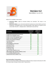
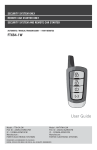
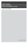
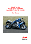
Plug&Play kit
Yamaha R1 2004/2005/2006 – R6 2004/2005
User manual
MXL Plug&Play kit for Yamaha R1 2004/2005/2006 – R6 2004/2005/
User manual
Release 1.01
INDEX
Introduction ........................................................................................................................ 3 Chapter 1 – Plug&Play kit composition ........................................................................... 4 1.1 – Part Numbers ...................................................................................................................................... 6 Chapter 2 – Plug&Play kit installation.............................................................................. 7 Chapter 3 – MXL and Yamaha connectors pinout .......................................................... 8 3.1 – MXL and Yamaha R1 2004/05/2006 AMP connectors pinout ......................................................... 8 3.2 – MXL and Yamaha R6 2004/2005 AMP connectors pinout .............................................................. 9 Chapter 4 – First start up and working mode ................................................................ 10 4.1 – Running mode .................................................................................................................................. 10 4.1.1 – Error codes in “Running mode”................................................................................................... 12 4.2 – Setting mode..................................................................................................................................... 13 4.2.1 – Setting mode with stock ECU ..................................................................................................... 13 4.2.2 – Setting mode with YEC ECU kit .................................................................................................. 14 4.3 – Diagnostic mode ..................................................................................................... 17 Chapter 5 – Calibration, gear calculation, configuration, data download and analysis
........................................................................................................................................... 19 Appendix – Wirings and pinout ...................................................................................... 20 1
www.aim-sportline.com
MXL Plug&Play kit for Yamaha R1 2004/2005/2006 – R6 2004/2005/
User manual
Release 1.01
Presentation
AIM: world leader in data acquisition for racing applications.
Established in 1976, AIM is today a world leader producer of high performances
instruments for racing applications: dashes, loggers, digital displays, lap timers.
AIM established new standards in a lot of motorsports: from kart to bikes, Dragster, and
even snowmobiles!
AIM products merges the functionalities of traditional tachometers: RPM indicators,
temperature, pressure and lap timers, with compact, high performing and friendly using
units. Different products for different applications with a shared characteristics: the great
innovation.
Each AIM system is designed, developed and tested by its technicians. The Research and
development team is made of electronics and mechanicals engineers, physics and other
specialists that develop firmware, software, hardware and the related documentation. Our
reputation is build on quality products, innovative technologies and on the steady
engagement of customer support.
2
www.aim-sportline.com
MXL Plug&Play kit for Yamaha R1 2004/2005/2006 – R6 2004/2005/
User manual
Release 1.01
0
Introduction
MXL Plug&Play kit for Yamaha R1/R6 is the dash (with data acquisition in Pista version)
designed and developed for an easy and quick installation: with the minimum effort it will
be possible to connect directly to the bike ECU and visualize (with no need of additional
sensors):
•
•
•
•
RPM
Speed
Water temperature
Air temperature
Through the bike stock sensor it will be possible to sample:
•
•
•
•
•
•
Oil level
Fuel level
Turning lights signal
High beam signal
Neutral signal)
Battery charge level
MXL, like the stock dash is powered by the bike master switch.
MXL Strada, Pista kits for Yamaha here described have been developed for the following
bike models:
Model
Year 2004
Year 2005
Year 2006
R1
9
9
9
R6
9
9
z
9 = supported
z = non supported
Note: thanks to the infrared transmitter/receiver (included in kit MXL Pista kit, optional to
MXL Strada kit), lap times will be shown/recorded. MXL Pista, moreover, allows to
manage and record data coming from 5 external configurable channels (potentiometers
suspensions, throttle sensor, brake pressure sensor, etc…).
MXL Plug&Play for Yamaha R1 2004/2005/2006 and Yamaha R6 2004/2005 has three
different operating mode:
• Running mode: is the standard mode that shows and, if connected to an MXL
Pista records, data out coming from the engine and diagnosis codes;
• Setting mode: this mode allows to set some engine parameters. Setting mode
allows to modify the ECU mapping.
• Diagnostic mode: this mode allows to manage ECU problems and errors.
For what not expressly explained in this tutorial refer to MXL and/or Race Studio
Configuration user manuals.
3
www.aim-sportline.com
MXL Plug&Play kit for Yamaha R1 2004/2005/2006 – R6 2004/2005/
User manual
Release 1.01
1
Chapter 1 – Plug&Play kit composition
Plug&Play kits for Yamaha bikes changes according to the chosen MXL model and to the
bike year of production. In the above image kit components are numbered for more clarity.
MXL Strada Plug&Play kit for Yamaha R1 2004/2005/2006 and Yamaha R6 2004/2005:
N.1 – MXL Strada (1);
N.1 – 12 pins AMP cable for MXL Strada (2);
N.1 – Yamaha bracket kit (3) made up of:
n°1 – bracket;
n°3 – washers;
n°4 – M4*8 Phillips recess screws;
n°3 –M5*18 Phillips recess screws;
N.1 – USB Cable (4)
N.1 – Race Studio 2 Software CD (5)
This manual + MXL user manual MXL (6).
Note: before installing the kit please verify that it contains all specified items.
4
www.aim-sportline.com
MXL Plug&Play kit for Yamaha R1 2004/2005/2006 – R6 2004/2005/
User manual
Release 1.01
MXL Pista Plug&Play kit for Yamaha R1 2004/2005/2006 and Yamaha R6 2004/2005:
N.1 – MXL Pista (1);
N.1 – 12 pins AMP cable for MXL Pista (2);
N.1 – Infrared receiver with 90 cm cable (3);
N.1 – Infrared transmitter (4);
N.1 – Transmitter power cable (5);
N.1 – Yamaha bracket kit (6) made up of:
n°1 – bracket;
n°3 – washers;
n°4 – M4*8 Phillips recess screws;
n°3 – M5*18 Phillips recess screws;
N.1 – USB Cable (7);
N.1 – Race Studio 2 Software CD (8);
This manual + MXL user manual (9).
Note: before installing the kit please verify that it contains all specified items.
5
www.aim-sportline.com
MXL Plug&Play kit for Yamaha R1 2004/2005/2006 – R6 2004/2005/
User manual
Release 1.01
10
1.1 – Part Numbers
MXL Strada Plug&Play kit for Yamaha R1 04/05/06: part number X16MXLSYR1407;
MXL Strada Plug&Play kit for Yamaha R6 04/05: part number X16MXLSYR6450;
MXL Pista Plug&Play kit for Yamaha R1 04/05/06: part number X16MXLCYR1407;
MXL Pista Plug&Play kit for Yamaha R6 04/05: part number X16MXLCYR6450.
Optional to all MXL Strada for Yamaha kits:
Infrared receiver: part number X41RX12090;
Infrared transmitter: part number X02TXKMA01;
Transmitter power cable: part number: V02POWTX0;
Spare parts:
Yamaha R1 2004/2005/06 and Yamaha R6 2004/2005 bracket kit: DNKTSTMXLY
12 pin AMP cable for MXL Strada: V02.554.350
12 pin AMP cable for MXL Pista: V02.554.340
6
www.aim-sportline.com
MXL Plug&Play kit for Yamaha R1 2004/2005/2006 – R6 2004/2005/
User manual
Release 1.01
2
Chapter 2 – Plug&Play kit installation
MXL Plug&Play kit for Yamaha R1/R6 has been expressly designed to guarantee
maximum installation easiness.
Please note: this kit has been expressly tested to guarantee total compatibility with
a stock bike completely corresponding to the one sold by the manufacturer. The
only compatible variation is the original YEK (Yamaha Engineering Corporation) kit.
Through the four fixing points on the product rear it is possible to substitute the original
dash in an easy and quick way with no need of bending, cutting or drilling anything: each
component is “Plug&Play”.
The system is to be connected to the high beam chassis using the bracket included in the
kit. This last is in black anodised aluminium, light weight and mechanically resistant.
GENERAL NOTES – Read these notes before installing the kit.
•
•
•
•
Do not cut any cable: the wirings included in the kit are Plug&Play;
be careful not to damage the stock connectors while plugging/unplugging them;
do not install the system when the engine is hot;
be careful not to lose screws and washers.
After having removed the stock dash:
• fix MXL to the bracket using the 4 supports highlighted in the below image;
• connect the wiring to the two connectors as explained in the below image.
7
www.aim-sportline.com
MXL Plug&Play kit for Yamaha R1 2004/2005/2006 – R6 2004/2005/
User manual
Release 1.01
3
Chapter 3 – MXL and Yamaha connectors pinout
Yamaha R1 and R6 bikes are equipped with a 16 pins AMP female connector.
8
3.1 – MXL and Yamaha R1 2004/05/2006 AMP connectors pinout
The below image shows MXL AMP connectors and the related pinout.
MXL AMP 12 pins male connector pinout
(“A”)
1A
Analog channel 10 (free)
MXL AMP 16 pins male connector pinout
(“B”)
+Vb
1B
2A
+Vb
2B
+Vb EXT
3A
GND
3B
GND
4A
Lap (optical)
4B
not used
5A
+Vref
5B
not used
6A
GND
6B
Linea K
7A
Analog channel 6 (free)
7B
oil level
8A
Analog channel 5 (free)
8B
RPM
9A
Analog channel 7 (free)
9B
+Vb
10A
Analog channel 9 (free)
10B
Hi-beam
11A
+Vref
11B
Turning lights
12A
GND
12B
Fuel
13B
Turning lights
14B
P1
15B
P2
16B
Neutral
Here below is shown 16 pin AMP female connector installed on Yamaha bike with cable
colours.
8
www.aim-sportline.com
MXL Plug&Play kit for Yamaha R1 2004/2005/2006 – R6 2004/2005/
User manual
Release 1.01
11
3.2 – MXL and Yamaha R6 2004/2005 AMP connectors pinout
The image here below shows MXL AMP connectors and the related pinout.
MXL AMP 12 pins male connector pinout
(“A”)
1A
Analog channel 10 (free)
MXL AMP 16 pins male connector pinout
(“B”)
RPM
1B
2A
+Vb
2B
Oil level
3A
GND
3B
not used
4A
Lap (optical)
4B
not used
5A
+Vref
5B
K line
6A
GND
6B
not used
7A
Analog channel 6 (free)
7B
GND
8A
Analog channel 5 (free)
8B
+Vb
9A
Analog channel 7 (free)
9B
+Vb
10A
Analog channel 9 (free)
10B
Turning lights
11A
+Vref
11B
Turning lights
12A
GND
12B
Hi-beam
13B
Neutral
14B
not used
15B
Fuel
16B
+Vb ext
Here below is shown 16 pin AMP female connector installed on Yamaha bike with cable
colours.
9
www.aim-sportline.com
MXL Plug&Play kit for Yamaha R1 2004/2005/2006 – R6 2004/2005/
User manual
Release 1.01
4
Chapter 4 – First start up and working mode
MXL Plug&Play kit for Yamaha R1/R6 can be installed on stock bikes and on bikes
equipped with original YEC (Yamaha Engineering Corporation) kit. Once the bike powered
on, MXL automatically recognizes and shows on the display the kind of ECU installed.
Supported ECUs are:
• Standard ECU (stock): the display shows “ECU MODEL STD” (image below on the
left);
• YEC kit (YEC ECU): the display shows “ECU MODEL KIT” (image below on the
right).
9
4.1 – Running mode
After ECU recognition, MXL starts working in “Running mode” and shows and manages,
as default settings, different information according on MXL model.
MXL STRADA
RPM 1
Rear speed wheel
Water temperature
Air temperature
Oil pressure
Fuel level alarm
Turning lights
High beam
Engaged gear (neutral included)
Yamaha error code
1
from ECU
from ECU
from ECU
from ECU
from sensors
from sensors
from sensors
from sensors
automatically calculated
from ECU
Shown
Shown
Shown + alarm LED
Shown + alarm LED
alarm LED
alarm LED
alarm LED
alarm LED
Shown
Available 2
RPM data can be sampled both by the bike ECU and by a stock sensor. To use the data coming from the
ECU set “RPM” box in MXL system configuration layer on “ECU”; to use the data coming from the stock
sensor set “RPM” box in MXL system configuration layer on “AIM sensor”. Refer to Race Studio
Configuration user manual for further information concerning MXL configuration. In case a deep analysis of
RPM channel is wished use data coming from the stock sensor (set “AIM sensor”) whose sampling
frequency is higher.
2
Yamaha_ERR channel is not shown by the default configuration. To see it on MXL display configure the
logger using Race Studio Configuration software. Refer to Race Studio Configuration user manual for
further information concerning MXL channels configuration.
10
www.aim-sportline.com
MXL Plug&Play kit for Yamaha R1 2004/2005/2006 – R6 2004/2005/
User manual
Release 1.01
MXL PISTA
RPM 3
Rear wheel speed
Water temperature
Air temperature
Oil pressure
Fuel level alarm
Turning lights
High beam
Engaged gear (neutral included)
Yamaha error codes
3
from ECU
from ECU
from ECU
from ECU
from sensors
from sensors
from sensors
from sensors
internally calculated
from ECU
Shown and recorded
Shown and recorded
Shown and recorded+alarm LED
Shown and recorded+alarm LED
alarm LED
alarm LED
alarm LED
alarm LED
Shown and recorded
Available 4
RPM data can be sampled both by the bike ECU and by a stock sensor. To use the data coming from the
ECU set “RPM” box in MXL system configuration layer on “ECU”; to use the data coming from the stock
sensor set “RPM” box in MXL system configuration layer on “AIM sensor”. Refer to Race Studio
Configuration user manual for further information concerning MXL configuration. In case a deep analysis of
RPM channel is wished use data coming from the stock sensor (set “AIM sensor”) whose sampling
frequency is higher.
4
Yamaha_ERR channel is not shown by the default configuration. To see it on MXL display configure the
logger using Race Studio Configuration software. Refer to Race Studio Configuration user manual for
further information concerning MXL channels configuration.
11
www.aim-sportline.com
MXL Plug&Play kit for Yamaha R1 2004/2005/2006 – R6 2004/2005/
User manual
Release 1.01
14
4.1.1 – Error codes in “Running mode”
Yamaha bikes have a diagnostic feature that shows error codes.
Here below are shown “Running Mode” error codes and the related meaning.
11
12
13,14
15,16
17,18
19
20
21
22
23
30,41
33
34
35
36
42
43,46
47
48
50
Camshaft pick up sensor problem
Crankshaft pick up sensor problem
Air pressure sensor problem
TPS sensor problem
Engine valve EXUP sensor problem
Stock bike sensor problem
Air pressure sensor problem
Water temperature sensor problem
Air temperature sensor problem
Air pressure sensor problem
Over turn sensor problem
Cylinder#1 ignition problem
Cylinder#2 ignition problem
Cylinder #3 ignition problem
Cylinder #4 ignition problem
Speed sensor or neutral (N) sensor problem
Injection system problem
EXUP valve position sensor problem
EXUP valve servo sensor problem
ECU internal problem
Warning: always refer to Yamaha and YEC official documentation for a complete
description of the errors.
In case diagnostic function detects more errors YAMAHA_ERR channel shows
error codes in sequence.
12
www.aim-sportline.com
MXL Plug&Play kit for Yamaha R1 2004/2005/2006 – R6 2004/2005/
User manual
Release 1.01
12
4.2 – Setting mode
“Setting mode” allows to modify some ECU map settings. They changes depending on if
it’s a stock ECU or an YEK kit.
Powering on MXL it starts in “Running Mode”: press “MENU/<<” and “VIEW/QUIT” at a
time to enter setting mode. The display shows “DIAG SETUP” message as here below.
Confirm pressing “OK/MEM”.
The display shows settable parameters in different pages. Use “>>”/”<<” buttons to scroll
the pages. Once reached the page to be set press “MEM/OK” to enter that page setting,
use “>>”/”<<” buttons to modify the settings and press again “MEM/OK” to save the new
settings ad exit. In case no modification has been made but the page has been entered it
is anyway necessary to press again “MEM/OK” to exit the page.
13
4.2.1 – Setting mode with stock ECU
In case the bike has a stock ECU it is only possible to change each cylinder injection
times (and consequently CO value). This setting can be made with the engine on or off.
The below table shows settable parameters.
PAGE
CO CYLINDER 1
CO CYLINDER 2
CO CYLINDER 3
CO CYLINDER 4
DESCRIPTION
Modifies first cylinder CO value (the
higher is the value the richer is the
mixture).
Modifies second cylinder CO value (the
higher is the value the richer is the
mixture).
Modifies third cylinder CO value (the
higher is the value the richer is the
mixture).
Modifies fourth cylinder CO value (the
higher is the value the richer is the
mixture).
VALUE
Allowed values are between
-128 and +127. Default
value is 0.
Refer to Yamaha technical manual for further information.
To exit setup mode recycle power on the bike.
13
www.aim-sportline.com
MXL Plug&Play kit for Yamaha R1 2004/2005/2006 – R6 2004/2005/
User manual
Release 1.01
15
4.2.2 – Setting mode with YEC ECU kit
In case of a bike equipped with ECU YEC kit it is possible to modify both injection and
ignition parameters. It is also always possible to come back to the default configuration. As
shown on the injection map, it is possible to have richer or leaner air/fuel mixtures in nine
different points of the map.
In the below table characteristics of each point of the map are explained.
Map point
Characteristics
1
TPS<25 RPM<3.000
2
TPS<25 RPM>3.000
3
25≤TPS≤90 ALLRPM
4
TPS>90 RPM<9.000
5
TPS>90 9.000≤RPM≤10.000
6
TPS>90 10.000≤RPM≤11.000
7
TPS>90 11.000≤RPM≤12.000
8
TPS>90 12.000≤RPM≤13.000
9
TPS>90 RPM>13.000
Description
Value
Modifies the quantity
of fuel injected in
point “1” of the map.
Modifies the quantity
of fuel injected in
point “2” of the map.
Modifies the quantity
of fuel injected in
point “3” of the map.
Modifies the quantity
of fuel injected in
point “4” of the map.
Modifies the quantity
of fuel injected in
point “5” of the map.
Modifies the quantity
of fuel injected in
point “6” of the map.
Modifies the quantity
of fuel injected in
point “7” of the map.
Modifies the quantity
of fuel injected in
point “8” of the map.
Modifies the quantity
of fuel injected in
point “9” of the map.
Correction ±25% of
the value in the map
Correction ±25% of
the value in the map
Correction ±25% of
the value in the map
Correction ±25% of
the value in the map
Correction ±25% of
the value in the map
Correction ±25% of
the value in the map
Correction ±25% of
the value in the map
Correction ±25% of
the value in the map
Correction ±25% of
the value in the map
Growing the value the mixture will be richer.
14
www.aim-sportline.com
MXL Plug&Play kit for Yamaha R1 2004/2005/2006 – R6 2004/2005/
User manual
Release 1.01
Warning: value selected in point “4” of the map (TPS>90 RPM<9.000) is applied in
points 5,6,7,8 and 9 too. In these last pages the shown value is to be added to the
one selected in point “4” of the map.
Ex.: point “4” shows value 10%: the mixture is 10% richer in this point;
point “5” shows value 3%: the mixture is 10+3=13% richer in this point.
Ignition map is divided in 4 parts.
Parameters can be modified in three points of the map as explained in the table here
below.
Map point
5
Characteristics
2
Advance 5 TPS<25
3
Advance 5 25≤TPS≤90
4
Advance 5 TPS>90
Description
Changes
timing in
the map.
Changes
timing in
the map.
Changes
timing in
the map.
Value
the ignition Correction
between
point “2” of +15° and -15° of the
map value.
the ignition Correction
between
point “3” of +15° and -15° of the
map value.
the ignition Correction
between
point “4” of +15° and -15° of the
map value.
Ignition advance
15
www.aim-sportline.com
MXL Plug&Play kit for Yamaha R1 2004/2005/2006 – R6 2004/2005/
User manual
Release 1.01
It is recommended to always refer to Yamaha YEC kit user manual to better take
advantage from this fonctionality.
ECU kit offers two other possibilities to modify parameters.
Page
INJN COR TO SPEED
Description
Value
Modifies the quantity if 20 correction possibilities (+10/injected mixture according 10);
to the vehicle speed.
+10 multiplies by two the default
parameter;
-10 avoid any correction;
0 uses the default parameter;
DEFAULT VALUES SET
Each level is a 10% increment (or
so) compared to the correction
factor the ECU already uses.
Shows the number of Number of modified parameters.
modified
parameters
(injection and ignition).
Modifications can be
cancelled.
After having shown the number of modified parameters it is possible to come back
to default settings pressing “>>”/”<<” and then “MEM/OK”. Led 4 starts blinking and
default parameters are restored.
16
www.aim-sportline.com
MXL Plug&Play kit for Yamaha R1 2004/2005/2006 – R6 2004/2005/
User manual
Release 1.01
5
4.3 – Diagnostic mode
It allows to monitor the behaviour of sensors and signals out coming from the ECU. It is
possible to switch from Running mode to diagnostic mode when the engine is off.
To enter Diagnostic Mode from Running Mode press first “MENU/<<” and “VIEW/QUIT” at
one time and then “MENU/<<” e “>>”.Diagnostic mode will show information concerning
different sensors in different pages. Use “MENU/<<” and “>>” to scroll through the pages.
The table here below shows the pages.
Page
THROTTLE SENSOR
Description
Shown data
Master throttle angle
Valve open angle (from 0° to
125°).
ATMO PRESSURE
Atmospheric pressure Atmospheric pressure in Kpa.
INTAKE PRESSURE
Intake air pressure.
AirBox pressure in Kpa.
INTAKE TEMP
Intake air temperature. Intake air temperature in °C.
WATER TEMP
Water temperature
Water temperature in °C
VEHICLE SPEED
Vehicle speed. Shows Reads pulses form 0 to 99.
incremental number of
pulses read by the
sensor.
OVERTURN SENSOR
Value read by the anti- Voltage value*10 (from 0 to 50)
overturn sensor.
BATTERY VOLTAGE
Battery voltage
Battery voltage
SWITCH (STOCK BIKE)
Switch (stock)
1 = OFF (stock on)
0 = OFF (stock off)
SWITCH (YEC KIT)
Switch (ECU kit)
1 = ON
0 = OFF
SELECT SWITCH (STOCK Neutral Switch
1 = Neutral
BIKE)
0 = Gear
SELECT SWITCH (YEC Map selection switch 1 = SB
KIT)
(kit YEC)
0 = ST
IGNITION COIL 1
When engine-off switch is selected and de-selected the
engine off switch turns the coil on 5 times (shown value is
IGNITION COIL 2
not important).
IGNITION COIL 3
IGNITION COIL 4
INJECTOR 1
When engine-off switch is selected and de-selected the
engine off switch turns the injector on 5 times (shown value
INJECTOR 2
is not important).
INJECTOR 3
INJECTOR 4
AI SOLENOID (STOCK When engine-off switch is selected and de-selected the
only)
engine off switch turns the AI Solenoid on 5 times.
MAIN RELAY
When engine-off switch is selected and de-selected the
engine off switch turns the main relay on 5 times (shown
value is not important).
FAN RELAY (STOCK only)
When engine-off switch is selected and de-selected the
engine off switch turns the fan relay on 5 times.
PROJECTOR RELAY
When engine-off switch is selected and de-selected the
engine off switch turns the projector relay on 5 times.
17
www.aim-sportline.com
MXL Plug&Play kit for Yamaha R1 2004/2005/2006 – R6 2004/2005/
User manual
Release 1.01
EXUP
SUBTHROTTLE
EXUP open angle
When
engine-off
switch is selected and
de-selected secondary
throttle
position
changes from totally
open to totally close..
ERRCODEEEPROM
Cylinder number in
(STOCK only)
case
of
ECU
EEPROM error.
ERRHAPPENED (STOCK Shows the sequence
only)
of detected errors.
ERRHAPPENEDCLR
Shows the number of
(Stock only)
detected errors. Can
be reset moving the
engine switch from
OFF to ON.
EXUP open angle in degree.
Secondary throttle position
degrees.
in
Cylinder number (from 1 to 4).
Shows 0 in case of no error.
Shows the sequence of detected
errors (range from 11 to 50)
In case of no error shows 0,
otherwise numbers from 1 to 25.
To exit “Diagnostic” mode recycle the power on both MXL and the ECU.
Warning: refer to Yamaha and YEC official documentation for a complete
description of the errors.
18
www.aim-sportline.com
MXL Plug&Play kit for Yamaha R1 2004/2005/2006 – R6 2004/2005/
User manual
Release 1.01
6
Chapter 5 – Calibration, gear calculation, configuration, data
download and analysis
MXL Strada/ Pista can show on the display the engaged gear.
At first start up MXL starts gear calibration and shows “RUNNING GEAR CAL” on the
display bottom string.
Warning
• For MXL to show engaged gear it is necessary to perform “Gear calibration
procedure”. Refer to Race Studio configuration user manual to know how to
do it.
• In case crown/pinion ratio has been changed a new calibration and a new
gear calculation is to be done.
• Refer to Race Studio Configuration user manual for further information
concerning gear sensor calibration and gear calculation.
MXL can be configured only using a PC and Race Studio 2 software (included in the kit).
To connect MXL to the PC use the proper USB cable included in the kit.
For any further information concerning Race Studio 2 software installation and
functionalities refer to the related user manual.
When a test session is over it is possible to download stored data (MXL Pista only) and
save them in the database integrated in Race Studio 2 software.
For further information concerning data download refer to Race Studio Configuration
user manual.
19
www.aim-sportline.com
MXL Plug&Play kit for Yamaha R1 2004/2005/2006 – R6 2004/2005/
User manual
Release 1.01
7
Appendix – Wirings and pinout
Rif. / Ref.
Q.tà/Q.ty
Progettato da / Designed by
L.I.
Firma / Signature
Contr. da / Ckd. by
330 mm
Lap in
Analog GND
+VB
Lap in
Lap
1
2
3
4
white
black
red
bleu
4
3
2
4
Lenght
Connection
Channel Binder Pin Cable Colour AMP 12 pins
12 pins AMP
female connector pinout
contact insertion view
7
8
12 11 10 9
Binder 719 connector table
3
2
4 pins Binder 719
female connector pinout
solder termination view
4
6
5
4
3
2
1
1 - 4*0.35 mm² cable
1
N. 1 - 4 pins
Binder 719
female connector
Data / Date
12 pins AMP
female connector
Plug&Play kit for MXL Strada Yamaha R1 2004/2005/2006 - R6 2004/2005 optical lap cable
N. rev. / Rev. N. Descrizione / Description
Material / Material
Contr. da / Ckd. by
N. articolo / Item N.
Approvato da / Approved by
Nome file / File name
Data / Date
Scala / Scale
Titolo / Title
Cavo Lap ottico MXL Strada per Plug&Play Yamaha R1 2004/2005/2006 - R6 2004/2005
N. disegno / Drawing N.
Racing Data Power
02.554.35
Rev. / Rev.
Foglio / Sheet
1 of 1
20
www.aim-sportline.com
MXL Plug&Play kit for Yamaha R1 2004/2005/2006 – R6 2004/2005/
User manual
Release 1.01
N. rev. / Rev. N. Descrizione / Description
Data / Date
Firma / Signature
Contr. da / Ckd. by
Binder 719 connectors table
Binder pin Cable colour
Channel
Connection
Lenght
1
2
3
4
white
black
n.c.
blue
8
6
Analogic input 5
Analogic GND
5
V Reference 1
1
2
3
4
white
black
n.c.
blue
7
6
Analogic input 6
Analogic GND
5
V Reference 1
1
2
3
4
white
black
n.c.
blue
9
12
Analogic input 7
analogico GND
11
V Reference 2
Ch. 9
1
2
3
4
white
black
red
blue
10
12
2
11
Analogic input 9
Analogic GND
+Vb
V Reference 2
380 mm
Ch. 5/Gyro
1
2
3
4
white
black
red
blue
1
3
2
11
Analogic input 10
Analogic GND
+Vb
V Reference 2
430 mm
Lap
1
2
3
4
white
black
red
blue
4
3
2
4
Lap in
Analogic GND
+Vb
Lap in
430 mm
Ch. 5
Ch. 6
Ch. 7
Rif. / Ref.
AMP 12 pin
Q.tà/Q.ty
Progettato da / Designed by
Material / Material
Contr. da / Ckd. by
330 mm
330 mm
380 mm
N. articolo / Item N.
Approvato da / Approved by
Nome file / File name
Data / Date
Scala / Scale
28/06/2005
L.I.
Titolo / Title
Cavo MXL Pista per kit Plug&Play Yamaha R1 2004/2005/2006 - R6 2004/2005
N. disegno / Drawing N.
Racing Data Power
Rev. / Rev.
Foglio / Sheet
2 of 2
21
www.aim-sportline.com
MXL Plug&Play kit for Yamaha R1 2004/2005/2006 – R6 2004/2005/
User manual
Release 1.01
N. rev. / Rev. N. Descrizione / Description
Data / Date
Firma / Signature
Contr. da / Ckd. by
Tabella connettori Binder 719
Pin Binder Colore cavo
Canale
Connessione
Lunghezza
1
2
3
4
Bianco
nero
n.c.
blu
8
6
Analog input 5
Analog GND
5
V reference 1
1
2
3
4
Bianco
nero
n.c.
blu
7
6
Analog input 6
Analog GND
5
V reference 1
1
2
3
4
Bianco
nero
n.c.
blu
9
12
Analog input 7
Analog GND
11
V reference 2
Ch. 9
1
2
3
4
Bianco
nero
rosso
blu
10
12
2
11
Analog input 9
Analog GND
+ VB
V reference 2
380 mm
Ch. 10 / Gyro
1
2
3
4
Bianco
nero
rosso
blu
1
3
2
11
Analog input 10
Analog GND
+ VB
V reference 2
430 mm
Lap
1
2
3
4
Bianco
nero
rosso
blu
4
3
2
4
Lap in
Analog GND
+ VB
Lap in
430 mm
Ch. 5
Ch. 6
Ch. 7
Rif. / Ref.
Pin AMP 12
Q.tà/Q.ty
Progettato da / Designed by
Material / Material
Contr. da / Ckd. by
330 mm
330 mm
380 mm
N. articolo / Item N.
Approvato da / Approved by
Nome file / File name
Data / Date
Scala / Scale
Titolo / Title
Cavo MXL Pista per Plug&Play Yamaha R1 2007/2008 - R6 2006/2007/2008
N. disegno / Drawing N.
Racing Data Power
Rev. / Rev.
04.554.34
Foglio / Sheet
2 di 2
22
www.aim-sportline.com