1
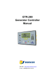
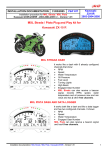
MXL P&P GSX–R K5
User Manual
Release 1.07
Kit Plug&Play – Suzuki GSX-R K5
GSX-R 600 2006/2007
GSX-R 750 2006/2007
GSX-R 1000 2005/2006
User Manual
www.aim-sportline.com
1
SUMMARY
Introduction..................................................................................................................... 3
1 – Plug&Play kit content ............................................................................................... 4
1.1 – Part Numbers (see also appendix “A”) ..........................................................................................6
2 – Plug&Play kit installation for MXL Strada wiring code 04.554.55 and MXL Pista
wiring code 04.554.54 ..................................................................................................... 7
2.1 – Removing the lateral mirrors and fairings and the front fairing. ................................................8
2.2 – Removing the stock dash, unplugging the stock connectors.....................................................8
2.3 – Milling the chassis that supports the stock dash.........................................................................9
2.4 – Assembling the kit ...........................................................................................................................9
2.5 – Connecting the cables .....................................................................................................................9
2.6 – Installing the wiring........................................................................................................................11
2.7 – Installing the TPS cable (included in the kit for MXL Pista).......................................................12
3 – Plug&Play kit installation for MXL Strada wiring code 04.554.14 and MXL Pista
wiring code 04.554.13 ................................................................................................... 13
3.1 – Removing the lateral mirrors and fairings and the front fairing. ..............................................14
3.2 – Remove the bike seat and the fuel tank.......................................................................................14
3.3 – Removing the stock dash, unplugging the connectors .............................................................14
3.4 – Milling the chassis that supports the stock dash.......................................................................16
3.5 – Assembling the kit .........................................................................................................................16
3.6 – Connecting the cables ...................................................................................................................16
3.7 – Installing TPS cable (included in the kit for MXL Pista) .............................................................18
4 – MXL inputs .............................................................................................................. 19
5 – MXL Suzuki GSX-R firmware ................................................................................. 20
6 – Suzuki GSX-R kits configuration: MXL Strada wiring code 04.554.55 and MXL
Pista wiring code 04.554.54. ........................................................................................ 21
7 – Suzuki GSX-R kits configuration: MXL Strada wiring code 04.554.14 and MXL
Pista wiring code 04.554.13 ......................................................................................... 27
7.1 – Gear Calibration .............................................................................................................................33
7.1.1 – Saving the configuration with calibrated gears .........................................................................35
8 – Equivalent circumference compute ...................................................................... 36
9 – TPS Sensor configuration...................................................................................... 37
10 – Channels................................................................................................................ 41
11 – Data download and analysis................................................................................ 43
12 – MXL expansions.................................................................................................... 44
Appendix “A” – Suzuki GSX-R K5 wiring for MXL Strada with code 04.554.55 and
MXL Pista with code 04.554.54 .................................................................................... 45
Appendix “B” – Suzuki GSX-R K5 wiring for MXL Strada with code 04.554.14 and
MXL Pista with code 04.554.13 .................................................................................... 49
Appendix “C” –TPS cable for all MXL kits code 04.550.69........................................ 55
MXL P&P GSX–R K5
User Manual
Release 1.07
PRESENTATION
AIM: a world leader in data acquisition for racing applications.
Established in 1976, nowadays AIM is a world leader in producing high performing
loggers for racing application: dashboards, data loggers, digital displays, lap timers.
AIM established new standards in a lot of motor sports: from karts to car, bikes,
dragsters, Formula 1 Boat, offshore and even snowboards!
AIM products merges the functionalities of traditional tachometers, RPM, temperature
and pressure indicators and lap timers with compact units, high performing and easy to
use. Different products for different applications but with a shared characteristics: the
great innovation.
Each AIM system is completely designed, realised and tested by its technicians. The
Research and Development board is made of Electronic and mechanic engineers,
physics and other specialists that develop software, firmware and the related
documentation. Our reputation is build on quality products, innovative technologies and
on the steady engagement in customer support.
www.aim-sportline.com
2
MXL P&P GSX–R K5
User Manual
Release 1.07
0
Introduction
MXL Plug&Play kit for Suzuki GSX-R K5 is the dashboard, with data acquisition in Pista
version, designed for an easy and quick installation: with the minimum effort it will be
possible to connect directly to the bike ECU and show - without additional sensors and
depending on the model:
MXL Strada
•
•
•
•
•
•
•
•
•
MXL Pista
•
•
•
•
•
•
•
RPM
Speed
Water temperature
Oil pressure Alarm
Fuel level alarm
Turning Lights
High Beam ON/OFF
Engaged gear
4 free channels
RPM
Speed
Water temperature
Oil pressure alarm
Engaged gear
Lateral acceleration
6 free channels
The logger, like the stock dashboard, is powered by the bike master switch.
MXL Strada/MXL Pista kits for Suzuki GSX-R K5 have been developed for the following
bike models:
Displacement
Year 2005
Year 2006
Year 2007
600
See K3 Manual
9
9
750
See K3 Manual
9
9
1000
9
9
See K7 manual
9 = supported.
Note: thanks to the infrared transmitter/receiver (included in MXL Pista kit, optional to
MXL Strada kit), it is possible to sample/record lap times.
For anything not expressly explained in this user manual, please refer to MXL or to Race
Studio Configuration user manual.
WARNING: the information concerning installation and configuration of MXL
Strada/MXL Pista Plug&Play kits for Suzuki GSX-R K5 included in this user manual
distinguish the kits depending on their wiring codes. Kit identified by 04.554.54
and 04.554.55 wiring codes are currently produced and sold while kits identified by
04.554.13 and 04.554.14 wiring codes are not produced and sold anymore: these
instructions have an only explicative function. This means that any kit bought after
the publishing of this user manual, release 1.07 or later, includes a wiring whose
identification code can only be 04.554.54 or a 04.554.55.
www.aim-sportline.com
3
MXL P&P GSX–R K5
User Manual
Release 1.07
1
1 – Plug&Play kit content
The composition of Plug&Play kits for Suzuki GSX-R K5 varies depending on the chosen
MXL version and on the bike production year. Each kit includes only some of the items
showed in the figure here above, numbered to be more clear.
MXL Strada kit
N.1 – MXL Strada (1)
N.1 – Wiring for MXL Strada Plug&Play GSX-R K5/K7 (2)
N.1 – USB cable for MXL (5)
N.1 – Accessories/optional leaflet (8)
N.1 – Race Studio 2 Software CD (9)
N.1 – Bracket kit (10), including:
1 – MXL bracket
2 – Spacing collars for Suxuki GSX-R
4 – M4*8 Phillips recess cup head screws
2 – M5*20 Phillips recess cup head screws
1 – Black EPDM washer
2 – M5 washer
www.aim-sportline.com
4
MXL P&P GSX–R K5
User Manual
Release 1.07
MXL Pista kit
N.1 – MXL Pista (1)
N.1 – Wiring for MXL Pista Plug&Play GSX-R K5/K7 (2)
N.1 – Infrared transmitter (3)
N.1 – Infrared receiver (4)
N.1 – Transmitter Power cable (6)
N.1 – TPS – throttle position sensor – cable (7)
N.1 – USB cable for MXL (5)
N.1 – Accessories/optional leaflet (8)
N.1 – Race Studio 2 Software CD (9)
N.1 – Bracket kit (10), including:
1 – MXL bracket
2 – Spacing collars for Suxuki GSX-R
4 – M4*8 Phillips recess cup head screws
2 – M5*20 Phillips recess cup head screws
1 – Black EPDM washer
2 – M5 washer
www.aim-sportline.com
5
MXL P&P GSX–R K5
User Manual
Release 1.07
Universal kit (for customers that already own an MXL Strada/Pista):
N.1 – Wiring for MXL Strada/MXL Pista Plug&Play GSX-R K5/K7 (2)
N.1 – Bracket kit (10), including:
1 – MXL bracket
2 – Spacing collars for Suzuki GSX-R
4 – M4*8 Phillips recess cup head screws
2 – M5*20 Phillips recess cup head screws
1 – Black EPDM washer
2 – M5 washer
Optional to MXL Strada kit:
N.1 – Infrared transmitter (3)
N.1 – Infrared receiver (4)
N.1 – Transmitter power cable (6)
N.1 – TPS – throttle position sensor – cable (7)
Note: before installing the kit it is suggested to check that the kits contains all specified
items.
16
1.1 – Part Numbers (see also appendix “A”)
Plug&Play kit MXL Strada for Suzuki GSX-R600/750 K5: code: X16MXLSGS0567
(CAN connection and analog channels; technical drawing nr. 04.554.55 – f1/f2).
Plug&Play kit MXL Strada for Suzuki GSX-R1000 K5: code: X16MXLSGS5610 (CAN
connection and analog channels; technical drawing nr. 04.554.55 – f1/f2).
Universal kit MXL Strada Suzuki GSX-R600/750/1000 K5 (wiring+bracket) codes:
V02554550K5+DNKTSTMXLK5 (to transform an MXL Strada in a Suzuki GSX-R K5
application; technical drawing 04.554.55 f1/f2).
Plug&Play kit MXL Pista for Suzuki GSX-R600/750 K5: code: X16MXLCGS0567 (CAN
connection and analog channels; technical drawing nr. 04.554.54 – f1/f2).
Plug&Play kit MXL Pista for Suzuki GSX-R1000 K5: code: X16MXLCGS5610 (CAN
connection and analog channels; technical drawing nr. 04.554.54 – f1/f2).
Universal kit MXL Pista Suzuki GSX-R600/750/1000 K5 (wiring+bracket) codes:
V02554540K5+DNKTSTMXLK5 (to transform an MXL Strada in a Suzuki GSX-R K5
application; technical drawing 04.554.54 f1/f2).
Optional to MXL Strada Suzuki GSX-R600/750/1000 K5 Plug&Play kit:
Infrared transmitter with 90 cm cable: code: X41RX12090
Infrared transmitter: code: X02TXKMA01
Transmitter power cable: code: V02POWTX0
TPS – Throttle Position Sensor – cable: code: V02550690.
www.aim-sportline.com
6
MXL P&P GSX–R K5
User Manual
Release 1.07
2
2 – Plug&Play kit installation for MXL Strada wiring code
04.554.55 and MXL Pista wiring code 04.554.54
The instructions included in this user manual are intended for an MXL Strada/MXL Pista
with firmware version 14.86.33 or later and Race Studio 2 release 2.30.04 or later.
Suzuki GSX-R K5 Plug&Play wiring has been expressly designed and developed to be
absolutely easy to install.
Warning: this kit has been tested to be absolutely compatible with a bike identical
to the stock one sold by the manufacturer.
Thanks to the back fixing points of MXL it is possible to replace the stock dash in an easy
and quick way.
The logger has to be connected to the chassis of the stock front screen using the bracket
included in the kit. The bracket is in black anodized aluminium light weight and
mechanically resistant.
GENERAL NOTES – Read these notes before installing the system.
•
•
•
•
•
•
Do not cut any cable: the cable supplied with the kit is Plug&Play.
Pay attention not to damage the stock connectors while plugging/unplugging
them. In the following pages it’s described how to correctly manage them.
Do not install the system when the engine is hot. The stock connectors are
near to the engine and there is burning risk.
The space under the fuel tank is quite small: pay attention while demounting/
mounting it.
Pay attention not to loose screws and washers.
Pay attention not to damage the fairing while demounting/mounting them.
www.aim-sportline.com
7
MXL P&P GSX–R K5
User Manual
Release 1.07
25
2.1 – Removing the lateral mirrors and fairings and the front fairing.
To disconnect the stock dash and install MXL on Suzuki GSX-R K5 bike it is necessary
to remove:
• front screen
• lateral mirrors
• lateral fairings
• fuel tank
Note: refer to the bike user manual for further information concerning this step.
17
2.2 – Removing the stock dash, unplugging the stock connectors
The second installation step is removing the stock dash and disconnecting the stock
connectors.
The stock dash is fixed through 3 fixing points red circled in Figures 1a and 1b.
Figure 1a: stock dash fixing points
rear view.
Figure 1b: particular of fixing point labelled “3”
front view.
Once the stock dash has been removed,
unplug the 16 pins AMP bike stock
connector from the dash back.
Remove the cover as shown in Figure 2
and pull down the tongue (highlighted in
red): unthread the dash connector.
Figure 2: unplugging the 16 pins AMP connector
from the stock dash.
www.aim-sportline.com
8
MXL P&P GSX–R K5
User Manual
Release 1.07
26
2.3 – Milling the chassis that supports the stock dash
The lap connector is under the chassis that
supports the stock dash. This is why the
third installation step is milling a part of this
chassis to connect “Lap” cable to the stock
connector. In figure 3 the part of the
chassis to be milled is highlighted (2). Pay
attention not to damage the anti-vibration
mounting (1) while milling the chassis.
Figure 3: chassis to be milled (2) and anti-vibration
mounting (1).
18
2.4 – Assembling the kit
The fourth installation step is assembling
the kit. It has four anti-vibration mounting
already mounted on the back of MXL.
Install MXL on its bracket and fix this last
one in correspondence of the four antivibration mountings using the Phillips
recess cup head screws and the washers
included in the kit.
Figure 4: anti-vibration mounting particular.
Figure 5 shows MXL correctly assembled
with bracket and washers (rear view).
Figure 5: MXL and bracket – rear view.
19
2.5 – Connecting the cables
The fifth installation step is installing the
wiring supplied with the kit.
The wiring is wrapped in a plaited
protective covering. Bent it and let it pass
on the bike right side.
Figure 6: wiring installation.
www.aim-sportline.com
9
MXL P&P GSX–R K5
User Manual
Release 1.07
Connect the 16 pins connector (previously
unplugged from the stock dash) to the
male connector placed in the black
aluminum box of MXL wiring as shown in
figure 7: press until you hear a click.
Use the stock dash plastic cover to make
the connection waterproof.
Figure 7: wiring connection.
Let the wiring run between the high beam
and the front fairing (figure 8).
Note: the 2 AMP connectors, the wiring
labelled “Lap” and the stock wiring (ending
with a channel interface wiring) are too big
to pass between the high beam and the
front fairing. It is suggested to insert the
wiring from above.
Figure 8: kit installation.
www.aim-sportline.com
10
MXL P&P GSX–R K5
User Manual
Release 1.07
27
2.6 – Installing the wiring
To install the wiring follow this procedure. It shows a black ground cable labelled “GND”
that needs to be directly connected to the negative pole of the bike battery, as shown in
the images below.
The cable highlighted by the arrow in
figure 14 is external to the wiring.
Figure 9: the ground black cable.
Let it run along the bike chassis, as
indicated in figure 10, until the bike
battery.
Figure 10: the ground cable runs along the chassis.
Once reached the battery connect it to the
negative pole (figure 11).
Figure 11: the connection of ground cable to the
battery negative pole.
In figure 12 the external ground cable
correctly connected to the battery negative
pole is shown.
Figure 12: ground cable correctly connected.
www.aim-sportline.com
11
MXL P&P GSX–R K5
User Manual
Release 1.07
28
2.7 – Installing the TPS cable (included in the kit for MXL Pista)
Warning: before installing this cable it is necessary to demount the bike fuel tank.
Refer to the bike user manual for further information on the subject.
Figure 13: TPS cable installation.
Unplug the original Suzuki wiring from TPS sensor and connect it to the male connector
of MXL wiring for TPS sensor (as indicated in the box of figure 13).
Connect the female connector of MXL wiring for TPS sensor to the same sensor (as
highlighted by the blue arrow).
Connect the 4 pins male plastic Binder connector to one of the free channels depending
on the model of MXL (see “Channels” chapter).
For further information concerning the configuration of the channel the TPS sensor is
installed on, refer to the related chapter of this user manual.
www.aim-sportline.com
12
MXL P&P GSX–R K5
User Manual
Release 1.07
3
3 – Plug&Play kit installation for MXL Strada wiring code
04.554.14 and MXL Pista wiring code 04.554.13
WARNING: kit whose wiring is identified by codes 04.554.13 and 04.554.14 is no
more in production and this chapter - like the one concerning the logger
configuration - has just an explicative function for customers owning this kit.
Suzuki GSX-R K5 Plug&Play wiring has been expressly designed and developed to be
absolutely easy to install.
Warning: this kit has been tested to be absolutely compatible with a bike identical
to the stock one sold by the manufacturer.
Thanks to the back fixing points of MXL it is possible to replace the stock dash in an easy
and quick way: each component is Plug&Play.
The logger has to be connected to the chassis of the stock front screen using the bracket
included in the kit. The bracket is in black anodized aluminum light weight and
mechanically resistant.
GENERAL NOTES – Read these notes before installing the system.
•
•
•
•
•
•
Do not cut any cable: the cable supplied with the kit is Plug&Play.
Pay attention not to damage the stock connectors while plugging/unplugging
them. In the following pages it’s described how to correctly manage them.
Do not install the system when the engine is hot. The stock connectors are
near to the engine and there is burning risk.
The space under the fuel tank is quite small: pay attention while demounting /
mounting it.
Pay attention not to loose screws and washers.
Pay attention not to damage the fairing while demounting/mounting them.
www.aim-sportline.com
13
MXL P&P GSX–R K5
User Manual
Release 1.07
29
3.1 – Removing the lateral mirrors and fairings and the front fairing.
To disconnect the stock dash and install MXL on Suzuki GSX-R K5 bike it is necessary
to remove:
• front screen
• lateral mirrors
• lateral fairings
• fuel tank
Note: refer to the bike user manual for further information concerning this step.
20
3.2 – Remove the bike seat and the fuel tank
To reach stock connectors (water, gear and TPS) it is necessary to remove the bike seat
and the fuel tank.
Note: refer to the bike user manual for further information concerning this subject.
21
3.3 – Removing the stock dash, unplugging the connectors
The third installation step is removing the stock dash and unplugging its connectors.
The stock dash is fixed to the bike through
three fixing points.
In figure 14 the back and the front anchor
points of the stock dash are red circled.
Figure 14: the stock dash has been removed
When the stock dash has been removed it
is needed to unplug the 16 pins AMP
connector from the same dash back side.
Remove the protective cover as shown in
figure 15 and pull down the tongue
(highlighted in red): unthread the connector
from the dash.
Figure 15: unplug the stock dash.
www.aim-sportline.com
14
MXL P&P GSX–R K5
User Manual
Release 1.07
Figure 16 shows the position of gear and
water temperature stock connectors.
For further information concerning the stock
connectors refer to figures from 17 to 19.
Figure 16: stock connectors position.
The stock gear connector is a 3 pins white
one placed on the bike left side (figure 16).
Here below male and female gear
connectors are drawn.
Note: cable colours correspond to the real
ones.
Figure 17: gear connector – particular.
How to unplug a 3 pins connector.
3 pins male and female connectors are
strictly fixed. To disconnect the male from
the female use a flat screwdriver: pull down
the tongue and unplug the connectors.
Warning: to unplug the connectors unplug
the plastic cases and not the cables, that
could disconnect seriously damaging the
wiring.
Stock water temperature connector, shown
in figure 19, is green, has 2 pins and is
placed on the left part of the engine cylinder
block of the bike. (figure 16).
Here below the stock water temperature
connector is drawn.
Note: cable colours correspond to the real
ones.
Figure 18: how to unplug a connector.
Figure 19: water temperature connector –
particular.
www.aim-sportline.com
15
MXL P&P GSX–R K5
User Manual
Release 1.07
30
3.4 – Milling the chassis that supports the stock dash
The lap connector is under the chassis that
supports the stock dash. This is why the
fourth installation step is milling a part of
this chassis to connect “Lap” cable to the
stock connector. In figure 20 the part of the
chassis to be milled (2) is highlighted. Pay
attention not to damage the anti-vibration
mounting (1) while milling the chassis.
22
Figure 20 - chassis to be milled (2) and antivibration mounting (1).
3.5 – Assembling the kit
The fifth installation step is assembling the
kit for Suzuki GSX-R. It has four antivibration mounting already installed on the
back of MXL.
Install the logger on its aluminium bracket in
correspondence of the four anti-vibration
mounting, using screws and washers
included in the kit.
Figure 21 – anti-vibration mounting particular.
Figure 22 shows MXL correctly assembled
with bracket and washers (rear view).
Figure 22 – MXL and bracket – rear view.
23
3.6 – Connecting the cables
The sixth installation step is installing the
wiring included in the kit.
The wiring is all wrapped in a plaited
protective covering. Bent it and let it run
along the bike right side.
Figure 23 – Wiring installation.
www.aim-sportline.com
16
MXL P&P GSX–R K5
User Manual
Release 1.07
Connect the 16 pins black AMP connector
(previously unplugged from the stock dash)
to the male one placed in the black
aluminum box of MXL wiring shown in
figure 24: press until you hear a click.
Use the plastic cover of the stock dash to
make the connection waterproof.
Figure 24 – wiring installation – particular of AMP
connector.
Connect male and female water and gear
connectors (these green and white
previously disconnected) to the related
connectors of MXL wiring.
Let cables labelled “Gear”, “Water Temp”
etc… run along the bike chassis as shown
in figure 25. Use plastic wrappers to fix
them to the bike stock wiring.
“Gear” and “water temperature” stock
connectors are under the fuel tank: let them
enter the engine compartment as shown in
figure 25.
Figure 25 – wirings running along the bike chassis.
Let all cables (except for “Lap” one”) run
between the high beam and the front fairing
(figure 26).
Note: the 2 AMP connectors, cable labelled
“Lap” and stock wiring (the one ending with
a black channels interface box) are too big
to pass between the high beam and the
chassis. It is suggested to insert the wiring
from above.
Figure 26 – kit installation.
www.aim-sportline.com
17
MXL P&P GSX–R K5
User Manual
Release 1.07
24
3.7 – Installing TPS cable (included in the kit for MXL Pista)
Warning: before installing this cable it is necessary to demount the bike fuel tank.
Refer to the bike user manual for further information on the subject.
Figure 27: TPS cable installation.
Unplug the original Suzuki wiring from TPS sensor and connect it to the male connector
of MXL wiring for TPS sensor (as indicated in the box of figure 27).
Connect the female connector of MXL wiring for TPS sensor to the same sensor (as
highlighted by the blue arrow).
Connect the 4 pins male plastic Binder connector to one of the free channels - depending
on the model of MXL (see “Channels” chapter).
For further information concerning the configuration of the channel the TPS sensor is
installed on, refer to the related chapter of this user manual.
www.aim-sportline.com
18
MXL P&P GSX–R K5
User Manual
Release 1.07
4
4 – MXL inputs
Thanks to interface cables included in Suzuki GSX-R K5 Plug&Play kit, data acquisition
is really easy and quick. The image below shows all inputs that allow data visualization
on MXL.
Figure 28: MXL Strada/MXL Pista: rear view.
•
•
•
•
Lap connector (1): allows lap time detection;
External expansion Modules connector (2): allows the connection with all
expansion modules that communicate through the CAN bus (GPS, lambda
probe);
AMP 12 pins female connector (3) AIM wiring supplied with the kit;
AMP 16 pins female connector (4) AIM wiring supplied with the kit.
www.aim-sportline.com
19
MXL P&P GSX–R K5
User Manual
Release 1.07
5
5 – MXL Suzuki GSX-R firmware
MXL Strada/MXL Pista for Suzuki GSX-R K5 is equipped with a special firmware version
that supplies the logger with a second virtual dashboard.
Note: MXL firmware version has to be 14.86.33 or later.
On the street the display is set on “street mode” and shows the following parameters:
•
•
•
•
•
•
Bar graph with configurable scaling: black;
RPM digital value/ battery voltage/ total and partial odometer/ date and time:
fuchsia (use VIEW/QUIT button to switch between the options).
Speed: red
Engaged gear: green.
Analog channels always on top, depending on MXL model: bleu.
Up to 4 fields shown on demand and selectable by the drop down menu of
System Configuration window of Race Studio 2. Use “>>” button to switch
between the fields.
Figure 29 – Display on street mode.
On track, passing by a switched on transmitter, the display switches automatically on
“track mode” and shows lap time in spite of odometer.
Figure 30 – Display on track mode.
Visualization mode (street/track) is set via software and stored by the logger. Default
setting is show odometer (street mode). If user sets show lap time (track mode) via
software, this setting is restored at each switch on, no matter if the bike is on track or not.
Note: for further information concerning display management and its configuration refer
to MXL and/or Race Studio Configuration user manual.
www.aim-sportline.com
20
MXL P&P GSX–R K5
User Manual
Release 1.07
6
6 – Suzuki GSX-R kits configuration: MXL Strada wiring code
04.554.55 and MXL Pista wiring code 04.554.54.
When MXL has been installed it is ready to work thanks to the default configuration. In
case a custom configuration is needed, follow these instructions.
• Run Race Studio 2 software (release 2.30.04 or later).
• Press “AIM system manager” button on the left vertical toolbar.
• Select MXL icon from the panel that appears on the right of the vertical
keyboard.
Press “new” and this window appears.
www.aim-sportline.com
21
MXL P&P GSX–R K5
User Manual
Release 1.07
Fill in the window below with:
• Data logger type: select MXL Pista (or MXL Strada) depending on the
owned logger and paying attention to select the correct displacement (600,
750 or 1000) and the correct wiring identification code.
• New configuration name: fill in a name for the new configuration.
• Vehicle name: fill in a vehicle name.
• Unit of measure: select the desired units of measure for speeds,
temperatures and pressures.
Click on “OK” to create the new configuration.
Select “Channels” layer to enter the configuration of MXL sampled channels.
www.aim-sportline.com
22
MXL P&P GSX–R K5
User Manual
Release 1.07
In case an MXL Strada is being configured this window appears:
In case an MXL Pista is being configured this window appears:
Both show the channels sampled by the logger and speed panel labelled “Speed” and
highlighted in the images above.
Note: all additional channels are disabled by default; for any information concerning their
configuration refer to Race Studio Configuration user manual.
www.aim-sportline.com
23
MXL P&P GSX–R K5
User Manual
Release 1.07
Speed panel: Suzuki GSX-R speed sensor is installed on the jackshaft that connects the
gearbox to the pinion. The number of magnets installed on this jackshaft is 4.
The wheel circumference used in this panel is an “Equivalent Circumference” computed
using this formula:
EquivCircumf =
WheelCircumf * Np
Nc
Np = pinion teeth number
Nc = Crown teeth number
Using default values computed for a Suzuki GSX-R750, the equivalent circumference
value is 747 mm (29.4 inches). Changing the pinion or the crown with one that has a
different teeth number equivalent circumference needs to be re-computed. For further
information on this computation refer to the related chapter of this user manual.
www.aim-sportline.com
24
MXL P&P GSX–R K5
User Manual
Release 1.07
It is now necessary to configure MXL display.
Select “System Configuration” layer.
The window shown here below appears. Default values differ depending on the model of
MXL selected when creating the configuration.
Set fields are: RPM, Shift lights, Speed, Lap; some alarms and the gear sensor.
www.aim-sportline.com
25
MXL P&P GSX–R K5
User Manual
Release 1.07
RPM: high scale can be set to a value included between 14000 and 16000 RPM
depending on the bike displacement.
Lap: obscuring time 8 seconds and 1 lap segment (no split times).
Shift Lights: each displacement has different threshold values, computed considering
the stock engine limiter threshold value. In case the bike engine limiter has an higher
threshold value than the stock one, default values need to be modified so that the last
red light switches on just before limiter intervention.
Default visualization is:
• ECT: water temperature; threshold value “>” (more than) 105 °C.
• OIL PRESS: oil pressure; threshold value “<” (less than) 2 bar.
• BATTERY: battery voltage; alarm threshold value “<” (less than) 13 volts.
• FUEL LEVEL: fuel level: threshold value “<” (less than) 20. This value is
expressed in percentage and corresponds to the bike reserve value (around
4.5 litres – 1 gallon).
• ODOMETER: run kilometres. This default setting changes automatically once
on the track (with infrared transmitter and receiver). The logger switches on
“show lap time” if detects a lap signal. Switching OFF/ON the logger it shows
again odometer.
Note: to modify and customize the shown channels with the related alarms, refer to Race
Studio Configuration user manual.
The configuration is now ready to be transmitted to the logger. Press “Transmit” button
on the software top keyboard.
www.aim-sportline.com
26
MXL P&P GSX–R K5
User Manual
Release 1.07
7
7 – Suzuki GSX-R kits configuration: MXL Strada wiring code
04.554.14 and MXL Pista wiring code 04.554.13
WARNING: this kit version is not produced anymore: these instructions have just
an explicative function for customers that already own the kits.
When MXL has been installed it is ready to be used thanks to the default configuration. In
case a custom one is needed, follows these instructions.
• Run Race Studio 2 software.
• Press “AIM system manager” button on the left vertical keyboard.
• Select MXL icon on the panel that appears right of the vertical keyboard.
Press “New” and this window appears:
www.aim-sportline.com
27
MXL P&P GSX–R K5
User Manual
Release 1.07
Fill in the window below with:
• Data logger type: select MXL Pista (or MXL Strada) depending on the
owned logger and paying attention to select the correct displacement (600,
750 or 1000) and the correct wiring identification code.
• New configuration name: fill in a name for the new configuration.
• Vehicle name: fill in a vehicle name.
• Unit of measure: select the desired units of measure for speeds,
temperatures and pressures.
Press “OK” to create the new configuration.
Select “Channels” layer to configure the channels sampled by MXL.
www.aim-sportline.com
28
MXL P&P GSX–R K5
User Manual
Release 1.07
In case an MXL Strada is being configured, this window appears:
In case an MXL Pista is being configured, this window appears:
Both show the channels sampled by the logger and speed panel – labelled “Speed” and
highlighted in the figures above.
Note: additional channels are disabled by default. Refer to Race Studio Configuration
user manual for further information concerning their configuration.
www.aim-sportline.com
29
MXL P&P GSX–R K5
User Manual
Release 1.07
Speed panel: Suzuki GSX-R speed sensor is installed on the jackshaft that connects the
gearbox to the pinion. The number of magnets installed on this jackshaft is 4.
The wheel circumference used in this panel is an “Equivalent Circumference” computed
using this formula:
EquivCircumf =
WheelCircumf * Np
Nc
Np = pinion teeth number
Nc = Crown teeth number
Using default values computed for a Suzuki GSX-R750, the equivalent circumference
value is 801.4 mm (31.55 inches). Changing the pinion or the crown with one that has a
different teeth number equivalent circumference needs to be re-computed. For further
information on this computation refer to the related chapter of this user manual.
www.aim-sportline.com
30
MXL P&P GSX–R K5
User Manual
Release 1.07
It is now necessary to configure MXL display.
Select “System configuration” layer:
The window below appears. Default values are different depending on the model of MXL
selected while creating the configuration.
Set fields are: RPM, Shift lights, speed, lap, some alarms and the gear sensor.
www.aim-sportline.com
31
MXL P&P GSX–R K5
User Manual
Release 1.07
RPM: high scale value is set on 14000 RPM.
Lap: obscuring time: 8 seconds and number of segments: 1 (no split times).
Shift lights: each displacement has different threshold values, computed considering the
stock engine limiter threshold value. In case the bike limiter has a threshold value higher
than the stock one, default values need to be modified so that the last red light switches
on just before limiter intervention.
Default visualization is:
• ECT: water temperature alarm threshold values: “>” (max) 90°C; “<” (min)
50°C.
• ODOMETER: run kilometres. This default setting changes automatically once
on the track (with infrared transmitter and receiver). The logger, in fact,
switches on “Show lap time” if detects a lap signal. Switching OFF/ON the
logger it shows again odometer.
Note: refer to Race Studio Configuration user manual for further information about the
modification and customization of sampled channels.
The configuration is now ready to be transmitted to MXL: press “Transmit” button on the
software top keyboard.
www.aim-sportline.com
32
MXL P&P GSX–R K5
User Manual
Release 1.07
31
7.1 – Gear Calibration
Gear calibration is the last step to finish system configuration; it is to perform only in case
the default one does not allow visualization of the correct engaged gear number and can
be done only through a PC with Microsoft Windows XP or Microsoft Window Vista 32 bit
operating system and Race Studio 2 software (included in the kit).
The logger needs to be connected to the PC using the proper USB cable included in the
kit.
Connect MXL to the PC and switch both on (firstly the PC and then MXL); run Race
Studio 2 and follow this procedure:
• press “AIM System manager” button on the left vertical keyboard and select
“MXL” on the panel that appears right of the vertical keyboard (MXL
Strada/MXL Pista Susuki GSX-R).
• press “Calibration” button on the menu bar or on the vertical keyboard
(highlighted in the figure below).
This window appears: press “calibrate” button corresponding to the sensor to calibrate (in
this case gear potentiometer).
www.aim-sportline.com
33
MXL P&P GSX–R K5
User Manual
Release 1.07
Calibration panel appears.
•
•
•
Select the higher gear number enabling the corresponding checkbox and
press “CONTINUE”.
engage one by one all gears, also with the engine off but with the ignition on
and click on “CONTINUE” after each gear, as for the instruction that appears
on the panel right to “raw value” column.
When calibration is over the window below appears. Press “END
CALIBRATION”.
www.aim-sportline.com
34
MXL P&P GSX–R K5
User Manual
Release 1.07
•
The system comes back to the previous window and shows sensor status
“calibrated” in red and “Transmit calibration” button enabled. Press it to
transmit the calibration to the logger.
Warning: the configuration transmitted to the logger is not automatically stored in
the software configurations database. This means that, once transmitted to the
logger, the configuration is not inserted in the available configurations database.
32
7.1.1 – Saving the configuration with calibrated gears
To save the new configuration with calibrated gears in Race Studio 2 configurations
database, activate “Select Configurations” layer and press “Receive” button on the top
keyboard.
The configuration of the logger connected to the PC, previously transmitted, is received,
saved as the last one on bottom of available configurations database and highlighted in
yellow.
Note: for any further information concerning Race Studio 2 installation and configuration
refer to the related user manual.
www.aim-sportline.com
35
MXL P&P GSX–R K5
User Manual
Release 1.07
8
8 – Equivalent circumference compute
The equivalent circumference can be computed using “Bike.exe” software, included in
Race Studio 2 CD, utilities folder. Browse the CD and double click on “Bike.exe” icon.
Fill in “Drive gear teeth number”.
Fill in “Driven gear teeth number”.
Select the circumference unit of measure.
Fill in the circumference value.
Press “Compute”.
The software computes the equivalent
circumference value and shows it in the
related cell (red circled here on the right).
Fill in this value in the related case of Race
Studio 2 “Channels” layer.
www.aim-sportline.com
36
MXL P&P GSX–R K5
User Manual
Release 1.07
9
9 – TPS Sensor configuration
After having installed the sensor on the bike (see the related chapter for further
information), it is necessary to calibrate it so that it samples correct data.
This procedure can be performed only using a PC with Microsoft Windows Xp or
Microsoft Windows Vista 32 bit operating system and Race Studio 2 software (included
in the kit).
The logger needs to be connected to the PC through the USB cable supplied with the kit
and switched on.
Run Race Studio 2 software and press “AIM system manager” button on the left vertical
keyboard. Select “MXL” on the panel that appears right of the vertical keyboard.
To set TPS sensor on a channel follow this procedure.
• Activate “Channels” layer.
• Select the channel where the sensor has been physically installed on.
• Enable the checkbox corresponding to it in “Enable/Disable” column.
• Set, if desired, a channel name.
• Select “Zero based potentiometer” in the drop down menu of “Sensor Type”
column.
• Set the desired unit of measure in “Unit” column
• Set high scale value (recommended 110%)
• Press “Transmit” button on the top keyboard to transmit the configuration to
the logger.
www.aim-sportline.com
37
MXL P&P GSX–R K5
User Manual
Release 1.07
When TPS sensor has been set on a channel, it needs to be calibrated. Click on
“Calibration” button on the left vertical keyboard or on the menu bar (red circled in the
figure below).
This window appears.
Click on “Calibrate” button corresponding to the sensor to calibrate (in this case “Zero
based potentiometer”).
www.aim-sportline.com
38
MXL P&P GSX–R K5
User Manual
Release 1.07
This window appears:
Follow the instruction that appears on the PC monitor.
• with the gas completely opened press “Get raw data” button corresponding to
High Position.
• with the gas in its zero position press “Get raw data” button corresponding to
Zero position.
• Match raw data with custom values to insert in “Measure” box. For example
match raw data sampled with gas completely opened with 100 value and raw
data sampled with gas closed to “0” value.
• Press “OK”
• The system comes back to the previous window.
www.aim-sportline.com
39
MXL P&P GSX–R K5
User Manual
Release 1.07
The window shows sensor status turned to “calibrated” in red and “Transmit calibration”
button enabled. Pressing it the calibration is transmitted to the logger.
Warning: the configuration with TPS sensor calibrated, once transmitted to the
logger, is not saved in Race Studio 2 configurations database. This means that to
have it stored it is necessary to receive it as previously explained.
www.aim-sportline.com
40
MXL P&P GSX–R K5
User Manual
Release 1.07
10
10 – Channels
Default channels setting of MXL Strada/MXL Pista for Suzuki GSX-R is:
MXL Strada Suzuki GSX-R K5 (wiring code 04.554.55)
Channel identification
RPM
SPD_1
Ch_1
Ch_2
Ch_3
Ch_4
Ch_5
Ch_6
Ch_7
Ch_8
LOG_TMP
BATT
ECU1
ECU2
Channel name
Engine
Speed1
Oil_Press
Fuel_level
Turning_Light
Hi_Beam
Channel_5
Channel_6
Channel_7
Channel_8
Datalogger_Temp
Battery
ECT
Gear
Function
RPM Value
Speed Value
Oil Pressure
Fuel level
Turning_Lights ON/OFF
High Beam ON/OFF
Free Channel
Free Channel
Free Channel
Free Channel
Logger internal temperature
Battery voltage
Temperature Sensor
Gear Sensor
MXL Pista Suzuki GSX-R K5 (wiring code 04.554.54)
Channel identification
RPM
SPD_1
Ch_1
Ch_2
Ch_3
Ch_4
Ch_5
Ch_6
Ch_7
Ch_8
Acc1
LOG_TMP
BATT
ECU1
ECU2
Channel name
Engine
Speed1
Oil_Press
Fuel_level
Channel_3
Channel_4
Channel_5
Channel_6
Channel_7
Channel_8
LatAcc
Datalogger_Temp
Battery
ECT
Gear
www.aim-sportline.com
Function
RPM Value
Speed Value
Oil Pressure
Fuel level
Free Channel
Free Channel
Free Channel
Free Channel
Free Channel
Free Channel
Lateral Accelerometer
Logger internal temperature
Battery voltage
Temperature Sensor
Gear Sensor
41
MXL P&P GSX–R K5
User Manual
Release 1.07
MXL Strada Suzuki GSX-R K5 (wiring code 04.554.14)
Channel identification
RPM
SPD_1
Ch_1
Ch_2
Ch_3
Ch_4
Ch_5
Ch_6
Ch_7
Ch_8
LOG_TMP
BATT
Channel name
Engine
Speed1
Water_Temp_ECT
Channel_2_free
Oil_Press_signal
Channel_4_free
Fuel_level
Turning_Light
Hi_beam
Gear_Pot
Datalogger_Temp
Battery
Function
RPM Value
Speed Value
Suzuki Water temperature
Free Channel
Oil Pressure
Free Channel
Fuel level
Turning Lights ON/OFF
High Beam ON/OFF
Calculated Gear
Logger internal temperature
Battery voltage
MXL Pista Suzuki GSX-R K5 (wiring code 04.554.13)
Channel identification
RPM
SPD_1
Ch_1
Ch_2
Ch_3
Ch_4
Ch_5
Ch_6
Ch_7
Ch_8
Acc1
LOG_TMP
BATT
Channel name
Engine
Speed1
Water_Temp
Channel_2
Channel_3
Channel_4
Channel_5
Channel_6
Channel_7
Gear
LatAcc
Datalogger_Temp
Battery
Function
RPM Value
Speed Value
Suzuki Water Temperature
Free Channel
Free Channel
Free Channel
Free Channel
Free Channel
Free Channel
Calculated Gear
Lateral Accelerometer
Logger internal temperature
Battery voltage
According to the wiring you got, free channels can be freely configured to connect
additional sensors like suspension potentiometers, brake and pressure sensors, etc.
Note: for further information concerning additional sensors installation and configuration
refer to Race Studio Configuration and to MXL user manual.
www.aim-sportline.com
42
MXL P&P GSX–R K5
User Manual
Release 1.07
11
11 – Data download and analysis
Once a test session is over it is possible to download data stored in the logger memory
and save them in a database.
Note: data download and analysis is only available on MXL Pista. For further information
on these subjects refer to the related user manuals.
www.aim-sportline.com
43
MXL P&P GSX–R K5
User Manual
Release 1.07
12
12 – MXL expansions
Thanks to the wide range of AIM products, expressly dedicated to the needs of any biker,
MXL is a modular and expandable system.
GPS Module
GPS Module allows to sample a lot of
important information: brake analysis,
information concerning the chassis,
analysis of the behaviour of the biker in
any point of the track.
This allows to view trajectories, the related
speed and evaluate driving errors.
Exporting all the information on Google
Earth® it will thereby be possible to over
impose real images to the run trajectories.
LCU-ONE CAN
LCU-ONE CAN controls and allows to
optimize the Stoichiometric ratio (Air/Fuel)
with extreme precision.
To
obtain
the
maximum
engine
performance, LCU-ONE uses a wide band
Bosch LSU 4.9 probe and can detect
punctual Lambda values in a 0.65-1.6
range.
www.aim-sportline.com
44
MXL P&P GSX–R K5
User Manual
Release 1.07
Appendix “A” – Suzuki GSX-R K5 wiring for MXL Strada with
code 04.554.55 and MXL Pista with code 04.554.54
Rif. / Ref.
Q.tà / Q.ty
Progettato da / Designed by
7
8
12 11 10 9
4 pins Binder 719
female connector pinout
Solder terminatin view
3
2
16 15 14 13 12 11 10 9
4
1
1
2
3
4
5
6
7
8
1
2
3
4
6
5
12 pin AMP
female
connector
16 pin AMP
female
connector
Materiale / Material
Contr. da / Ckd. by
Contr. da / Ckd. by
16 pins AMP female
connector pinout
Contact insertion view
Firma / Sign
N. 2 - 4 pins Binder 719
female connectors
N. 2 - 4 x 0.35 mm²
cables
N. 2 - 4 pins Binder 719
female connectors
N. 2 - 3 x 0.35 mm²
cables
N. 1 - 12 x 0.25 mm²
cable
N. 1 - 10 pins Hirose
female connector
Data / date
12 pins AMP female
connector pinout
Contact insertion view
N.rev. / Rev. N. Descrizione / Description
MXL Strada - Plug & Play Suzuki GSXR K5-K7 wiring
13
N. articolo / Item N.
Approvato da / Approved by
Nome file / File name
Data / Date
Scala / Scale
DB
Titolo / Title
MXL Strada - Plug & Play Suzuki GSXR K5-K7 wiring
N. disegno / Drawing N.
Racing Data Power
04.554.55
www.aim-sportline.com
Rev. / Rev.
Foglio / Sheet
1 di 2
45
MXL P&P GSX–R K5
User Manual
Release 1.07
N.rev. / Rev. N. Descrizione / Description
Data / date
Firma / Sign
Contr. da / Ckd. by
Binder 719 female connector table
Label
Binder pin
Cable colour
Ch. 5
1
2
3
4
White
Black
1
2
3
4
White
Black
1
2
3
4
White
Black
Red
Bleu
4 x 0.35 mm²
1
2
3
4
White
Black
Red
Bleu
4 x 0.35 mm²
Ch. 6
Ch. 7
Ch. 8
Cable type
AMP 12 pin
Length
AMP 16 pin
Connection
16
15
Analog Input 5
Analog GND
14
V Reference
13
11
Analog input 6
Analog GND
14
V Reference
12
3
Analog Input 7
Analog GND
+VB
V Reference
380 mm
Analog Input 8
Analog GND
+VB
V Reference
400 mm
3 x 0.35 mm²
Bleu
3 x 0.35 mm²
Bleu
9
6
9
7
11
2
300 mm
340 mm
10 pins Hirose female connector table
Label
Pin AMP
12 pin
Pin AMP
16 pin
2
ASG07 o
ASG05/A
Board
12
1
8
8
5
4
1
4
3
Rif. / Ref.
Q.tà / Q.ty
Progettato da / Designed by
Cable colour
Pin Hirose
Connection
Length
Green
Red
Yellow
Brown
Black
Orange
Pink
Purple
White
Bleu
1
2
3
4
5
6
7
8
9
10
Oil P Ch. 1
VB Ext
Fuel Ch. 2
Speed
GND
RPM
Turn Ch. 3
High Beam Ch. 4
CAN+
CAN-
440 mm
Materiale / Material
Contr. da / Ckd. by
N. articolo / Item N.
Approvato da / Approved by
Nome file / File name
Data / Date
Scala / Scale
DB
Titolo / Title
Cavo MXL Strada Plug & Play Suzuki GSXR K5-K7
N. disegno / Drawing N.
Racing Data Power
Rev. / Rev.
04.554.55
www.aim-sportline.com
Foglio / Sheet
2 di 2
46
Rif. / Ref.
Q.tà / Q.ty
Progettato da / Designed by
Contr. da / Ckd. by
Racing Data Power
Titolo / Title
Materiale / Material
Approvato da / Approved by
N. disegno / Drawing N.
Nome file / File name
04.554.54
www.aim-sportline.com
7
1
7
6
5
4
3
2
1
Data / Date
Rev. / Rev.
3
2
4 pins - Binder female
connector pinout
Solder termination view
4
1
Firma / Sign
16 pins AMP
female connector pinout
Contact insertion view
16 15 14 13 12 11 10 9
8
N. 2 - 4 pins Binder 719
female connectors
N. 4 - 4 pins Binder 719
female connectors
N. 1 - 10 pins Hirose
female connector
Data / date
12 pins AMP
female connector pinout
Contact insertion view
8
12 11 10 9
4
2
5
N. 2 - 4 x 0.35 mm²
cables
N. 4 - 3 x 0.35 mm²
cables
N. 1 - 12 x 0.25 mm²
cable
N.rev. / Rev. N. Descrizione / Description
3
6
12 pins AMP
female connector
16 pins AMP
female connector
MXL Pista - Plug & Play Suzuki GSXR K5-K7 wiring
MXL P&P GSX–R K5
User Manual
Release 1.07
Contr. da / Ckd. by
N. articolo / Item N.
DB
Scala / Scale
MXL Pista - Plug & Play Suzuki GSXR K5-K7 wiring
Foglio / Sheet
1 di 2
47
MXL P&P GSX–R K5
User Manual
Release 1.07
N.rev. / Rev. N. Descrizione / Description
Data / date
Firma / Sign
Contr. da / Ckd. by
Binder 719 female connector table
Label
Binder pin
Ch. 3
Ch. 4
Ch. 5
Ch. 6
Ch. 7
Ch. 8
Cable colour
Cable type
AMP 12 pin
AMP 16 pin
Connection
4
7
Analog Input 3
Analog GND
Length
1
2
3
4
White
Black
Bleu
6
V Reference
1
2
3
4
White
Black
1
3
Analog Input 4
Analog GND
2
V Reference
1
2
3
4
White
Black
16
15
Analog Input 5
Analog GND
Bleu
14
V Reference
1
2
3
4
White
Black
13
11
Analog Input 6
Analog GND
14
V Reference
1
2
3
4
White
Black
Red
Bleu
4 x 0.35 mm²
12
13
Analog Input 7
Analog GND
+VB
V Reference
460 mm
1
2
3
4
White
Black
Red
Bleu
4 x 0.35 mm²
Analog Input 8
Analog GND
+VB
V Reference
500 mm
3 x 0.35 mm²
3 x 0.35 mm²
Bleu
3 x 0.35 mm²
3 x 0.35 mm²
Bleu
9
6
9
7
11
2
300 mm
340 mm
380 mm
420 mm
10 pins Hirose female connector table
Label
AMP 12
pin pin
2
ASG 07 o
ASG 05/A
Board
Rif. / Ref.
Q.tà / Q.ty
Progettato da / Designed by
12
1
8
--4
3
AMP 16
Cable colour
pin pin
Green
8
Red
Yellow
5
Brown
Black
Orange
--White
Bleu
Hirose pin
Connection
Length
1
2
3
4
5
6
7
8
9
10
Oil P Ch. 1
VB Ext
Fuel Ch. 2
Speed
GND
RPM
n.c.
n.c.
CAN+
CAN-
540 mm
Materiale / Material
Contr. da / Ckd. by
N. articolo / Item N.
Approvato da / Approved by
Nome file / File name
Data / Date
Scala / Scale
DB
Titolo / Title
MXL Pista - Plug & Play Suzuki GSXR K5-K7 wiring
N. disegno / Drawing N.
Racing Data Power
Rev. / Rev.
04.554.54
www.aim-sportline.com
Foglio / Sheet
2 di 2
48
MXL P&P GSX–R K5
User Manual
Release 1.07
14
Appendix “B” – Suzuki GSX-R K5 wiring for MXL Strada with
code 04.554.14 and MXL Pista with code 04.554.13
WARNING: kits whose wiring identification codes are 04.554.14 (for MXL Strada)
and 04.554.13 (for MXL Pista) are not produced anymore: this chapter - like these
concerning MXL Installation and configuration - have just an explicative function
for customers that already own these kits.
Controllato da
4 pins Binder 719
female connector pinout
Solder termination view
16 15 14 13 12 11 10 9
7
8
12 11 10 9
6
Titolo/Nome, materiale
16 pins AMP
female connector pinout
Contact insertion view
3
2
1
2
3
4
5
6
7
8
1
2
3
5
4
Quantità
Progettato da
12 pins AMP
female connector
16 pins AMP
female connector
Rif.
Controllo
12 pins AMP
female connector pinout
Contact insertion view
4
1
1 - 2 pins AMP
female connector
Firma
See Split 2
1 - 2 pins AMP
male connector
1 - 10 pins Hirose
female connector
3 - 4 pins Binder 719
female connector
See Split 1
MXL Strada Plug & Play Suzuki GSXR K5 wiring
Data
1 - 3 pins Sumitomo
female connector
Nota sulla revisione
1 - 3 pins Sumitomo
male connector
N.rev
N. articolo/Riferimento
Approvato da - Data
Nome file
Data
Scala
Titolo / Nome
Cavo MXL Strada Plug & Play Suzuki GSXR K5
Numero disegno
Racing Data Power
Modifica
04.554.14
www.aim-sportline.com
Foglio
1 of 3
49
MXL P&P GSX–R K5
User Manual
Release 1.07
N.rev
Nota sulla revisione
Data
Firma
Controllo
10 pins Hirose connector table
Channel
AMP 12 pin
AMP 16 pin
2
4
1
12
On board
rev counter
11
12
13
16
8
Cable colour
Hirose pin
Signal
Length
Red
Brown
Black
yellow
Green
Grey
Violet
White
Bleu
1
2
3
4
5
6
7
8
9
10
n.c.
12 V / +Vb Ext
Oil P / Ch.3
GND
High Beam / Ch. 7
+ VB
Speed
Turning Light / Ch. 6
Fuel / Ch. 5
RPM
420 mm
Split 1: Gear channel - Cable label "Ch. 9 - Gear"
W
B l hi
R ack te
ed
3 pins Sumitomo
female connector
Contact insertion view
White
3 pins Sumitomo
Male connector
Contact insertion view
White
ed
R a ck e
t
B l hi
W
Connected to pin 9
of 16 pins AMP connector
W
B l hi
a c te
k
Split 2 Water temperature channel - Cable label "Ch.1 - Water T."
White
1
2
2
1
White
k
a c te
Bl hi
W
Connected to pin 8
of 16 pins AMP connector
Rif.
Quantità
Progettato da
Titolo/Nome, materiale
Controllato da
2 pins AMP
male connector
Contact insertion view
2 pins AMP
female connector
Contact insertion view
N. articolo/Riferimento
Approvato da - Data
Nome file
Data
Scala
Titolo / Nome
Cavo MXL Strada Plug & Play Suzuki GSXR K5
Numero disegno
Racing Data Power
Modifica
04.554.14
www.aim-sportline.com
Foglio
2 of 3
50
MXL P&P GSX–R K5
User Manual
Release 1.07
N.rev
Nota sulla revisione
Data
Firma
Controllo
4 pins Binder 719 connector table
Channel
Binder pin
Cable colour
Ch. 2
1
2
3
4
White
Black
Rosso
Bleu
1
2
3
4
White
Black
Rosso
Bleu
1
2
3
4
White
Black
Rosso
Bleu
Ch. 4
USB
Rif.
Quantità
Progettato da
AMP 12 pin
Connection
5
7
Analog input 2
Analog GND
6
V reference
1
3
Analog input 4
Analog GND
+ VB
V reference
380 mm
USB D+
GND
USB D-
1080 mm
330 mm
9
9
2
10
10
7
Titolo/Nome, materiale
Controllato da
Length
AMP 16 pin
N. articolo/Riferimento
Approvato da - Data
Nome file
Data
Scala
Titolo / Nome
Cavo MXL Strada Plug & Play Suzuki GSXR K5
Numero disegno
Racing Data Power
Modifica
04.554.14
www.aim-sportline.com
Foglio
3 of 3
51
Rif.
Progettato da
Quantità
Racing Data Power
Controllato da
Approvato da - Data
Titolo/Nome, materiale
Nome file
Numero disegno
04.554.13
www.aim-sportline.com
7
1
7
6
5
4
3
2
1
3
2
4 pins Binder 719
female connector pinout
solder termination view
4
1
Firma
Data
Modifica
16 pins AMP
female connector pinout
Contact insertion view
16 15 14 13 12 11 10 9
8
Data
12 pins AMP
female connector pinout
Contact insertion view
8
12 11 10 9
4
2
5
1 - 2 pins AMP
female connector
Nota sulla revisione
3
6
See Split 2
1 - 2 pins AMP
male connector
1 - 10 pins Hirose
female connector
7 - 4 pins Binder 719
female connector
1 - 3 pins Sumitomo
female connector
1 - 3 pins Sumitomo
male connector
N.rev
12 pins AMP
female
connector
16 pins AMP
female
connector
See Split 1
MXL Pista - Plug & Play Suzuki GSX-R K5 wiring
MXL P&P GSX–R K5
User Manual
Release 1.07
Controllo
N. articolo/Riferimento
Scala
Titolo / Nome
Cavo MXL Pista - Plug & Play GSXR-K5
Foglio
1 of 3
52
MXL P&P GSX–R K5
User Manual
Release 1.07
N.rev
Nota sulla revisione
Data
Firma
Controllo
10 pins Hirose female connector table
Channel
AMP 12 pin
Cable colour
2
Red
On-board
rev counter
1
Black
11
12
Green
Grey
8
Blu
Hirose pin
Signal
Cable lenght
1
2
3
4
5
6
7
8
9
10
n.c.
12 V/+Vb Ext.
n.c.
GND
n.c.
+Vb
Speed
n.c.
n.c.
RPM
420 mm
Split 1: Gear channel - cable label "Ch.8 - Gear"
W
B hi
l t
R ack e
ed
3 pins Sumitomo
female connector
Contact insertion view
White
3 pins Sumitomo
male connector
Contact insertion view
White
ed k
R lac te
B hi
W
Connected to pin 9
of 16 pins AMP connector
Split 2: water temperature channel - cable label "Ch.1 - Water Temp."
W
la hite
ck
2 pins
AMP male connector
contact insertion view
1
2
B
White
White
ck
la t e
B hi
W
2 pins
AMP female connector
contact insertion view
2
1
Connected to pin 8
of 16 pins AMP connector
Rif.
Quantità
Progettato da
Titolo/Nome, materiale
Controllato da
N. articolo/Riferimento
Approvato da - Data
Nome file
Data
Scala
Titolo / Nome
Cavo MXL Pista - Plug & Play GSXR-K5
Numero disegno
Racing Data Power
Modifica
04.554.13
www.aim-sportline.com
Foglio
2 of 3
53
MXL P&P GSX–R K5
User Manual
Release 1.07
N.rev
Nota sulla revisione
Data
Firma
Controllo
Binder 719 female connector table
Channel
Binder pin
Cable colour
Ch. 2
1
2
3
4
Ch. 3
Ch. 4
Ch. 5
Ch. 6
Ch. 7
USB
Rif.
Quantità
Progettato da
AMP 12 pin
AMP 16 pin
Connection
White
Black
Red
Bleu
5
7
Analog input 2
Analog GND
6
V Reference
1
2
3
4
White
Black
Red
Bleu
4
3
Analog input 3
Analog GND
6
V Reference
1
2
3
4
White
Black
Red
Bleu
1
3
Analog input 4
Analog GND
+VB
V Reference
380 mm
1
2
3
4
White
Black
Red
Bleu
Analog input 5
Analog GND
+VB
V Reference
380 mm
1
2
3
4
White
Black
Red
Bleu
Analog input 6
Analog GND
+VB
V Reference
430 mm
1
2
3
4
White
Black
Red
Bleu
Analog input 7
Analog GND
+VB
V Reference
430 mm
1
2
3
4
White
Black
Red
n.c.
9
2
16
15
9
2
13
15
11
2
12
11
11
14
10
10
7
Titolo/Nome, materiale
Controllato da
Lenght
330 mm
330 mm
USB D+
GND
USB D-
1080 mm
N. articolo/Riferimento
Approvato da - Data
Nome file
Data
Scala
Titolo / Nome
Cavo MXL Pista - Plug & Play GSXR-K5
Numero disegno
Racing Data Power
Modifica
04.554.13
www.aim-sportline.com
Foglio
3 of 3
54
MXL P&P GSX–R K5
User Manual
Release 1.07
15
Appendix “C” –TPS cable for all MXL kits code 04.550.69
N.rev
Nota sulla revisione
Data
Firma
Controllo
TPS Cable
3 pins Yazaki
Female connector
4 pins Binder 719
male connector
3 pins Yazaki
Male connector
Cable split particular
3 pins Yazaki
female connector
Contact insertion view
White
Red
1
3
2
White
White
k
ac
Bl ed ite
R h
W
4
W
R h
Bl ed ite
ac
k
Black
Black
Red
White
4 pins Binder 719
male connector
Solder termination view
Rif.
Quantità
Progettato da
3 pins YAZAKI
male connector
Contact insertion view
Titolo/Nome, materiale
Controllato da
N. articolo/Riferimento
Approvato da - Data
Nome file
Data
Scala
01/02/2005
Titolo / Nome
TPS cable for Plug & Play MXL kits
Numero disegno
Racing Data Power
Modifica
04.550.69
www.aim-sportline.com
Foglio
1 di 1
55