1
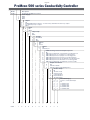
ProMinent ProMcon 500 series
Cooling Tower Treatment Package
ProMinent
®
Operation Manual
Model 520
Head Office: Unit 4, 4 Narabang Way
BELROSE NSW 2085
(PO Box 85, BELROSE WEST NSW 2085)
Ph: (02) 9450 0995 Fx: (02) 9450 0996
Email: sales@prominentfluid.com.au
ProMinent Fluid Controls Pty Ltd
QLD Office: 1048-1054 Beaudesert Road
COOPERS PLAINS QLD 4108
Ph: (07) 3246 5200 Fx: (07) 3246 5225
Email: pfcqld@prominentfluid.com.au
VIC Office: Unit 2, 88 Star Crescent
Hallam VIC 3803
Ph: (03) 8795 7430 Fx: (03) 8795 7431
Email: pfcvic@prominentfluid.com.au
Distributors Throughout Australia & New Zealand
WA: Ph: (08) 9458 9555 Fx: (08) 9350 6192
TAS: Ph: (03) 6244 7575 Fx: (03) 6244 7576
NT: Ph: (08) 8947 1008 Fx: (08) 8947 1009
SA: Ph: (08) 8275 8000 NEW ZEALAND: Ph: (64) 9571 3131 Fx: (64) 9571 2002 Email: [email protected]
Rev A:1st December 2004
Page 2
Index
Page
Cover .......................................................................................................................
1
Index ........................................................................................................................
2
Operation manual overview .....................................................................................
3
Operation manual overview continued ....................................................................
4
Operation manual overview continued ....................................................................
5
Operation manual overview continued & Specifications .........................................
6
SECTION 1 – Using The Keys, Display And Indicating Leds ..................................
7
SECTION 2 – Screen Menus And Setup Screens
2.1
Start-up Screens and Auto-Mode Displays .................................
2.2
Main Menu .................................................................................
2.3
Main Menu – Manual Operation ................................................
2.4
Main Menu – Change Setup - Basic ..........................................
2.5
Main Menu – Change Setup - Advanced ...................................
2.5.1 Advanced Menu – Change Setup - Biocide ...............................
2.5.2 Advanced Menu – Change Setup - Calibrate ............................
2.5.3 Advanced Menu – Passcode Protection ....................................
8
9
10
11
12
13
13
13
Terminal Connections ..............................................................................................
14
Identcode .................................................................................................................
15
Page 3
Operation Manual
ProMinent ProMcon 500 series
Cooling Tower Treatment Package
Model 520
The ProMinent ProMcon series 500 conductivity control package model 520 is a fully integrated
backboard mounted package with peristaltic pumps, or Concept Dosing pumps.
The package provides conductivity control via solenoid blow down and comes complete with:
• Probe
• Pumps
• Solenoid valve
• Conductivity controller
• Sample pipework
Optional accessories include the following:
Flow Switch, Sample Valve, Winter Cycle, 4-20 mA Monitoring and Alarm Relays.
The conductivity controller will control 2 biocide metering pumps each having 10 timer settings
per day with pre-bleed and bleed lockout available for each time.
The inhibitor pump can be controlled in different ways. It can be set to run all the time, to run
only when the tower is bleeding, controlled from a pulse water meter.
When set to run all the time, or when the tower is bleeding, there is a % on to off time that can
be set for varying the capacity of peristaltic fixed capacity pumps.
There are other features of your new conductivity controller that should be understood before
proceeding.
The LED alarms on the controller face can be deactivated if preferred. A flow input can be
activated if a sample flow switch is provided with the package or if an external no-flow contact is
available.
A slug dosing facility can be activated (with bleed lockout) to allow slug dosing of biocide(s) after
a tower clean.
Your own passcodes can be set for both the Advanced and Basic menus.
Options
Options available are ‘Summer Cycle’ or ‘Winter Cycle’ where different biocide dosing times with
or without prebleed and lockout can be set to start the tower bleed and dose chemicals during
the winter months when a tower may not be operating. This manual includes instructions for
winter cycle but it may not be included in your controller.
By adding another card, a 4-20 mA monitoring signal with alarm contacts is available for building
management.
Page 4
When your controller is set into operation, a scrolling menu keeps you informed.
For details see section 2.1
Section 1 describes the keys, display and the LEDs and should be read before proceeding.
Assuming your controller has not been set-up to your specific requirements go first to the
‘Advanced’ menu.
Main Menu
By holding the ‘enter’ key in for 2 seconds, you will enter 5 menus, Manual Operation, Bleed
Lockout, Season Mode, Change Set-up and Advanced.
Manual Operation
The Bleed, Inhibitor, Biocide ‘A’, Biocide ‘B’, and the tower recirculation pumps can all be
manually selected to run.
Bleed Lockout
A lockout time can be manually selected in hours and minutes and started.
Season Mode
Here either the ‘Summer’ or ‘Winter’ cycles can be selected, if this option is included.
Change Setup
Bleed
Here you can adjust your set-point in microsiemens per centimetre.
Inhibitor
If the inhibitor is set for water meter control you will be asked to set the number of pulses
received (1-100) for an inhibitor pump on-time of 1-100 seconds. If on % of bleed select the
percent of time you require the inhibitor pump to be on from 1 to 100%. If on continuous adjust
on-time from 1 to 100 seconds on in every 100 seconds.
Biocide
See menu screen details section 2.5.1
You are asked to select the timers required for Biocide A and Biocide B, Their on and off times
and the day or days of the week they are to operate.
Advanced See menu screen details section 2.1
Hold the enter key for 2 seconds
With the up down arrows select Advanced. See menu screen details section 2.5
You will be asked to enter a pass number. Your number is 500 (until you change your
passcode in the Advanced Menu)
Note: As standard a passcode of 500 is required to enter the Advanced
menu. If this passcode, and or the general menu passcode, is altered or
lost you will not be able to access the menus.
A break-in number is available from ProMinent, but you must provide the
serial number of the controller. To find the serial number, switch on the
instrument, watch the scrolling menu until <AUTO OPERATION> appears,
then press the HELP key.
Serial No
201
510
5101
will appear, 5101 is the Serial No
Page 5
Advanced has 9 sections (to be selected with the up/down arrows)
1.
2.
3.
4.
5.
6.
7.
8.
9.
10.
Inhibitor
Biocide
Flow Input
Fault LEDs
Slug Dosing
Bleed Lockout
Clock
Calibration Cell
Protect Season
Change Passcodes
When you arrive in the section required, press the enter key.
Inhibitor
% of Bleed
The Inhibitor pump can be set to any percentage from 1 to 100. If on 100% the
inhibitor will be dosed all the time the bleed solenoid is open. On 50% it will be dosed
for only half the time the bleed solenoid is open. This allows an adjustment of the
amount dosed with fixed capacity pumps like the ProFlex and DulcoFlex peristaltic.
Continuous
If continuous the inhibitor pump is powered up all the time. The dosing capacity is
adjusted with an on-off time adjustment from 1 to 100%.
Water Meter
When ‘Water Meter’ is selected, the controller receives a volt free pulse signal from
a water meter. A selection is made to accept a number of pulses, from 1 to 100, and
operate the inhibitor pump from 1 to 100 seconds.
Biocide
There are 10 on-off time settings for Biocide (A) and 10 on-off time settings for Biocide (B). If
Pre-bleed and or bleed lockout is selected in the Advanced menu, they still have to be activated
for each individual time setting in the ‘Change Setup’ menu. Pre-bleed is to 15% lower than setpoint, bleed lockout is up to 8 hours.
Flow Input
Enable ‘Flow Input or leave as off. When the optional Flow Switch is included with the package,
set the flow input to ON.
Fault LEDs
The fault LED can be made inactive for high or low conductivity, and for loss of sample flow.
Slug Dosing
This function can be used for manually slug dosing the tower perhaps after a tower clean.
Bleed Lockout
This lockout is to give the slug dosed biocide time to work before bleed can occur.
Page 6
Clock
Set the time and day. See menu screen details section 2.5
Calibrate Cell
Your new conductivity controller will be factory calibrated. You can however carry out your own
calibration with known solutions or after your manual check tower check. See menu screen
details section 2.5.2
Protect Season
This allows the ‘Winter’, ‘Summer’ cycles to be protected.
Change Pcodes
Here you can change the passcode for the Advanced menu, and enter a passcode for the
general menu.
-o0o-
Page 7
Section 1 - Using the keys, Display and Indicating LEDs
1.1
Keys
Menus
Down
Arrow
Up
Arrow
1.2
Move up or down to the
next menu item in this
Menu.
Numeric
and Time
Switching and
Enable/Disable
In Manual Operation Mode Increase or decrease the value of
the number (time) displayed on selects solenoid/Pump to switch
on/off without changing status of
the screen. A single arrow is
the other devices.
displayed when the limit is
Other Modes - Not applicable.
reached.
Enter
Key
Go to this menu item.
Accept the value (time) displayed
and go to the next screen.
Accept the state displayed
and go to the next screen.
ON/OFF
Key
Not applicable.
Accept the value (time) displayed
and go to the next screen.
Accept the state displayed
and go to the next screen.
ESC
Escape
key
Go to the previous level
menu.
Accept the value (time) displayed
and go to the next screen.
Accept the state displayed
and go to the next screen.
HELP
Help
Key
Display context-sensitive Help messages. Press ESC toreturn to the operational screen.
Display
The following Key characters are shown in the display to indicate the following:
Up-arrow only - at lower limit or bottom menu - Press up-arrow key to increase value or move up to previous menu
item.
Down-arrow only - at upper limit or bottom menu - Press down-arrow key to decrease value or move down to next
menu item.
Both arrows - Press up or down-arrow keys to increase/decrease value or move up/down to previous/next menu
item.
On/Off arrow - In manual mode, press ON/OFF key to switch solenoid pumps. Elswhere press ON/OFF key to
enable/disable feature.
Enter arrow - Press enter key to go to the displayed menu item or the accept teh displayed value/status and
advance to the next screen.
1.3
Indicating LEDs
Set-up Mode Indicator flashing red when in Set-up
Menu (with Auto-Mode)
indicator.
Auto Mode Indicator flashing green when
operating normally in Auto
Mode
- ProMinent Fluid Controls
Manual Mode indicator flashing red when operating
in Manual Mode
Fault indicator - flashing red
when conductivity out-of-limits
or no-flow alarm - refer to
display for details.
Page 8
Section 2 - Screen menus and set-up screens
2.1
Start-up screens and Auto-Mode Displays
START-UP
- ProMinent Fluid Controls
ProMcom 500
Version 2.02
<AUTO OPERATION>
Sat 15:45 hrs.
Conductivity:
1234 uS / cm
Bleed
Set Point:
OFF
1500 us
Hold ENTER Key down for 2 seconds to enter the
Set-up Menus - Sect 2.2
Current Conductivity reading - Displays
** OVERRANGE ** if above 5000 uS/cm.
Bleed Solenoid Status (ON/OFF)
Conductivity Bleed Setpoint.
Inhibitor
OFF
Duty: 100% Bleed
Inhibitor Pump Status (ON/OFF)
Inhibitor Mode - Tracking Bleed/Duty Cycle
Bio A
Bio B
Biocide Pumps Status (ON/OFF/Prebleed/Lockout)
* Displays only for the enabled Biocide Pumps.
OFF
OFF
*** WARNING ***
CONDUCTIVITY HIGH
*** WARNING ***
NO FLOW
Displays Alarm when conductivity goes below setpoint
by 20% or above setpoint by 20%
Displays only when Flow Monitoring is enabled and
flow ceases - Resets when flow resumes.
Page 9
2.2
Main Menu
To enter the Main Menu from the Auto-mode Revolving Displays:
Hold ENTER key down for 2 seconds.
2 secs
SELECT OPTION:
Manual Oprn
MANUAL OPERATION:
Bleed
Manual Oprn.
Bleed
OFF
Bleed Lockout
Inhib.
OFF
Season Mode
Bio A
OFF
Change Set-up
Bio B
OFF
Refer Sect 2.3
Manually Operate bleed Solenoid
and Inhibitor/Bio pumps:
• All relays are turned OFF on
entry.
• Auto Mode inhibited.
• Reset to Auto Mode after 15
minutes.
• Auto Mode resumes on Exit
Advanced
SET LOCK DURN:
06:55 min
SET SEASON MODE:
Winter Mode
Set the period of Bleed.
Select Summer or Winter Mode.
Summer Mode
Winter Mode
Down to next
menu item.
Up to previous
menu item.
Go to this menu
item.
Switch ON/OFF
where applicable.
ESC
HELP
Go to previous
menu.
Display Help
Screen.
CHANGE SETUP:
Bleed
Bleed
Inhibibitor
Refer Sect 2.4
Change:
• Bleed Setpoint.
• Inhibitor duty cycle.
• Biocide dosing times & days
set preebleed and or lockout.
Biocide
Advanced Setup
Inhibitor
Inhibitor
Biocide
Flow Alarm
Fault LEDs
Clock
Calibrate Cel
Change Pcodes
Refer Sect 2.5
Set:
• Inhibitor Mode - % of Bleed,
Continuous, Water Meter.
• Enable/Disable Bio-A and
Bio-B.
• Set pre-bleed and lockout
times.
• Enable/Disable Flow switch.
• Select alarm LEDs for Hi Cond,
Low Cond, No flow.
• Set current day and time.
• Calibrate the Conductivity Cell.
• Change Pcodes for menu entry
and Advanced
PASSCODE PROTECTION
Refer Sect 2.5.3
Page 10
2.3
Main Menu - Manual Operation
MANUAL OPERATION:
Bleed
OFF
MANUAL OPERATION:
Bleed
Bleed
OFF
Inhib.
OFF
Bio A
OFF
Bio B
OFF
W Circ
OFF
MANUAL OPERATION:
Inhibitor
OFF
MANUAL OPERATION:
Bio A
OFF
MANUAL OPERATION:
Bio B
OFF
Switch ON / OFF.
ESC
Revert to Main
Menu - Auto-Mode
MANUAL OPERATION:
W Circ
OFF
Notes:
• Bleed Solenoid, Inhibitor Pump
and Biocide Dosing Pumps are
switched OFF when Manual
Operation is selected.
• Manual Operation will revert to
Auto-Mode after 15 minutes.
• All relays are switched OFF on
exiting to Auto-Mode.
programmed settings will
resume after 1 minute or less.
• Bio-A and Bio-B screens will
only appear if these are
enabled,
(see Advanced Settings).
• Inhibitor, Biocide A, Biocide B
can be manually selected as
well as the main recirculation
pump.
Page 11
2.4
Main Menu - Change Set-up - Basic
Adjust Setpoint:
1234 uS/cm
CHANGE SETUP:
Bleed
Bleed
Set Conductivity Setpoint for
Bleed solenoid operation:
Range 100–5000 uSiemens/cm.
Inhibitor
Biocide A (Norm)
Inhibitor Mode:
% of Bleed 5 0%
Biocide B (Norm)
Inhibitor Duty
Continuous 0%
Water Meter
BIO-A OPTIONS:
Set Timers
Set Timers
Pre on/off
Set the % of time the inhibitor is
to be on for when the solenoid is
open adjustable 1-100%
• For continuous inhibitor dosing
there is a capacity time on
adjustment from 1 to 100
seconds on in every 100 secs.
• Set the number of pulses received from a water meter
– from 1 to 100 and select the
time pump is to be on for from
1-100 secs
Lock on/off
View Times
Reset All
BIO-B OPTIONS:
Set Timers
Set Timers
Pre on/off
Lock on/off
View Times
Select Timer: A
0123456789
Reset All
Set Bio-x T n ON
at: 10:15
•
•
•
Note: Timer menus for
Bio-A and Bio-B only
displayed if the Bio is
enabled - Refer
Advanced Setup Biocide.
x = Biocide A
n = Rimer 0........9
Go from one
Timer to next
Set day ON (^) or
OFF (_)
Set Bio-x T n OFF
at: 10:15
BioxTn SMTWTFS
_^_ _^_ _
NOTES:
For each Biocide Timer as required – Bio x Timer n:
• ENTER to accept setting
• 24 hour clock
00:00 to 23:59 hrs
• Maximum timer duration 08:00
hours.
• ESC to return to Menu
Select Days of Week that Timer is
to operate:
•
and
arrows to move
cursor to day.
•
key to toggle selected day
ON or OFF.
• bar _ indicates day OFF.
• caret ^ indicates day ON.
• ESC to return to Menu
Page 12
2.4
Main Menu - Change Set-up - Advanced
PASSWORD PROTECTED Refer Sect. 2.5.3
ADVANCED SETUP:
Inhibitor
Inhibitor Mode:
% of Bleed
Inhibitor
% of Bleed
Biocide
Continuous
Flow Input
Water Meter
Set the Inhibitor to be
• On all the time.
• On for a % of the Bleed time.
• Continuous from a Water
Meter.
• Inhibitor, Biocide A, Biocide B
can be manually selected as
well as the main recirculation
pump.
Fault LEDs
Slug Dosing
Select Biocide:
Bio-A
•
Bleed Lockout
Bio-A
Clock
Bio-B
•
•
Calibrate Cell
Protect Seas
Change Pcodes
•
Flow Input:
Enable
OFF
•
Enable/disable Biocide A and
B dosing.
Set each timer pre-bleed and
Lockout periods.
REFER Sect. 2.5.1 pump.
ON/OFF Key
to enable/
disable Flow Alarm indication.
Press ENTER Key to accept
setting.
Show Alarm LED for
Hi Cond
OFF
Go from one
Timer to next
Hi Cond
OFF
Hi Cond
OFF
No Flow
OFF
Slug Dose Option:
Enable
OFF
Go from one day
to next
Set Highlighted day
as Current Day
Bleed Lockout Option:
Enable
ON
Set Clock Time:
14:50 hrs.
•
•
24hr clock – 00:00 to
23:59 hrs
ENTER Key to accept.
Set Current Day:
SMTWTFS
Place Cell in
Std. Solution
Press Enter Key
When Ready
Move Between Entry
and Advanced
Change Menu Entry
Pcode:
0
•
&
arrows
to select day
ENTER Key
to accept.
Calibrate Conductivity Cell against
Standard Solution.
• REFER Sect. 2.5.2
Season Mode:
Protect
OFF
Change Pcode
Number
•
Change Advanced
Pcode:
500
Page 13
2.5.1
Advanced Menu - Change Setup - Biocide
Select Biocide:
Bio-A
Bio-A
Select Output:
Bio-x
ON
Set whether Bio-A and Bio-B
dosing is enabled or disabled.
Pre Duration:
Bio-x 00:00
Set whether Bio-A and Bio-B
dosing is enabled or disabled.
Lock Duration:
Bio-x 00:00
If Bio-A and or B is enabled,
select Lockout duration.
• Range 00:00 to 08:00 hrs.
Bio-B
2.5.2
Advanced Menu - Change Setup - Calibrate
Place Cell in
Std. Solution
Press Enter Key
When Ready
2.5.2
Press & arrows until
conductivity reading equals
conductivity of standard
solution.
• Press ENTER Key to save
the Cell Constant.
• Cell Constant range 0.01
to 5.00.
Lock Duration:
Bio-x 00:00
Advanced Menu - Passcode Protection
SELECT OPTION:
Advanced
Lock Duration:
Bio-x 00:00
INCORRECT
CORRECT
ADVANCED SETUP:
Inhibitor
Inhibitor
Biocide
Flow Alarm
Fault LEDs
Clock
Calibrate Cell
Change Pcodes
Passcode Error
!!!!!!!
INCORRECT PASSCODE:
after 3 tries
Returns to main Menu
CORRECT PASSCODE:
Enables the Advanced
Menu
Page 14
DC 520 CTP CONTROLLER
PROBE
CELL
SHLD
TC +
TC -
FLOW
SWITCH
WATER
METER
FLO
XT1
GND
MTR
XT2
V+
RL - A
N
RL - B
RL - C
N
RL - D
EARTH
RL - E
N
RL - F
EARTH
A
POWER
240V AC
N
E
Page 15
ProMcon 500 series Conductivity Controller
Model
C 520 -
Description
Conductivity 0-5000 microsiemens
1
2
X
Power Supply:
240 V
110 V
Other
0
1
2
X
Output:
Nil
Buliding Management System ... 6 status relays and 4-20 mA current loop output
As 1 but relays only no output
Other
0
X
Input:
Nil
Other
0
X
Temp Comp:
Nil
Other
0
2
3
Sockets:
Hard Wired
Two
Three
0
1
Sensor:
Nil
Sensor
0
1
Option:
Nil
Winter Cycle
0
B
C
D
E
F
G
H
HDPE Mounting Board with Sample Pipework:
Nil
500 x 325 c/w Pipework, solenoid valve & conductivity cell
500 x 400 as per B, for 1 x pump with 1 x dosing point
500 x 400 as per B for 2 x pumps with 2 x dosing points
500 x 400 as per B for 3 x ProFlex with 3 x dosing points
600 x 500 as per B for 3 x Concept/Beta with 3 x dosing points
600 x 500 as per B for 3 x Dulcoflex with 3 x dosing points
500 x 325 c/w Pipework, & conductivity cell with hosetails
0
1
2
Sample Flow Switch:
Nil
With Flow Switch
With Flow Switch & Regulating Valve
0
4
5
7
8
9
C520
-
1
0
0
0
0
1
0
D
0
4
Inhibitor Pump:
Nil
1.0 l/h Concept
2.0 l/h Concept
2.4 l/h Dulcoflex
0.8 l/h Dulcoflex
1.6 l/h Dulcoflex
X
0
4
5
7
8
9
X
0
4
5
7
8
9
2
4
Biocide Pump(s):
Select 1 or 2 Biocide Pumps
Ni
1.0 l/h Concept
2.0 l/h Concept
2.4 l/h Dulcoflex
0.8 l/h Dulcoflex
1.6 l/h Dulcoflex