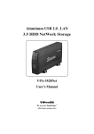
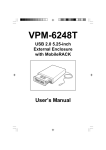
1
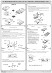
For Removable Docking Modules with 3.5"/2.5" HDD
or Optional for zip /SuperDisk LS-120/MO/TR-4 Tape
or ATA Flash Memory Reader
TM
TM
Model VP-10LS
Model VP-10LSF
Model VP-10K
Model VP-10KF
Model VP-10KP
Model VP-10KPF
Model VP-15
Installation Manual
We are your DataBridge
TM
http://www.vipower.com
Table of Contents
1-1 Introduction .......................................................................... 1
Features .......................................................................... 2
Unpacking Your Mobile Rack .......................................... 2
IDE Basics ...................................................................... 2
2-1 Hardware Installation ........................................................... 3
Mobile Rack Components ............................................... 3
Installing Mobile Rack Docking Case .............................. 4
Mounting a Drive in the Drive Case ................................ 4
3-1 Using the Mobile Rack ......................................................... 8
Non Hot-Swapping Models ............................................. 8
Hot-Swapping Models ..................................................... 9
PROPRIETARY NOTICE
ViPowER Inc. makes no warranty of any kind with regard to this material,
including, but not limited to, the implied warranties of merchantability
and fitness for a particular purpose. ViPowER Inc. shall not be liable for
errors contained herein or for incidental or consequential damages in
connection with the furnishing, performance, or use of this material.
This document contains proprietary information which is protected by
copyright. All rights are reserved. No part of this document may be
photocopied, reproduced, or translated to another language without the
written consent of ViPowER Inc. The information contained in this
document is subject to change without notice.
IBM is a registered trademark and PC, AT are trademarks of International Business Machines Corporation.
Windows and Windows NT are registered trademarks of Microsoft Corporation.
All other trademarks belong to their respective owners.
Patent: USA: 5694290
Taiwan: 126661 & 129379
Germany Nr. 297 15 551.2 & Nr. 297 22 974.5
Japan: 3047936 & 3050489
China: ZL 97 2 03156.1
Patent Pending: U.K, France, Korea
© Copyright 1998 by ViPowER, Inc.
9/98A
This manual will guide you through the installation of the VP-10LS and
VP-10K Series Mobile Rack Removable Docking Modules.
Mobile Rack Models:
VP-10LS
VP-10LSF
VP-10K
VP-10KF
VP-10KP
VP-10KPF
VP-15
IDE interface, Latch-lock/Slide Switch
IDE interface, Latch-lock/Slide Switch with Cooling Fan
IDE interface, Key-lock
IDE interface, Key-lock with Cooling Fan
IDE interface, Key-lock Power Switch
IDE interface, Key-lock Power Switch with Cooling Fan
IDE interface, Drive Case
Model Number Code Descriptions for Ordering Information:
V P - 1 0 L S (F)
1
1
2
3
4
5
6
2 3 4 5
6
ViPowER
Interface Type ..........
Body ........................
Lock Type ................
Power Switch ...........
Cooling Fan .............
1 = IDE, 2 = SCSI, 3 = Wide SCSI
2 = Out-Frame, 5 = In-Tray Box, 0 = Frame + Tray
L = Latch-lock, K = Key-lock
S = Latch Switch, P = Power IC Switch
F = Fan
NOTE
Although there are certain feature differences between the Mobile
Rack models, the installation for all models is the same. For
instructions on how to use your Mobile Rack, please refer to the
section that applies to your Mobile Rack model.
1-1 Introduction
Congratulations on your purchase of a Mobile Rack Removable Docking Module.
The Mobile Rack is the perfect solution for data backup and transporting data
between computers. It enables portability of 3.5-inch/2.5-inch IDE and ATAPI
devices such as hard disk, SuperDisk LS-120, MO, TR-4 tape, zip drives and ATA
flash memory readers.
TM
TM
The Mobile Rack is form-fitted for a standard PC/AT 5.25" half-height bay. Its drive
case can accept most half-height 3.5" and 2.5" drives (with separately purchased
adapter cables). Not being limited by memory size, you can install any capacity drive.
Mobile Rack Installation Manual
1
Features
• Compatible with tower or desktop PC, external subsystem & RAID system
cases
• Enables portable use of hard disk, LS-120, MO, TR-4 tape, zip and other IDE
and ATAPI devices
• Drive bay module for mounting a 1.0-inch height, 3.5-inch or 2.5-inch IDE
or ATAPI device in a 5.25-inch drive bay
• Supports fixed 3.5-inch hard disk drives and 2.5-inch hard disk drives
(requires 2.5-inch drive adapter cable)
•
•
•
•
•
•
•
•
Convenient pull-out handle
Safety lock feature
Power on/off feature (Models VP-10KP, VP-10KPF and VP10LS, VP-10LSF)
LED indicators for power and drive activity
Built-in cooling fan (Models VP-10LSF, VP-10KF and VP-10KPF only)
Drive case is interchangeable between all models
Fully compatible with MS-DOS, Windows® 3.11/95/98/NT, OS/2 Warp
Dimensions: 8.4" (D) x 5.8" (W) x 1.6" (H)
Unpacking Your Mobile Rack
Before installing the Mobile Rack, verify that the following items are included in the
carton. If any parts are damaged or missing, please contact your local dealer or sales
representative immediately.
1. One Mobile Rack Removable Docking Module
2. Eight mounting screws
3. One user’s guide
IDE Basics
IDE is an acronym for Integrated Device (Drive) Electronics and is sometimes referred
to as an ATA (AT Attachment) interface. It is the most commonly used interface for
hard disk drives installed on personal computers. Other devices like CD-ROM, tape,
optical drives, and so on have adapted a variation called ATAPI (ATA Packet Interface) and can be intermixed with standard IDE drives because they use the same
cabling and electrical interface.
Most systems today have two IDE channel connectors that are typically referred to as
primary and secondary ports. Each IDE port can have a maximum of two devices that
must be uniquely identified, typically by the setting of a jumper as a ‘master’ or ‘slave’
device.
2
Mobile Rack Installation Manual
2-1 Hardware Installation
The Mobile Rack Docking Module is designed to install in any PC/AT or Pentiumclass computer that has an available 5.25-inch half-height drive bay. General instructions
for installing the Mobile Rack are given since the design of computer
cases varies. Refer to your computer’s manual whenever in doubt.
Mobile Rack Components
The Mobile Rack is comprised of two components:
Docking Case [VP-12 (L)(S)(F)(K)(P)]
Drive Case (VP-15)
Mounting
Holes
Power ON/OFF
LED Indicator
Slide Lock/Power Switch
Drive Activity
LED Indicator
Latch Lock Model Mobile Rack Docking Case
Mounting
Holes
Power ON/OFF
LED Indicator
Slide Lock/Power Switch
Drive Activity
LED Indicator
Key Lock Model Mobile Rack Docking Case
Mobile Rack Installation Manual
3
Power
Connector
Data Interface
Cable
Bottom
Mounting Holes
Side
Mounting Holes
Handle
Removable Front Panel
for Removable Media Drives
Mobile Rack Drive Case VP-15 (with cover removed)
Installing the Mobile Rack Docking Case
1. Turn OFF the power to your computer and any other connected peripheral
devices. Follow the precautions for static electricity discharge:
• Discharge any static electricity build up in your body by touching a grounded
metal surface such as the computer case, if plugged in.
• During installation procedures, avoid any contact with internal parts.
2. Unplug the power cord from the back of the computer.
3. Remove your computer’s cover.
4. Remove the computer’s front cover plate from the 5.25-inch drive bay you plan
to install your Mobile Rack into.
5. Remove (separate) the Mobile Rack drive case from the docking case by lifting
the handle and pulling it out.
6. Slide the docking case into the 5.25-inch drive bay.
Mounting
Mounting
Screws
Screws
Docking Case
(All Models)
Mounting
Screws
Install the Mobile Rack Docking Case into the Drive Bay
4
Mobile Rack Installation Manual
7. Attach an existing IDE 40-pin data cable from the system motherboard to the
40-pin connector on the back of the docking case. Most connectors are keyed
for proper insertion. If there is no key, orient the cable so the pin-1 colored
stripe edge is closest to the power connector.
8. Attach an available 4-pin power cable from the system’s power supply to the 4-pin
connector on the back of the docking case. The power connector is ‘D’ shaped to
ensure proper orientation when making the connection.
Pin 1
40-pin IDE Connector
Power Connector
Docking Module IDE and Power Connectors
9. Replace the computer’s cover and reconnect the power and other external
cabling.
Mounting a Drive in the Drive Case (VP-15)
Proceed with the following steps to install a 3.5-inch drive device in the Mobile Rack
drive case. (Note: a special adapter kit is required in order to install a 2.5-inch drive.)
1. Remove the Mobile Rack drive case cover by sliding it towards the back of
the unit.
Slide Cover Off
Remove the Drive Case Cover
Mobile Rack Installation Manual
5
2. If you plan to install a drive that features removable media such as a zip, TR-4 tape,
MO, LS-120 drive, or ATA Flash memory reader, carefully punch out the center
part of the front panel.
Center Part
of Front Panel
Removed
Remove Front Panel for Removable Media Drives
IMPORTANT
3. If you are installing a new hard drive into the Mobile Rack, you may need to
configure the drive before you install it. Refer to the drive manufacturer’s documentation and configure the drive as ‘Master’, ‘Cable Select’, or ‘Slave’ depending
on the configuration of your computer. After you complete this installation, you
may also need to re-configure the computer’s BIOS Setup to make the drive
functional in the system.
4. The drive case’s 40-pin IDE cable supports 3.5-inch drives. Attach the power
and IDE cables from the Mobile Rack drive case to the drive.
The power connector is ‘D’ shaped to correctly orient the connector. The
colored stripe on the IDE cable should be closest to the power connector.
To install a 2.5-inch drive, you must purchase a ‘44-pin to 40-pin’ connector
adapter from your local computer dealer.
5. Carefully position the drive inside the drive case.
6
Mobile Rack Installation Manual
Power Cable
Colored Stripe
Mounting
Screws
IDE Data Cable
Mounting
Screws
Install the Drive in Drive Case
6. Secure the drive in place using the supplied mounting screws. Use the mounting
holes on the sides or bottom, depending on the design of the drive.
7. Slide the drive case cover back on. The hardware installation is complete. Your
Mobile Rack drive case is ready to use.
Mobile Rack Drive Case Ready for Use
Mobile Rack Installation Manual
7
3-1 Using the Mobile Rack
Non Hot-Swapping Models
(Models VP-10K, VP-10KF)
Key-lock models VP-10K and VP-10KF do not support hot-swapping. Your
computer must be POWERED OFF when the drive is inserted or removed. Once
installed, the removable drive can be used like any other drive.
To insert the Mobile Rack drive case:
1. Make sure the computer is OFF.
2. Insert the Mobile Rack drive case (with drive installed) into the installed Mobile
Rack docking case and push firmly until the drive is seated.
3. Insert the key and turn key to the right to lock.
4. Turn your computer ON. The LED on the Mobile Rack should light after a slight
delay. The installed Mobile Rack device is ready to use.
Lock Position
To remove the Mobile Rack drive case:
1. Turn your computer OFF.
2. Insert the key and turn key to the left to unlock.
3. Gently pull on the Mobile Rack handle to slide the drive case out.
Unlock Position
WARNING
• DO NOT remove the drive case while the drive is working.
Damage to data may result.
• The Key-Lock keyswitch must be in the Lock position when in use.
This prevents removal while working.
• Always turn the system power OFF before removing or inserting
the drive case.
8
Mobile Rack Installation Manual
Hot-Swapping Models
(Models VP-10LS, VP-10LSF, VP-10KP, VP-10KPF)
Latch-Lock models VP-10LS and VP-10LSF, and Key/Power Lock models
VP-10KP and VP-10KPF support hot-swapping. The power to your computer can
be ON when the drive is inserted or removed. Use the Latch-Lock switch or
Key/Power Lock keyswitch to turn power to the drive ON after inserting
it, and OFF before removing it.
To insert the Mobile Rack drive case:
1. Insert the Mobile Rack drive case (with drive installed) into the installed Mobile
Rack docking case and push firmly until the drive is seated.
2. For models VP-10LS/VP-10LSF, slide the latch-lock left, to the lock position. For
models VP-10KP/VP-10KPF, insert the key and turn key to the right to lock. The
LED on the Mobile Rack should light after a slight delay. The installed Mobile
Rack device is ready to use.
Lock Position
Lock Position
To remove the Mobile Rack drive case:
1. For models VP-10LS/VP-10LSF, slide the latch-lock right, to the unlock position.
For models VP-10KP/VP-10KPF, insert the key and turn key to the left to unlock.
Note that the power LED on the Mobile Rack should now be OFF.
2. Gently pull on the Mobile Rack handle to slide the drive case out.
Unlock Position
Mobile Rack Installation Manual
Unlock Position
9
Printed on recycled paper.