Transcript
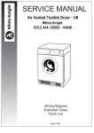
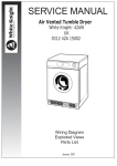
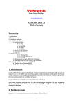
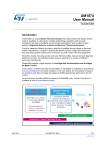
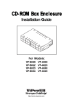
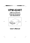
VP-1028 USB 2.0 out Frame to IDE Inner Tray with Backup Module Installation Guide
Exploded View
Step 2-2.
3. Perform the following steps to enable the USB function of the VP-1028 USB 2.0 out Frame to
IDE Inner Tray with Backup Module.
a). With the computer cover removed, ensure the power is OFF, and all power cords and cables
from the back of the computer are unplugged.
b). Select an unused I/O expansion slot at the back of your computer and remove its slot cover.
Save its screw for securing the USB slot bracket.
c). Install the USB slot bracket and secure with the previously removed screw.
d). Connect the small 5-pin connector on the bracket to the USB connector on the back of the
VP-1028 out Frame.
(Remove the
IDE Inner Tray)
Mounting
Screw
Backup
Module
USB connector to
Computer's USB Port
USB Bracket
Installed in
Expansion
Slot
(Expolded View)
VP-1028
USB 2.0 out Frame
Connection to
VP-1028
out Frame
(installed in
Computer)
VP-15
IDE Inner Tray
Mounting
Holes
LED Indicators
VP-1028
out Frame
Backup Module
e). Replace the computer’s cover and reconnect the power and other cable connections.
And plug the bracket mounted USB connector into any available USB port on the computer.
Latch-Lock/Power Switch
Hardware Installation
Step 1.
Step 3.
1. Turn OFF the power to your computer and any other connected peripheral devices. Follow the
precautions for static electricity discharge:
(a). Discharge any static electricity build up in your body by touching a grounded metal surface such as
the computer case, if plugged in.
(b). During installation procedures, avoid any contact with internal parts.
Before insert the VP-15 IDE Inner Tray into the
VP-1028 out Frame installed in the computer,
perform the following steps to mounting a Drive
in the VP-15 IDE Inner Tray.
2. Unplug the power cord from the back of the computer. And remove your computer’s cover,
and the computer’s front cover plate from the 5.25-inch drive bay you plan to install the VP-1028 into.
3. Slide the latch-lock switch on the front panel of the VP-1028 USB 2.0 out Frame RIGHT,
to UNLOCK. Remove (separate) the VP-15 IDE Inner Tray from the VP-1028B USB 2.0 out Frame by
lifting the handle and pulling it out.
4. Slide the VP-1028 USB 2.0 out Frame into the 5.25-inch drive bay.
5. Position the VP-1028 USB 2.0 out Frame so its mounting holes align with the 5.25-inch drive bay’s
mounting holes. Secure with the supplied mounting screws (two on each side).
Mounting
Screws
Slide Cover Off
1. Remove the VP-15 IDE inner tray cover by
sliding it towards the back of the unit.
2. If you plan to install a drive that features removable
media such as a zip, TR-4 tape MO, LS-120 drive,
or ATA Flash memory reader, remove the center part
of the front panel.
3. Connect the cables from the VP-15 IDE inner tray
to the appropriate pin connecotrs of the 3.5" HDD.
Attach the power and IDE cables from the VP-15
IDE inner tray to the 3.5" HDD. The colored stripe
on the IDE cable should be closest to the power
connector. Carefully position the 3.5" HDD inside
the VP-15 IDE inner tray. Secure the HDD in place
using the supplied mounting screws.
Use the mounting holes on the sides.
Center Part of
Front Panel
Removed
Mounting
Screws
Power
Connector
Colored Stripe
Mounting
Screws
4. Replace the VP-15 IDE inner tray cover by
sliding it back on.
VP-1028
out Frame
IDE Data
Cable
Mounting
Screws
(Slide into)
5.25-inch Drive Bay
Step 2-1.
Step 4.
1. Connect an available 4-pin power cable from the system’s power supply to the 4-pin connector on
the back panel of the VP-1028 USB 2.0 out Frame.
Insert the VP-15 IDE Inner Tray into the VP-1028 USB 2.0 out Frame installed in the computer.
And slide the latch-lock switch on the VP-1028 USB 2.0 out Frame LEFT, to LOCK.
USB Connector
Power
Connector
Computer
VP-1028 out Frame USB and Power Connectors
2. Installation for USB Interface:
The computer must be USB-ready in order to implement the USB feature of the VP-1028 USB 2.0
out Frame to IDE Inner Tray with Backup Module. An I/O expansion slot bracket with a USB interface
cable is supplied for connecting the VP-1028 out Frame to an available USB port on the computer.
Connect to
USB Port on
Computer
Connect to USB connector
on VP-1028 out Frame
LEFT
Lock/ON
Position
RIGHT
Unlock/OFF
Position
VP-1028
USB 2.0 out Frame
to IDE Inner Tray with
Backup Module
Slide the Latch-switch LEFT to LOCK
The hardware installation is complete.The VP-1028 USB 2.0 out Frame to
IDE Inner Tray with Backup Module is ready to use.
USB I/O Expansion Solt Bracket
ViPowER
www.vipower.com
VP-1028 Rev.1.0 / 04.14.2005