1
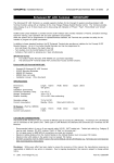
CONCEPT IQ. Combined Installation Manual
Rev 1.0 05/03
p1
Installation Manual
Contents
Section One: Concept IQ Hardware Overview
1.1 Typical Installation
1.2 Concept IQ Lockable Cabinet
1.3 Connecting Zone Inputs
1.4 Input & Output Connections
1.5 IQ Expansion Module
Section Two: Installation Manuals
1.
Control Module, 995501/ 995502
2.
Standard LED Terminal, 995500
3.
Enhanced LED Terminal, 995500EN
4.
Enhanced RF LED Terminal, 995500V2RF
5.
RF Module, 995507V2
6.
Expansion Card, 995503 /995504
7.
Programming Key, 995510
8.
Programming Key and Flash Interface, 995511 / 995515 / 995516
9.
DTMF Card, 995505
NOTE:
©
Factory Default PIN Codes:
User 1. Installer:
2345
User 2. Master User:
0123
2003. Inner Range Pty. Ltd.
Part No: 635501INST
p2
CONCEPT IQ. Combined Installation Manual.
Rev 1.0 05/03
1.1 Typical Installation
Up to 4 LED
Terminals
To PC for
Upload/Download
Siren /
Strobe
To Central Station
DTMF module
Connector
Up to 16
Zone Inputs
Control of up to 10 Auxiliary Devices
(lights, sprinklers, pumps)
CONCEPT IQ. Combined Installation Manual
Rev 1.0 05/03
1.2 Concept IQ Lockable Cabinet
•
IQ lockable cabinet with room for back up battery.
•
Cut outs in sides and rear of cabinet allow for cable entry.
•
Tamper switch fitted to right hand side center will alarm if cabinet door is
opened or cabinet is removed from wall
p3
p4
CONCEPT IQ. Combined Installation Manual.
Rev 1.0 05/03
1.3 Connecting Zone Inputs
Connections for inputs 1 – 4
showing 0V as common.
Zone Doubling (3K3, 1K and 6K8) with Tamper recognition
For Zone Doubling WITH tamper recognition the 1K EOL MUST be at the 2nd PIR
Cabling MUST be run from the 1st PIR NOT from the panel
For Zone Doubling Without tamper recognition the 1K EOL can be anywhere in the line
1K – Seal on PIR 1 & 2
4K3 – Alarm PIR1
7K8 – Alarm PIR 2
11K1 – Alarm PIR 1 & 2
S/C or O/C - Tamper
Panel
Connections
st
1 . PIR
N/C Alarm
Contact
N/C PIR
Tamper
3K
nd
2 . PIR
1K
N/C PIR
Tamp
6K
N/C Alarm
Contact
CONCEPT IQ. Combined Installation Manual
Rev 1.0 05/03
p5
1.4 Input & Output Connections
Connections for:
•
Siren (8 ohm) SPK to DET+
•
Only ONE Standard 8 ohm speaker or 2 x 4 ohm in SERIES (max SPK load is 8
ohms)
•
Auxes: SPK or Aux 0 (selectable as siren or Aux at Loc 872 Option 7) 1 & 2 :
OUT 1 & OUT 2 to DET + (max 200mA each)
•
Max current available – 600mA
Connection for N/O Tamper switch,
No EOL resistor required.
Port 0 Connector for Upload/
Download or Program Key.
p6
Rev 1.0 05/03
CONCEPT IQ. Combined Installation Manual.
1.4 Input & Output Connections
(cont)
Connector for Firmware upgrading and factory default
DTMF Port for domestic
dialling or remote
telephone access
Zone Expander Port for
additional 8 zone inputs
and/or 8 auxiliary outputs
1.5 IQ Expander Module
8 Auxiliaries (AX3 - AX10)
maximum 200mA each
8 zone Inputs (ZN9 ZN16)
CONCEPT IQ. Combined Installation Manual
Rev 1.0 05/03
p7
Control Module 995501 / 995502
Contents
Control Module Parts List .............................................................................................................1
Specifications ................................................................................................................................1
Installation Procedure ...................................................................................................................2
Connection Details. Zone Inputs (Detectors), Tamper switch and Fuses .............................. 3
Mode 3 Telephone line connection ..............................................................................................3
Connection Details. Power, Warning devices & LAN ................................................................ 4
Control Module Parts List
-
Control Module PCB mounted in metal enclosure.
User Manual.
Installation Manual. (This document)
Installation Kit containing: (Contents may vary outside Australia)
- 4 x Pan Head Self-tapping screws 4x6mm. Used to secure the enclosure cover.
- 5 x plastic “D” bungs. Must be fitted to all unused cable entry cutouts in the cover.
- Telecom Line cord. (Note: Non-standard configuration. Only suitable for use with this product)
- 10 x 3k3 End-of-line resistors. (orange-orange-black-brown-brown) Used for Single EOL / Dual EOL / Zone Doubling.
- 10 x 6k8 End-of-line resistors. (blue-grey-black-brown-brown) Used for Dual EOL or Zone Doubling.
- 10 x 1k End-of-line resistors. (brown-black-black-brown-brown) Used for Zone Doubling.
- Tamper switch.
- Tamper switch bracket.
- 2 x 6 Way plug-on screw terminals. (Only for PCBs that do not have fixed terminal blocks fitted)
- 1 x 3 Way plug-on screw terminals. (Only for PCBs that do not have fixed terminal blocks fitted)
- 5 x 2 Way plug-on screw terminals. (Only for PCBs that do not have fixed terminal blocks fitted)
- 2 x 6.3mm Tamper switch connectors.
- Battery connection lead, 220mm, pre-assembled.
- 1 x 2 Amp M205 (20mm) Fuse. (Spare)
Electrical Specifications
Power Supply I/P:
Plug pack Mains Supply:
Plug pack Output:
PCB AC Input Voltage:
Battery Capacity:
DC Operating Voltage (Batt I/P)
Battery Input Fuse (F1):
Power Supply O/P: Current:
Fuse Protection (F2):
Auxiliary Outputs:
OUT1 (Strobe) / OUT2
Siren Output (SPK): Maximum Load:
NOTES:
240V AC -10% / +10%. 50 Hertz.
16V AC. 1.0 Amperes.
16V AC.
12V. 7AH. Sealed Lead Acid Battery.
9.5 to 14 V DC. (Low Battery alarm activated at 11.2V +/- 0.3V)
5 Ampere.
Total combined current required by devices connected to
“DET+” and “LAN+” must not exceed 600 milliAmps.
2 Ampere. (DET+ and LAN+)
Max. switched current = 200mA per Auxiliary. (Open Collector)
8 Ohms. (i.e. 1 x 8 Ohm Speaker only. Additional speakers must
not be connected in parallel)
1) ALWAYS REPLACE FUSES WITH THE SAME FUSE TYPE AND VALUE!
2) See data supplied with detectors and output devices for current consumption.
Mechanical Specifications
Dimensions:
Weight:
Height: 260 mm.
Width: 265 mm.
4.2 kg. (Cabinet & cover, PCB and 7AH battery)
Depth: 80 mm.
Plug pack = 0.6kg
Environmental Specifications
Continuous Operating Temperature
Storage Temperature
Relative Humidity (Non condensing)
©
2003. Inner Range Pty. Ltd.
0 to +50 °C
-20 to +70 °C
15 to 85 %
Part No: 635501V2
p8
CONCEPT IQ. Combined Installation Manual.
Rev 1.0 05/03
Installation Procedure
1. Installer. The system must be installed and maintained by a competent, qualified installer who holds appropriate
licences for Telecommunications and Security System cabling in accordance with local Regulations.
2. Location. The Control Module must be installed in a secure location near an AC Power outlet and Telephone line
connection. Install the unit where it will not be subject to temperature or humidity outside the specified range, and will
not come into contact with water, other liquids, high dust levels or chemical atmospheres.
Adequate ventilation must be provided around the cabinet (50mm min.) to ensure that heat from any other source
does not cause the Control Module to operate at an unsafe temperature.
3. Positioning. Orientation of the cabinet MUST be as per the illustration below with the battery at the bottom.
Fit the Tamper switch into the hole provided in the Tamper switch bracket. The Tamper switch bracket must be
positioned in the slot provided and under the base of the cabinet, before the cabinet is secured to the wall.
When wired to the “TAMP” input, Tamper switch alarms if the cabinet is removed from the wall or the cover is opened.
4. Mounting. The cabinet must be secured to a flat, solid, vertical surface using appropriate fasteners through the 4
holes provided in the base, and must be positioned to provide unhindered access for installation and maintenance.
The two mounting holes in the top of the cabinet are keyhole slots to assist with positioning.
When mounting onto flammable surfaces, a fire protection backplate MUST BE INSTALLED.
5. Power. (Plug Pack and cable color may vary outside Australia) Strip 5mm of insulation from the ends of the 3 Plug
pack cable conductors. Terminate the 16VAC conductors into the “AC” Input connections, and the Earth wire (Green/
Yellow) into “BATT -” on the PCB.
CAUTION: Do not connect the Plug pack to an AC outlet until all wiring is complete and checked.
6. Battery. Connect the pre-assembled battery cable into the “BATT +” and “BATT -” connections on the PCB.
CAUTION: Do not connect the Terminals to the Battery until all wiring is complete and checked.
7. Cabling. All cabling must enter the cabinet via the existing cutouts provided in the rear and sides. Additional holes
must not be cut in the cabinet. Installation of Cables both inside the cabinet, and external to the cabinet, must
conform to the appropriate Standards for Security and Telecommunications systems.
Cables must be protected at the entry points by grommets or by allowing the conduit to protrude into the cabinet.
The “D” Bungs provided must be fitted to all unused cable entry cutouts.
DO NOT connect the LAN “CLK” & “DATA” wires to the Control Module until all LAN Modules (e.g. LED Terminals) are
Commissioned.
8. Diagnostics. The “STATUS” Lamp on the Control Module can be used to assist with troubleshooting and testing.
SLOW FLASHING:
MicroProcessor OK (Running)
FAST FLASHING:
Controller is Dialing.
MicroProcessor Not running, OR Programming Key Upload or Download in progress.
NOT FLASHING:
9. Cover. In order to comply with regulations the cover must always be correctly re-fitted following any installation or
maintenance work. Engage the hinges on the Left-hand side and fasten the cover tightly to the cabinet using all four
(4) of the screws provided. Screw holes are located on both edges of the two Right-hand side corners.
^
Top mounting holes (x2).
Step 4.
^
STATUS Lamp.
Step 8.
JP9. Mode 3 Line Socket
for connection to Telecom
Line. (Special cable
supplied must be used)
Port 1. Serial Comms Port.
(995502, IQ Plus only)
(Prog. Key or PC or Printer)
Port 0. Serial Comms Port.
(Prog. Key or PC)
Tamper switch bracket.
(and Battery retainer)
Step 3.
<
T1. 16V AC Power
connections. Step 5.
>
Latch for optional lock.
T3. Battery connections.
Step 6.
12V, 7AH Battery position.
Step 6.
Rear cable entry cutout.
Step 7.
Bottom Mounting Holes (x 2).
Step 4.
V
< Location of Side Cable
entries. Step 7.
CONCEPT IQ. Combined Installation Manual
Rev 1.0 05/03
p9
Connection Details. Detectors, Tamper switch and Fuses
F1. Battery Input Fuse. 1A. M205.
F2. PWR Fuse. 1A. M205.
T2. “TAMP”. Dedicated Cabinet Tamper
input. Tamper switch supplied.
No End-of-line resistors necessary.
Detector
T6 and T7. Zone Input connections.
C
EOL
Res.
3k3 Typ.
Tamp.
NC
C
Alarm
NC
Detector
C
EOL
Res.
3k3 Typ.
6k8 Typ.
1st Detector
C
Alarm
NC
C
Tamp.
EOL
1k
NC
EOL
3k3
NC
2nd Detector
C
NOTE:
The 1k EOL
Resistor must
be fitted at the
2nd Detector.
Tamp.
C
Alarm
6k8
NC
Tamp.
NC
C
Alarm
NC
Dual End-of-Line.
e.g.
3k3
Seal
10k1
Alarm
Open Cct:
Tamper
Short Cct:
Tamper
Zone Doubling.
1k
Seal
4k3
1st Zone in Alarm
7k8
2nd Zone in Alarm
11k1
1st & 2nd Zones in Alarm
Open Cct:
Tamper
Short Cct:
Tamper
T5. “DET+” and “0V”.
Detector Power connections.
12V Supply for Detectors and Auxiliary
Devices. Total combined current sourced
from “DET+” and “LAN+” must not exceed
600 milliAmps.
Minimum Cable spec: 14/0.2
Mode 3 Telephone Socket Wiring for Australia
604 Socket
to other equipment.
Single End-of-Line.
e.g.
3k3
Seal
Open Cct:
Alarm
NOTE: Zone Input connections.
“Normally Open” Alarm Contacts.
1
2
3
4
Control
Module
1
604 Cable from
Concept IQ
(Supplied)
6
1
1
3
3
2
2
2
5
4
6
6
JP9
5
4
5
5
6
PSTN
Line
Normally Open Alarm Contacts (e.g. As
often found on Smoke Detectors) are
wired in the same manner as Normally
Closed contacts.
When programming the Zone Input,
Option 7 (“Normally Open”) in the “Zone
Options” must be selected. (Addresses
651 [Zone 1] to 666 [Zone 16] )
p10
CONCEPT IQ. Combined Installation Manual.
Rev 1.0 05/03
Connection Details. Power, Warning devices & LAN
JP10. DTMF/Voice
Card Port.
T8. “Aux LAN”.
For temporary
connection of a
Terminal for
diagnostic
purposes.
T9. Zone Input /
Auxiliary Output
Expansion Bus Port.
Earth
(Grn/Yell)
4 Core Security Cable
recommended. (14/0.2)
Minimum Cable spec: 14/0.2
CAUTION:
Total current sourced from
“DET+” and “LAN+” must
not exceed 600mA.
Minimum Cable spec: 14/0.2
Siren cover Tamper switch
(Normally Closed)
Minimum Cable spec: 14/0.2
Battery cable supplied.
T4. LAN connections to Terminals. (Up to 4)
Maximum run to furthest LAN Module: 100m.
Total LAN cabling: 150m maximum.
If twisted pair cable is used, DO NOT
combine “Clock” & “Data” on the same pair.
T5. “OUT2” & “DET+”. Auxiliary 2 Output.
General purpose Aux.
May be used for Piezo Siren. e.g. Program
Aux 2 as Auxiliary Event Type 9 (Ext Siren) or
10 (Int Siren) at Address 802.
Maximum switched current: 200 mA.
T5. “OUT1” & “DET+” (Strobe)
Auxiliary 1 Output.
Normally used for Strobe. e.g. Assign
Auxiliary Event Type 1 at Address 801.
Maximum switched current: 200 mA.
T5. “SPK” & “DET+”
Siren Speaker output.
Maximum load: 8 Ohms
Minimum Speaker rating: 10 Watts.
(i.e. 1 x 8 Ohm Speaker only. Additional
speakers must not be connected in parallel)
NOTE: A 6k8 Resistor must be connected
between “SPK” & “DET+” if Siren speaker not
connected.
T3. “+” & “-”.
12V Sealed Lead Acid Battery connection.
Maximum Battery capacity: 7 AH
T1. “AC”.
16V AC Input.
(Connect Green/Yellow Earth wire to T3 “-”)
(Plug Pack and cable color may vary
outside Australia)
Port 0 & Port 1 (995502, IQ Plus only) Serial
(TTL) Comms Port, connect Prog. Key (Port
0 only), RS232 PC connection requires
adapter cable 993030 or Printer connection
(IQ Plus only) adapter cable 993030DB25.
Disclaimer: 1. The manufacturer &/or it’s agents take no responsibility for any damage, financial loss or injury caused to any equipment, property or persons
resulting from the correct or incorrect use of the system or it’s peripherals. The purchaser assumes all responsibility in the use of the system and it’s
peripherals.
2. While every effort has been made to ensure the accuracy of this manual, the manufacturer assumes no responsibility or liability for any errors or omissions.
Due to ongoing development, this manual is subject to change without notice.
CONCEPT IQ. Combined Installation Manual
Rev 1.0 05/03
p11
Standard LED Terminal. 995500V2
The LED Terminal is the main operator interface for the Concept IQ system, providing status display of :
16 Zone Inputs and 4 Areas along with indication of “Power”, “Fault”, “Home Mode” and “Armed” conditions.
Audible button press feedback is provided and the built-in Beeper also provides indication of Alarms, Entry/Exit warnings,
Auto-Arm warning, User Operation OK and User Operation Unsuccessful.
While the system can be programmed via Upload/Download software, the LED Terminal also provides the ability for the
Installer to program all system parameters.
INSTALLATION.
Mounting the Terminal.
- The Terminal must be installed on a flat, vertical surface in an
appropriate location. Ensure that the display will be at, or slightly
below eye level, for all Users.
- Remove the rear mounting plate from the back of the Terminal.
- Cut suitable holes in the mounting surface for cable entry and the
fasteners. (The rear mounting plate can be used as a template)
NOTE: The Terminal is also designed to be mounted on
plasterboard/gyprock surfaces using a standard switch plate
Mounting Clip. e.g. Clipsal 154 or HPM 712. (84mm mounting
centres)
- The rear mounting plate can now be installed using appropriate
fasteners through the holes provided. Remember to insert the LAN
cable and any other wiring through the cable entry cutout first.
- Connect the wiring into the Screw Terminal block T2.
- Clip the Terminal onto the rear mounting plate by first locating the
tongue at the top of the Terminal into the slot provided by the rear
mounting plate, then clip the bottom of the Terminal into place.
LAN connection. A maximum of 4 LAN Modules can be connected to the
system LAN. The LAN must be connected as follows:
- Recommended cable is 4 core or 6 core security cable 14/0.20.
(NOT twisted pair. Twisted pair cable [e.g. Category 5] may be used,
however, DO NOT combine “Clock” & “Data” on the same pair)
- Do not apply power to cable until all connections are made &
checked.
- Maximum cabling distance from the Control Module to the furthest
Module must not exceed 100 metres.
- Maximum total LAN cabling in the system must not exceed 150 m.
- DO NOT connect the “CLK” & “DATA” wires to the Control Module until
all LAN Modules (e.g. Terminals) are Commissioned. (See below)
4 Core
Security Cable
recommended.
(14/0.2)
ADDRESSING & COMMISSIONING (Read “LAN connection” first)
1. Enable Terminal Configuration Mode.
Method 1:
-Remove power from the Terminal.
-Hold down the <NEXT> and <HOME> keys.
-Re-apply power to the Terminal.
-Release the <NEXT> and <HOME> keys.
Method 2:
LAN connections to the Control
Module T4 connector.
-Hold down the <NEXT> and <HOME> keys.
-Short the “RST” (Reset) link on the rear of the Terminal.
-Release the <NEXT> and <HOME> keys.
2. Note the current Address setting. The current Address of the Terminal will be displayed via the Zone 1 to 4 Lamps.
The Zone Lamp number that corresponds to the current Address will flash.
3. Select the new Terminal Address number.
-Press the key that corresponds to the required Address (1 to 4) within 10 seconds, then press <ENTER>.
-When the <ENTER> key is pressed, the Terminal will exit Terminal Configuration Mode.
4. Initialize the LAN. If a new Terminal is added to an existing system, once the Terminal is configured and connected to
the system LAN, the LAN must be initialized by Removing and Re-applying power to the Control Module.
Remember to disconnect the battery also when removing power.
5. Area Assignment. Additional system programming allows Terminals to be configured for Multi-Area Mode or for
Single Area Mode by defining an “Associated Area” for each Terminal (Addresses 561 to 564).
© 2003. Inner Range Pty. Ltd.
Part No: 635500
p12
CONCEPT IQ. Combined Installation Manual.
Rev 1.0 05/03
Enhanced LED Terminal. 995500EN
The Enhanced LED Terminal is a versatile operator interface for the Concept IQ PLUS system providing standard LED
Terminal functions along with an interface for Door Access Control. The Terminal provides status display of a single
“Associated” Area and up to 16 Zone Inputs along with indication of “Power”, “Fault”, “Home Mode” and “Armed” conditions.
Audible button press feedback is provided and the built-in Beeper also provides indication of Alarms, Entry/Exit warnings,
Auto-Arm warning, User Operation OK and User Operation Unsuccessful.
While the system can be programmed via Upload/Download software, the Terminal also provides the ability for the Installer
to program all system parameters.
In addition to these standard functions, the Enhanced Terminal also provides:
-Single low power open-collector Door Unlock Output. (Programmable un-lock time; 0 to 60 seconds)
-Two multi purpose inputs configurable as Wiegand Reader Data inputs and REX / Door Sealed.
INSTALLATION.
Connection diagrams provided on the next page.
Mounting the Terminal.
- IMPORTANT: Enhanced Terminals must be installed on the inside (secure side) of the Door to be controlled.
- The Terminal must be installed on a flat, vertical surface in an appropriate location. Ensure that the display will be at,
or slightly below eye level, for all Users.
- Remove the rear mounting plate from the back of the Terminal.
- Cut suitable holes in the mounting surface for cable entry and the fasteners. (The rear mounting plate can be used as
a template)
NOTE: The Terminal is also designed to be mounted on plasterboard/gyprock surfaces using a standard switch plate
Mounting Clip. e.g. Clipsal 154 or HPM 712.
- The rear mounting plate can now be installed using appropriate fasteners through the holes provided. Remember to
insert the LAN cable and other wiring through the cable entry cutout first.
- Connect the wiring into the Screw Terminal block T2.
- Clip the Terminal onto the rear mounting plate by first locating the tongue at the top of the Terminal into the slot
provided by the rear mounting plate, then clip the bottom of the Terminal into place.
LAN connection. A maximum of 4 LAN Modules can be connected to the system LAN.
- Recommended cable is 4 core or 6 core security cable 14/0.20. (NOT twisted pair. Twisted pair cable [e.g. Category
5] may be used, however, DO NOT combine “Clock” & “Data” on the same pair.)
- Do not apply power to cable until all connections are made and checked.
- Maximum cabling distance from the Control Module to the furthest Module must not exceed 100 metres.
- Maximum total LAN cabling in the system must not exceed 150 metres.
- DO NOT connect the “CLK” & “DATA” wires to the Control Module until all LAN Modules (e.g. Terminals) are
Commissioned. (See next page)
Wiegand Reader connection.
Note: Supports 12V Reader power supply only. (No 5V supply option)
- The Reader “+”, “-”, “D1” & “D0” wires must be connected to “+LAN”, “0V”, “Zone1” & “Zone2” on the Terminal using
Shielded RS232 Data cable. e.g. Tycab DMC6702, Electra EAS7206, Belden 9536, Alpha 1296C, etc.
DO NOT use Twisted pair cable or Security cable under any circumstances.
NOTE: Check that there is sufficient current still available from the LAN power to supply the Reader. If not, a separate
power supply must be used for the Reader power.
- Diodes must be inserted in series with each of the D0 and D1 connections. Cathode to Reader.
Ensure that appropriate insulating sleeve is fitted over the Diodes and solder connections.
- Maximum cabling distance from the Reader to the Terminal must not exceed 80 metres.
Door Reed switch and Request to Exit button (REX) connections.
- The “Normally Open” Request to Exit (REX) button (if used) is connected between the “Zone 1” Input and “0V”. A 6k8
Resistor must be connected in series with the button.
- The “Normally Closed” Reed switch (if used) is connected between the “Zone 2” Input and “0V”. A 6k8 Resistor must be
connected in series with the Reed switch. When the Door Switch is NOT used and “Door Alarm” status (see Commisioning
4) is not disabled a 6K8 EOL resistor must be fitted to “Zone 2”, if not fitted “Door Forced” alarms will occur and “Lock
Open” times will be cancelled..
Lock Relay connection.
- The Lock power must be switched via a Relay to provide isolation from the Terminal circuits.
e.g. 995085 -1A DPDT Relay Board, or 995083S -2x10A Relay Board.
- The Relay control input is connected to “+” and “AUX1” on the Terminal.
- The power to the lock must be wired from a separate lock power supply, through the appropriate Relay contacts, and
must not make any connection to the Terminal wiring.
©
2003. Inner Range Pty. Ltd.
Part No: 635500EN
CONCEPT IQ. Combined Installation Manual
Request to Exit (REX) button
(Normally Open)
EOL
Res.
6k8
4 Core
Security Cable
recommended.
(14/0.2)
Shield
0V
D0
D1
+
Black
Green
White
Red
Rev 1.0 05/03
Door Reed Switch
(Normally Closed)
EOL
Res.
6k8
Read “Door Reed
Switch” information
on Page 1.
Shielded RS232 Data cable.
1A DPDT Relay
Board. 995085
Fit reverse
Diode across
Lock coil.
To Lock Strike +
p13
*
* Pwr to Lock: Use NC
Pwr to Unlock: Use NO
4 Core
Security Cable
recommended.
(14/0.2)
- From Lock
+ Power Supply
ADDRESSING & COMMISSIONING (Read “LAN connection” first)
LAN connections to
the Control Module
T4 connector.
1. Enable Terminal Configuration Mode.
Method 1:
-Remove power from the Terminal.
-Hold down the <NEXT> and <HOME> keys.
-Re-apply power to the Terminal.
-Release the <NEXT> and <HOME> keys.
Method 2:
-Hold down the <NEXT> and <HOME> keys.
-Short the “RST” (Reset) link on the rear of the Terminal.
-Release the <NEXT> and <HOME> keys.
2. Note the current Address setting. The current Address of the Terminal will be displayed via the Zone 1 to 4 Lamps.
The Zone Lamp number that corresponds to the current Address will flash.
3. Select the new Terminal Address number.
-Press the key that corresponds to the required Address (1 to 4) within 10 seconds, then press <ENTER>.
4. Note the current Door Alarm enable status.
After the Terminal Address has been entered as per Step 3, the display will now show the current Door Alarm enable
status:
0 = Disabled
1 = Enabled (Default)
5. Enable / Disable Door Alarm.
If an Enhanced Terminal is required to generate a Door Alarm for Door Forced or Door Held conditions, then “Door
Alarm” must be enabled for that Terminal.
-To Enable or Disable, select the option required (0 or 1) within 10 seconds, then press <ENTER>.
-When the <ENTER> key is pressed, the Enhanced Terminal will now exit Terminal Configuration Mode.
6. Initialize the LAN. If a new Terminal is added to an existing system, once the Terminal is configured and connected
to the system LAN, the LAN must be initialized by Removing and Re-applying power to the Control Module.
Remember to disconnect the battery also when removing power.
7. Area Assignment. Each Enhanced Terminal must be configured for Single Area Mode by selecting an “Associated
Area” (Address 561- 564) , with no area defined, the Enhanced terminal will default to Area 1.
8. Door Un-lock time. The Terminal auxiliary time, for door unlock is set at (Address 909) this is a global setting and
applies to all Enhanced Terminals fitted, a valid time is between 0 and 60 (Default 5 seconds), remember a low value
allows little time to open the door.
p14
CONCEPT IQ. Combined Installation Manual.
Rev 1.0 05/03
Enhanced RF LED Terminal
995500V2RF
The Enhanced RF LED Terminal is a versatile operator interface for the Concept IQ system providing standard LED
Terminal functions along with an interface for the Inner Range Wireless Keyfob Remote Control. The Terminal provides
status display of up to 16 Zone Inputs and 4 Areas along with indication of “Power”, “Fault”, “Home Mode” and “Armed”
conditions.
Audible button press feedback is provided and the built-in Beeper also provides indication of Alarms, Entry/Exit warnings,
Auto-Arm warning, User Operation OK and User Operation Unsuccessful.
While the system can be programmed via Upload/Download software, the Terminal also provides the ability for the
Installer to program all system parameters.
In addition to these standard functions, the RF Enhanced Terminal also provides an interface for the Concept IQ RF
Remote Receiver. Up to 6, Four button Keyfob Remotes can then be programmed to:
- Arm and Disarm the Areas in the User’s Area List.
- Turn Auxiliary 2 on the Control Module On and Off.
- Activate a Panic alarm by pressing any 2 keys simultaneously.
IMPORTANT NOTES:
1)
Four Button Keyfob Remotes (P/N 995508) are purchased separately.
2)
The Enhanced RF Terminal DOES NOT provide Door Access Control functions.
Enhanced RF LED Terminal PARTS LIST.
-
Concept IQ Enhanced RF LED Terminal.
910043 Mounting Backplate.
995509 RF Receiver
625500 Zone List Label.
Installation manual. (This document)
SPECIFICATIONS.
Dimensions.
Weight:
Installation Environment.
Continuous Operating Temp:
Storage Temperature:
Relative Humidity:
Length. 132mm
150 grams.
Operating voltage:
Current consumption:
11V to 14V DC.
Standby. 32mA.
RF Receiver. (Part No. 995509)
Dimensions:
Current Consumption:
Length. 110mm
7.5mA
Width. 85mm
Depth. 28mm
0 to +50 °C
-20 to +70 °C
15% to 85% Non-condensing.
50mA with 8 LEDs On.
Width. 30mm
Depth. 10mm
LAN CABLING CONSIDERATIONS.
The Enhanced RF Terminal is one of a number of different types of Concept IQ LAN Modules. A maximum of 4 LAN Modules
can be connected to the system LAN. Other types of LAN Modules are Standard and Enhanced LED Terminals and RF
Modules.
-
Recommended cable is 4 core or 6 core security cable 14/0.20. (NOT twisted pair. Twisted pair cable [e.g. Category 5]
may be used, however, DO NOT combine “Clock” & “Data” on the same pair.)
Do not apply power to cable until all connections are made and checked.
Maximum cabling distance from the Control Module to the furthest Module must not exceed 100 metres.
Maximum total LAN cabling in the system must not exceed 150 metres.
DO NOT connect the “CLK” & “DATA” wires to the Control Module until all LAN Modules (e.g. Terminals) are Commissioned.
(See Commissioning Instructions)
Disclaimer: While every effort has been made to ensure the accuracy of this manual, the manufacturer assumes no
responsibility or liability for any errors or omissions. Due to ongoing development, this manual is subject to change without
notice.
©
2003. Inner Range Pty. Ltd.
Part No: 635500RF
CONCEPT IQ. Combined Installation Manual
INSTALLATION.
Rev 1.0 05/03
p15
Connection diagrams provided on the next page.
Enhanced RF Terminal installation.
-
-
The Terminal must be installed on a flat, vertical surface in an appropriate location. Ensure that the display will be at,
or slightly below eye level, for all Users.
Remove the rear mounting plate from the back of the Terminal.
Cut suitable holes in the mounting surface for cable entry and the fasteners. (The rear mounting plate can be used as
a template)
NOTE: The Terminal is also designed to be mounted on plasterboard/gyprock surfaces using a standard switch plate
Mounting Clip. e.g. Clipsal 154 or HPM 712.
The rear mounting plate can now be installed using appropriate fasteners through the holes provided. Remember to
insert the LAN cable and other wiring through the cable entry cutout first.
Connect the LAN wiring into the Screw Terminal block T2.
Clip the Terminal onto the rear mounting plate by first locating the tongue at the top of the Terminal into the slot
provided by the rear mounting plate, then clip the bottom of the Terminal into place.
ACCESS TO THE TERMINAL PCB IS REQUIRED FOR RF RECEIVER WIRING AND COMMISSIONING. (INCLUDES
ENROLLING THE REMOTES) DO NOT CLIP THE TERMINAL ONTO THE REAR MOUNTING PLATE UNTIL ALL WIRING
AND COMMISSIONING IS COMPLETED.
RF Receiver Installation.
-
-
Install the RF Receiver (Part No. 995509) in a suitable location not more than 10 metres cabling distance from where
the Enhanced RF Terminal is installed.
NOTE: A 2 metre cable is supplied with the RF Receiver. If convenient, it is recommended that the Receiver is
installed within 2 metres cabling distance from the RF Terminal.
If the cabling distance is greater than 2 metres, an additional length of cable will be required to extend the length of the
supplied cable. 4 core security cable is recommended.
Remove the 4 way connector on the flying end of the cable by cutting the wires close to the connector. This will leave
approximately 30mm flying leads for connection to the Terminal.
Strip 5mm of insulation from the Red, Black and Brown wires to prepare for termination and route the cable to the
Enhanced RF Terminal. (The Blue wire is not used)
Terminate the Red, Black and Brown wires into the +LAN, 0V and Zone1 connections respectively, as shown in the
diagram opposite.
Other connections.
-
The “Zone2” Input and “Aux1” Output are not utilized on RF Enhanced Terminals at this time.
ADDRESSING & COMMISSIONING (Read “LAN cabling considerations” first)
1. Enable Terminal Configuration Mode.
Method 1:
-Remove power from the Terminal.
-Hold down the <NEXT> and <HOME> keys.
-Re-apply power to the Terminal.
-Release the <NEXT> and <HOME> keys.
Method 2:
-Hold down the <NEXT> and <HOME> keys.
-Short the “RST” (Reset) link on the rear of the Terminal. (See diagram on Page 3)
-Release the <NEXT> and <HOME> keys.
2. Note the current Address setting. The current Address of the Terminal will be displayed via the Zone 1 to 4 Lamps.
-The Zone Lamp number that corresponds to the current Address will flash.
3. Select the new Terminal Address number.
-Press the key that corresponds to the required Address (1 to 4) within 10 seconds, then press <ENTER>.
4. Check that the current Door Alarm status is Disabled.
-After the Terminal Address has been entered as per Step 3, the display will now show the current Door Alarm enable
status:
0 = Disabled (Default)
1 = Enabled
-If the Door Alarm status is Enabled, press the <0> key within 10 seconds to Disable.
5. Enter RF Remote Keyfob enrolling mode.
-While the Door Alarm status is being displayed, Press the <2> key within 10 seconds to enter RF Remote Keyfob
enrolling mode.
-All 4 of the Area LEDs will flash to indicate that programming mode is enabled.
p16
CONCEPT IQ. Combined Installation Manual.
Rev 1.0 05/03
INSTALLATION DIAGRAMS
If extending the length of cable between the
RF Receiver and the RF Enhanced Terminal,
4 Core Security Cable is recommended.
(14/0.2)
Total length must be less than 10 metres.
0V
Data
+LAN
Black
Brown
Red
LAN connections to the
Control Module T4
connector.
4 Core Security Cable
recommended. (14/0.2)
“RST” (Reset) link.
(Either link can be used)
See “Enable Terminal
Configuration Mode. Method 2”
Zone List label fitted to
inside of keypad cover.
Zone List Label.
-
A self-adhesive label is provided that can be used to provide Area
and Zone information and Emergency alarm activation instructions.
If required, neatly print the names of any Areas and Zones used in
the system in the spaces provided on the label.
Remove the backing sheet and carefully affix the label to the inside of
the keypad cover, ensuring that the top of the label is at the hinged
end of the cover.
CONCEPT IQ. Combined Installation Manual
Rev 1.0 05/03
p17
6. Enrol the Remote Keyfobs into the Terminal.
a) Press any key on the first Remote to be enrolled.
The Terminal will emit a short beep to acknowledge that the Terminal has received the data.
b) Press the same key on the Remote again to confirm the data.
After successfully receiving the Remote Keyfob data twice (Through Steps a & b), the Terminal will emit a long beep to
confirm that the enrolment was accepted.
7. a) Enrol additional RF Remote Keyfobs.
-Repeat step 6 to enrol up to 5 additional Remotes. (A total of 6 Remotes can be enrolled)
b) Erasing RF Remote Keyfobs.
-Press the <9> key at any time while in RF Remote Programming mode to erase all Remotes.
NOTES:
1. When 6 Remotes have been enrolled into the Terminal, enrolling any additional Remotes will always overwrite the
last Remote that was enrolled. i.e. The first 5 Remotes enrolled will not be affected.
2. If the RF Terminal does not receive any data from a Remote for 60 seconds, the Terminal will automatically exit
Terminal Configuration Mode.
3. Any Remote that has been enrolled on an RF Terminal cannot perform any operations until it is assigned to a User.
See Step 10 below. “Program the RF Remote operations”.
-When the <ENTER> key is pressed, the Enhanced Terminal will exit Terminal Configuration Mode.
8. Initialize the LAN. If a new Terminal is added to an existing system, once the Terminal is configured and connected
to the system LAN, the LAN must be initialized by Removing and Re-applying power to the Control Module.
Remember to disconnect the battery also when removing power.
9. Area Assignment. RF Enhanced Terminals must be configured for Single Area Mode by defining an “Associated Area”
for the Terminal (Addresses 561 [Terminal 1] to 564 [Terminal 4] ). See the Programming Manual.
10. Program the RF Remote Operations for a USER. (Adding or Changing a User)
NOTE RF keyfobs can only be assigned to a USER on “Terminal 1”
Logon.
Enter your PIN code;
...
Select the first User number to be added or changed.
Press
,
,
,
. Where
is the User number
The <A1> Lamp will flash to indicate the system is ready for the PIN Code or Wireless Remote Key entry.
If a PIN code is already programmed for this User, the corresponding number of Zone Lamps (4 or 6) will be flashing.
Enrol the User’s Wireless Remote Key.
Press a button on the Remote Key within 30 seconds of selecting the User number.
Three short beeps will sound to confirm that the Remote Key has been enrolled and assigned to the selected User.
If the Remote Key is already assigned to another User, or is not recognised by the system, one long beep will sound to
indicate a problem.
Enter the new PIN Code (may not be required)
A Zone Lamp (1 to 4, OR 1 to 6) will Fast flash to indicate which digit of the PIN code is to be entered.
As each digit is entered, 3 very short beeps will sound to indicate that the entry is accepted, and the next Zone Lamp will
now Fast flash for the next digit to be entered.
... (4 or 6 digits), then press
Enter the new PIN number
Three short beeps will sound to confirm the new PIN number has been programmed, -If the PIN is rejected, one long
beep will sound to indicate a problem.
Assign or Change the User Area or Areas. (Only required if you have a Multi-Area System)
The <A2> Lamp will flash to indicate the system is ready for the Area assignment entry.
The corresponding Zone Lamps (1 to 4) will indicate the Area/s selected.
Press the Area number
for each Area that is to be Assigned or Un-assigned to this User..
When the required Areas have been Selected and/or De-selected, press
.
NOTE: Each User programmed into the system can have an RF Remote OR an Access Card assigned, but not both.
If a person requires both of these items, program two Users into the system for that person. Set the options exactly the
same for both Users and assign the RF Remote to one of them, and the Access Card to the other.
User Programming can be found in the Programming manual, or in the User’s manual.
p18
CONCEPT IQ. Combined Installation Manual.
Rev 1.0 05/03
RF Module. 995507V2
The RF Module provides a convenient interface for Wireless Keyfob Remote Control in Concept IQ systems.
The Module connects to the Concept IQ LAN and can be installed in a suitable location up to 100 metres cabling distance
from the Control Module. This allows a greater degree of flexibility for optimising the location of the RF Receiver for the best
coverage.
A Concept RF Receiver is connected to the RF Module by one of 2 methods:
- The Receiver is mounted on-board by connecting directly into a Header socket provided. (as supplied)
- The Receiver is installed in a suitable location up to 10m cabling distance from the RF Module. (Optional)
Four button Remotes can then be used to:
- Arm and Disarm the Areas in the User’s Area List.
- Turn Auxiliary 2 on the Control Module On and Off.
- Activate a Panic alarm by pressing any 2 keys simultaneously.
IMPORTANT NOTES:
1)
2)
3)
4)
The RF Module Address is hard-coded to “Terminal Address 4” and cannot be changed. Only one RF Module can
be installed in a Concept IQ system.
Ensure that no LED Terminals, or other Modules are programmed to Address 4.
The RF Module DOES NOT provide Door Access Control functions at this time.
The Four Button Keyfob Remotes (P/N 995508) are purchased separately.
The RF Receiver (P/N 995509) is included and mounted on-board, its plastic housing and cable are supplied so
that the receiver can be mounted externally if required.
RF MODULE PARTS LIST.
-
-
Concept IQ RF Module mounted in Plastic enclosure complete with RF Receiver.
Installation kit containing:
- 3 x 1N4004 Diode.
- 2 x 6.8k Resistor.
- 4 x M2.5 x 5 screws
Installation manual. (This document)
RF Receiver plastic housing and cable
SPECIFICATIONS.
Dimensions:
PCB:
Enclosure:
Weight:
Operating voltage:
Current consumption:
Length. 89mm
Width. 74mm
Depth. 13mm
Length. 135mm
Width. 83mm
Depth. 44mm
160 grams. (140 grams without RF Receiver fitted)
11V to 14V DC.
56mA. (48mA without RF Receiver fitted)
Installation Environment:
Continuous Operating Temp:
Storage Temperature:
Relative Humidity:
0 to +50 °C
-20 to +70 °C
15% to 85% Non-condensing.
LAN CABLING CONSIDERATIONS.
A maximum of 4 LAN Modules can be connected to the system LAN.
- Recommended cable is 4 core or 6 core security cable 14/0.20. (NOT twisted pair. Twisted pair cable [e.g. Category
5] may be used, however, DO NOT combine “Clock” & “Data” on the same pair.)
- Do not apply power to cable until all connections are made and checked.
- Maximum cabling distance from the Control Module to the furthest Module must not exceed 100 metres.
- Maximum total LAN cabling in the system must not exceed 150 metres.
- DO NOT connect the “CLK” & “DATA” wires to the Control Module until all LAN Modules (e.g. Terminals) are
Commissioned. (See commissioning instructions)
Disclaimer: While every effort has been made to ensure the accuracy of this manual, the manufacturer assumes no
responsibility or liability for any errors or omissions. Due to ongoing development, this manual is subject to change without
notice.
©
2003. Inner Range Pty. Ltd.
Part No: 635507
CONCEPT IQ. Combined Installation Manual
Rev 1.0 05/03
p19
INSTALLATION. Connection diagrams provided on the next page.
Installing the RF Module.
-
The Module must be installed on a flat surface in an appropriate secure location. See “LAN cabling considerations” .
Cut suitable holes in the mounting surface for cable entry (if required) and the fasteners.
(The base of the plastic enclosure can be used as a template)
Cut suitable holes in the base and/or cover of the enclosure for cable entries as required.
ACCESS TO THE PCB IS REQUIRED FOR COMMISSIONING THE MODULE. (INCLUDES ENROLLING THE REMOTES)
DO NOT FIT THE COVER OR SECURE THE BASE TO THE MOUNTING SURFACE UNTIL THE COMMISSIONING IS
COMPLETED.
-
When commissioning is completed, fit the cover to the base of the enclosure.
The base of the enclosure can now be installed using appropriate fasteners through the holes provided.
Connecting and Mounting the RF Module.
-
Insert the cabling through your cable entry cutouts.
Connect the LAN cabling into the Screw Terminal block T2.
If the RF Receiver is installed remotely, connect the RF Receiver wiring into the +LAN, 0V and Zone1 connections
respectively on the Screw Terminal block, T2, as shown in the diagram opposite. (The Blue wire is not used)
Other connections.
-
The “Zone2” Input and “Aux1” Output are not utilized on RF Modules.
Installing the RF Receiver into its housing, to use remotely. (only if required)
-
Remove the 3 small countersunk screws from the RF Receiver housing.
Carefully remove the RF Receiver PCB, from the Right-angle header socket, JP2.
Place the clear plastic LED Lens onto the PCB.
Connect the cable to RF Receiver PCB, pin 1 marked on header
re-assembly the housing
If the RF Receiver is being installed remotely.
- Install the Receiver in a suitable location not more than 10 metres cabling distance from where the RF Module is
installed.
NOTE: A 2 metre cable is supplied with the RF Receiver. If convenient, it is recommended that the Receiver is
installed within 2 metres cabling distance from the RF Module.
- Remove the 4 way connector on the flying end of the cable by cutting the wires close to the connector. This will leave
approximately 30mm flying leads for connection to the RF Module.
- Strip 5mm of insulation from the Red, Black and Brown wires to prepare for termination and route the cable to the RF
Module. (The Blue wire is not used)
- If the cabling distance is greater than 2 metres, an additional length of cable will be required to extend the length of the
supplied cable. 4 core security cable is recommended.
COMMISSIONING (Read “LAN Cabling considerations” first)
1. Configure the DIPswitches for Setup mode.
Set DIPswitches 1 to 6 all to the ON position.
2. Select the RF Module setup options.
Set DIPswitch 7 to the OFF position. (Selects RF mode)
Set DIPswitch 8 to the OFF position. (Disables Door monitoring function)
3. Perform the Module Setup.
Method 1:
-Remove power from the Module.
-Re-apply power to the Module.
Method 2:
-Briefly Short the “RST” (Reset) link. (See diagram on Page 3)
Almost as soon as the power is re-applied, or the link has been shorted, the LED L1 will Flash quickly 3 times to
confirm Setup is complete.
4. Configure the DIPswitches for normal operation.
Set all DIPswitches 1 to 8 to the OFF position.
LED L1 will flash slowly (2 seconds On / 2 seconds Off) to indicate normal operation.
p20
CONCEPT IQ. Combined Installation Manual.
Rev 1.0 05/03
INSTALLATION DIAGRAMS
The RF Module with RF Receiver installed.
RF Receiver PCB mounted onto
RF Module header socket, JP2.
LAN connections and a Remotely installed RF Receiver
(note only ONE RF Receiver can be connected, internally as above or remotely shown below).
If extending the length of cable
between the RF Receiver and the
RF Module, 4 Core Security Cable
is recommended. (14/0.2)
Total length must be less than 10
metres.
Black
Brown
Red
“RST” (Reset) link.
See “Perform the Module Setup”.
4 Core
Security Cable
recommended.
(14/0.2)
LAN connections to
the Control Module
T4 connector.
CONCEPT IQ. Combined Installation Manual
Rev 1.0 05/03
p21
5. Enable Remote Keyfob enrollment (programming) mode.
DIPswitches 1 to 6 are used to select the Remote to enrol. To enable the first Remote to be enrolled:
a) Set DIPswitch 1 to ON.
-Selects Remote 1 to enrol.
b) Set DIPswitch 7 (“PGRM”) to ON. -Enables “Program” mode.
6. Enrol a Remote Keyfob.
a) Press any key on the Remote. LED L1 will flash once to acknowledge that the RF Module has received the data.
b) Press the same key on the Remote again to confirm the data.
LED L1 will flash three times to confirm that the data has been successfully received twice (Through Steps a & b), and
the enrolment has been accepted.
c) Set DIPswitch 7 to OFF, then Set DIPswitch 1 to OFF.
7. Enrol additional RF Remote Keyfobs.
Follow steps 5 and 6 to enrol up to 5 additional Remotes. (A total of 6 Remotes can be enrolled)
8. Erasing RF Remote Keyfobs.
To Erase a Remote from the RF Module:
a) Set one of the DIPswitches 1 to 6 to ON. -Selects the Remote to erase.
b) Set DIPswitch 8 (“CLR”) to ON.
-Erases the selected remote.
c) Set DIPswitch 8 (“CLR”) to OFF.
d) Set the other DIPswitch (From switches 1 to 6) to OFF.
LED L1 will flash 3 times slowly.
9. Initialize the LAN. If the RF Module has been added to an existing system, once the Module is configured and
connected to the system LAN, the LAN must be initialized by Removing and Re-applying power to the Control Module.
Remember to disconnect the battery also when removing power.
10. Area Assignment. The RF Module must be configured for Single Area Mode by defining an “Associated Area” for the
Terminal (Addresses 564 [Terminal 4] ).
See the Programming Manual.
11. Program the RF Remote Operations for a USER. (Adding or Changing a User)
NOTE: RF keyfobs can only be assigned to a USER on “Terminal 1”
Logon.
Enter your PIN code;
...
Select the first User number to be added or changed.
Press
,
,
,
. Where
is the User number
The <A1> Lamp will flash to indicate the system is ready for the PIN Code or Wireless Remote Key entry.
If a PIN code is already programmed for this User, the corresponding number of Zone Lamps (4 or 6) will be flashing.
Enrol the User’s Wireless Remote Key.
Press a button on the Remote Key within 30 seconds of selecting the User number.
Three short beeps will sound to confirm that the Remote Key has been enrolled and assigned to the selected User.
If the Remote Key is already assigned to another User, or is not recognised by the system, one long beep will sound to
indicate a problem.
Enter the new PIN Code (may not be required)
A Zone Lamp (1 to 4, OR 1 to 6) will Fast flash to indicate which digit of the PIN code is to be entered.
As each digit is entered, 3 very short beeps will sound to indicate that the entry is accepted, and the next Zone Lamp will
now Fast flash for the next digit to be entered.
... (4 or 6 digits), then press
Enter the new PIN number
Three short beeps will sound to confirm the new PIN number has been programmed, -If the PIN is rejected, one long
beep will sound to indicate a problem.
Assign or Change the User Area or Areas. (Only required if you have a Multi-Area System)
The <A2> Lamp will flash to indicate the system is ready for the Area assignment entry.
The corresponding Zone Lamps (1 to 4) will indicate the Area/s selected.
Press the Area number
for each Area that is to be Assigned or Un-assigned to this User..
When the required Areas have been Selected and/or De-selected, press
.
NOTE: Each User programmed into the system can have an RF Remote OR an Access Card assigned, but not both.
If a person requires both of these items, program two Users into the system for that person. Set the options exactly the
same for both Users and assign the RF Remote to one of them, and the Access Card to the other.
User Programming can be found in the Programming manual, or in the User’s manual.
p22
CONCEPT IQ. Combined Installation Manual.
Rev 1.0 05/03
Expansion Card. 995503 / 995504
The Expansion Card connects directly to the Control Module Expansion Port and is available in 2 Versions:
995503. Zone Expansion Card.
Provides 8 additional Zone Inputs and additional Detector power connections.
995504. Zone & Auxiliary Expansion Card.
Incorporates all Zone Expansion card features along with 8 additional low power open-collector Auxiliary Outputs and 4
additional +12V Auxiliary power outputs.
Expansion Card Parts List
-
Zone/Auxiliary Expansion Card.
Installation Manual. (This document)
Installation Kit containing:
3 x 20mm Brass PCB standoff.
1 x 20mm Threaded plastic PCB standoff.
1 x Pan Head M3x6mm screw.
2 x 6 Way plug-on screw terminals.
4 x 2 Way plug-on screw terminals.
(995504 contains 2 extra 2 Way and 1 x 8 Way plug-on screw terminals.)
10 x 3k3 End-of-line resistors. 8 x Zone Inputs, 2 x Spare. (orange-orange-black-brown-brown)
10 x 6k8 End-of-line resistors. 8 x Zone Inputs, 2 x Spare. (blue-grey-black-brown-brown)
INSTALLATION.
-
Remove all power to the Control Module. Remember to disconnect the Battery. See Note 1 below.
-
Remove the 3 screws along the bottom edge of the Control Module PCB. (The screws adjacent to T4, T6 & T2)
-
Fit the 3 Brass PCB standoffs in place of these 3 screws.
-
Fit the Threaded plastic PCB standoff into the mounting hole on the Control Module PCB next to T8 (AUX LAN).
-
Plug the Expander Card onto the box header T9 on the Control Module (“EXT PORT”).
-
Secure the Expander Card to the 4 standoffs using the 3 screws removed from the Control Module and the additional
screw provided in the Installation kit.
-
Connect the additional Zone Inputs and/or Auxiliary Outputs required.
-
Reconnect the power and the Battery to the Control Module, then program the required Zones and Auxiliaries.
NOTES:
1) CAUTION: Shorting any of the pins on the Expansion Port connector whilst powered up, can result in
permanent damage to the Control Module and/or the Expansion Card.
2) To use the Zone Inputs on an Expander Card, the EOL Resistor Type must be set to one of the Types 0
to 14. Types 15 and 16 (Zone Doubled) must not be selected. (Address 600)
i.e. If Zone Doubling is used (e.g. On Zones 1 to 8 on the Control Module), the Zone Inputs on the
Expansion Card CANNOT BE USED. Only the Auxiliary Outputs can be used.
See next page for Zone Input & Auxiliary Output wiring.
Control Module.
Location of Threaded
plastic PCB standoff.
Expansion Port.
T9. “EXT PORT”.
Location of
Brass PCB
standoffs
©
2003. Inner Range Pty. Ltd.
Part No: 635504
CONCEPT IQ. Combined Installation Manual
Rev 1.0 05/03
p23
EXPANDER CARD WIRING DIAGRAMS.
Minimum Cable spec: 14/0.2
T5 & T6. “+VE” and “0V”.
Detector Power connections.
12V Supply for Detectors.
Total combined current sourced from
“DET+” and “LAN+” on the Control
Module, and “+ve” on the Expander Card
must not exceed 600 milliAmps.
T2 and T3. Zone Input connections.
Detector
C
EOL
Res.
3k3 Typ.
Tamp.
Single End-of-Line.
NC
C
Alarm
NC
Detector
C
EOL
Res.
3k3 Typ.
6k8 Typ.
Tamp.
NC
Dual End-of-Line.
C
Alarm
NC
T4. Auxiliary Output connections.
995504 Only.
1k min.
Relay
NC
O
NO
LED wiring.
(Note. Dropping Resistor can be any
value in the range of 1k to around 1k5.
e.g. 2 x 3k3 Resistors in parallel)
Relay wiring.
Relay coil voltage: 12V DC
Fit reverse diode across coil.
e.g. 1N4001 - 1N4004.
NOTE: ZONE INPUT CONNECTIONS. “NORMALLY OPEN” ALARM CONTACTS.
Normally Open Alarm Contacts (e.g. As often found on Smoke Detectors) are wired in the same manner as Normally
Closed contacts. When programming the Zone Input, Option 7 (“Normally Open”) in the “Zone Options” must be selected.
(Addresses 651 [Zone 1] to 666 [Zone 16] )
IMPORTANT NOTE. AUXILIARY POWER:
Total combined current sourced from “DET+” and “LAN+” on the Control Module, and “+ve” on the Expander Card
must not exceed 600 milliAmps.
If additional current is required, a separate, external Power Supply and backup battery must be used to provide power to
the required Auxiliary devices and/or Detectors.
e.g. 994051 2A Power Supply.
994055 Short-form Power Supply Board + 560001 Plug pack (For 1A PS), or 560004 In-line transformer (For 2A PS)
When a separate Power Supply is used:
1)
The Power Supply must be installed close to the Control Module, and the 0V (or “-VE”) supply connections of the
Power Supply and the Control Module must be connected together using a heavy guage wire. (14/0.20 minimum)
2)
The “+ve” supply connections of any system Module (“DET+”, “LAN+” or “+VE”) must not be connected to +ve of the
separate Power Supply.
Disclaimer: While every effort has been made to ensure the accuracy of this manual, the manufacturer assumes
no responsibility or liability for any errors or omissions. Due to ongoing development, this manual is subject to
change without notice.
p24
CONCEPT IQ. Combined Installation Manual.
Rev 1.0 05/03
Programming Key. 995510
The Concept IQ Programming Key is a portable non-volatile memory device housed in a convenient “key tag”.
The Programming Key connects directly to the Control Module Port 0 and allows the Installer to Upload the system
database from the Control Module, or Download a system database to the Control Module via a simple key press
sequence on the LED Terminal.
An indicator lamp is provided on the Programming key to monitor data transfer activity, and the LED Terminal provides
audible indication of Upload/Download Successful/Failed.
Programming Key Parts List
-
NOTE: The Inner Range Port 0
Extension Cable ( P/N 995517 )
is required for the Concept IQ
Plus, which has both ports
installed.
Programming key.
Instruction Manual. (This document)
Programming Key
connected to Port 0.
Control Module
OPERATION.
Importing Data from the Programming Key.
This Mode allows the Installer to copy the programming contents of the Programming Key into the Control Module.
IMPORTANT NOTE: The new data will override the existing contents of the Control Module memory.
Connect the Programming Key to Serial Port 0 on the Control Module.
Select the Import Data Mode:
Enter PIN;
... , then
, then the Mode number;
,
,
.
The Lamp on the Programming Key will flash slowly to indicate data is being copied.
The Terminal beeper will sound 3 short beeps if the operation was successful, or 1 long beep if unsuccessful.
Export Data to the Programming Key.
This Mode allows the Installer to copy the programming contents of the Control Module into the Programming Key.
IMPORTANT NOTE: The Control Module data will override the existing contents of the Programming Key.
Connect the Programming Key to Serial Port 0 on the Control Module.
Select the Export Data Mode:
Enter PIN;
... , then
, then the Mode number;
,
,
.
The Lamp on the Programming Key will flash quickly to indicate data is being copied.
The Terminal beeper will sound 3 short beeps if the operation was successful, or 1 long beep if unsuccessful.
Disclaimer: While every effort has been made to ensure the accuracy of this manual, the manufacturer assumes
no responsibility or liability for any errors or omissions. Due to ongoing development, this manual is subject to
change without notice.
©
2003. Inner Range Pty. Ltd.
Part No: 635510
CONCEPT IQ. Combined Installation Manual
p25
Rev 1.0 05/03
Programming Key and Flash PC Interface. 995511 / 995515 / 995516
The Programming Key & Flash PC Interface is a portable RS232 Interface housed in a convenient “D” connector shell
housing. The Interface connects to the DB9 Serial Port on a PC or Laptop computer.
A choice of interface cables allows connection to:
1)
The “FLASH” connector (JP8) on the Concept IQ Control Module for in-field upgrading of the Firmware Version.
(Cable P/N 995515)
2)
A Concept IQ Programming key. This allows Upload/Download of a Concept IQ database from/to the
Programming Key direct from a PC. (Cable P/N 995516)
The PC Interface has three indicator lamps. The “Pwr” lamp (Red) indicates that the device is powered up.
“Tx” (Green) and “Rx” (Red) lamps monitor data transfer activity.
NOTE: For an Upload/Download direct connection between a PC and Port 0 on the Concept IQ Control Module, a Port 0
Interface Cable (Part No: 993030) must be used.
(The Programming Key and Flash Interface DOES NOT provide this function)
995511 Programming Key and Flash Interface Parts List
-
Concept IQ Programming Key and Flash PC Interface.
FLASH interface cable. (P/N 995515)
Programming Key interface cable. (P/N 995516)
Port 0 extension cable. (P/N 995517)
Instruction Manual. (This document)
Programming Key
and Flash Interface
with
FLASH Interface
cable connected.
# 995515 Flash Interface Cable Parts List
-
FLASH interface cable.
Instruction Manual. (This document)
# 995516 Programming Key Interface Cable Parts List
-
Programming Key interface cable.
Instruction Manual. (This document)
Concept IQ PC Interface Specifications
Length:
Width:
Depth:
Installation Environment.
Continuous Operating Temp:
Storage Temperature:
Relative Humidity:
96mm.
42mm.
24mm.
Pin 1
0 to +50 °C
-20 to +70 °C
15% to 85% Non-condensing.
Connection Options
PC or Laptop Computer.
Programming Key
and Flash Interface.
FLASH Interface
Cable. P/N 995515
(Ensure that Pin 1
of the cable
connector aligns
with Pin 1 of the
PCB Header.)
OR
To 9 Pin Serial Com Port on PC
The posts on the DB9 Connector
may be removed if required
©
2003. Inner Range Pty. Ltd.
Programming
Key, Interface
Cable P/N 995516.
Part No: 635511
p26
Rev 1.0 05/03
CONCEPT IQ. Combined Installation Manual.
Reprogramming the Flash Memory in a Concept IQ Control Module.
Firmware version upgrades for the Concept IQ Control Module can be implemented by reprogramming the Flash Memory
with a new version of the firmware.
IMPORTANT NOTES:
1)
This Firmware is the application which runs in the Control Module, it is NOT the Area, Zone, System Options and
User information etc. that can be programmed by the Installer or Master User.
When a Firmware upgrade is performed, all the Installer/User programmable database is retained.
2)
If the Firmware Upgrade is performed whilst the system is ARMED, the system will DISARM when the FLASH
Interface cable is disconnected.
3)
If the system is monitored, “System Reset” will be reported when the FLASH Interface cable is disconnected.
Procedure for Reprogramming (Upgrading) of the Firmware.
NOTE: This procedure requires you to contact Inner Range Technical support for a File Key.
1.
2.
3.
4.
5.
6.
7.
8.
9.
10.
11.
12.
Obtain a copy of the “Concept IQ Flash Programmer” program (FLDVER.EXE).
Obtain the new version of Firmware for the Concept IQ Control Module.
Inner Range will forward (or e-mail) a “Field file” version (*.XIQ) of the requested Firmware to the Installer.
Connect the PC to the Control Module using the “Programming Key and Flash Interface” and the “FLASH Interface
cable” as shown on page 1.
(Ensure that the connector on the cable is oriented correctly (Pin 1) on the PCB Header labeled “FLASH”. (JP8)
Run the “CIQ Flash Programmer” program (FLDVER.EXE).
Select the correct COM Port that you are using on the Computer.
Press the <CONTINUE> button and select the Field file version (*.XIQ) that was provided by Inner Range.
You will be prompted for the “FILE KEY”.
a) Check that the CIQ Flash Version is the one with which you wish to reprogram the panel.
b) Contact Inner Range and ask for the “FILE KEY” to allow you to access this field file.
You must inform Inner Range of the “TRAN-ID” number to obtain the correct file key. The TRAN-ID number will be
displayed when you attempt to load the Field file.
After entering the FILE KEY, press <OK> and the preprogramming will commence.
If it fails immediately check that you have the cable connected correctly to the PC.
NOTE: It takes several minutes to Erase, Reprogram and Verify the flash memory.
Disconnect the cable from the Control Module “FLASH” Header.
Disconnect, then reconnect power to the Concept IQ Control Module to restart the application.
Perform some tests to ensure that the Concept IQ System is functioning correctly.
Press <CONTINUE> to reprogram another Concept IQ Control Module or press <CANCEL> to exit.
Uploading/Downloading Data from/to a Programming Key.
The Programming Key and Flash Interface also allows the Programming Key to be connected to a Computer. This allows
the Concept IQ Upload/Download software to Export a system database to a Programming Key for subsequent
downloading to a Control Module or to another PC; or to Import a system database from a Programming Key.
Export/Import Procedure.
1.
2.
3.
Connect the PC to the Programming Key
using the “Programming Key and Flash
Interface” & “Programming Key Interface
cable” as shown on page 1.
Run the “CIQ Upload/Download” program.
Follow the on-screen instructions and
prompts. Choose Import or Export when
required and ensure that the correct
Computer COM Port is selected from the
drop-down menu.
# Parts List for 995515 and 995516 when purchased seperately
Disclaimer: While every effort has been made to ensure the accuracy of this manual, the manufacturer assumes no responsibility or
liability for any errors or omissions. Due to ongoing development, this manual is subject to change without notice.
CONCEPT IQ. Combined Installation Manual
Rev 1.0 05/03
p27
DTMF Card. 995505
The DTMF Card connects directly to the Control Module DTMF Port to provide Telephone remote control.
DTMF Card Parts List
-
DTMF Card.
Installation Manual. (This document)
1 x 20mm Brass PCB standoff.
INSTALLATION.
-
Remove the screw on the top edge of the Control Module PCB next to the STATUS Lamp.
-
Fit the Brass PCB standoff in place of the screw.
-
Plug the DTMF Card onto the box header JP10 on the Control Module (“DTMF PORT”).
-
Secure the DTMF Card to the standoff using the screw removed from the Control Module.
-
Program the required DTMF functions. See Programming Manual, “Programming of Advanced Features”.
Location of Brass
PCB standoff.
JP10.
“DTMF PORT”.
Control Module.
Disclaimer: While every effort has been made to ensure the accuracy of this manual, the manufacturer assumes
no responsibility or liability for any errors or omissions. Due to ongoing development, this manual is subject to
change without notice.
©
2003. Inner Range Pty. Ltd.
Part No: 635505
p28
Rev 1.0 05/03
CONCEPT IQ. Combined Installation Manual.