1
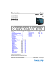
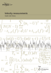
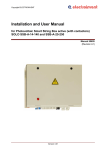
CONCEPT IQ. Installation Manual.
Control Module. Rev. 1.0 5/03
p1
Control Module 995501 / 995502
Contents
Control Module Parts List ..............................................................................................................1
Specifications .................................................................................................................................1
Installation Procedure ....................................................................................................................2
Connection Details. Zone Inputs (Detectors), Tamper switch and Fuses ................................ 3
Mode 3 Telephone line connection ..............................................................................................3
Connection Details. Power, Warning devices & LAN ................................................................. 4
Control Module Parts List
-
Control Module PCB mounted in metal enclosure.
User Manual.
Installation Manual. (This document)
Installation Kit containing: (Contents may vary outside Australia)
- 4 x Pan Head Self-tapping screws 4x6mm. Used to secure the enclosure cover.
- 5 x plastic “D” bungs. Must be fitted to all unused cable entry cutouts in the cover.
- Telecom Line cord. (Note: Non-standard configuration. Only suitable for use with this product)
- 10 x 3k3 End-of-line resistors. (orange-orange-black-brown-brown) Used for Single EOL / Dual EOL / Zone Doubling.
- 10 x 6k8 End-of-line resistors. (blue-grey-black-brown-brown) Used for Dual EOL or Zone Doubling.
- 10 x 1k End-of-line resistors. (brown-black-black-brown-brown) Used for Zone Doubling.
- Tamper switch.
- Tamper switch bracket.
- 2 x 6 Way plug-on screw terminals. (Only for PCBs that do not have fixed terminal blocks fitted)
- 1 x 3 Way plug-on screw terminals. (Only for PCBs that do not have fixed terminal blocks fitted)
- 5 x 2 Way plug-on screw terminals. (Only for PCBs that do not have fixed terminal blocks fitted)
- 2 x 6.3mm Tamper switch connectors.
- Battery connection lead, 220mm, pre-assembled.
- 1 x 2 Amp M205 (20mm) Fuse. (Spare)
Electrical Specifications
Power Supply I/P:
Power Supply O/P:
Plug pack Mains Supply:
Plug pack Output:
PCB AC Input Voltage:
Battery Capacity:
DC Operating Voltage (Batt I/P)
Battery Input Fuse (F1):
Current:
Fuse Protection (F2):
Auxiliary Outputs:
OUT1 (Strobe) / OUT2
Siren Output (SPK): Maximum Load:
NOTES:
240V AC -10% / +10%. 50 Hertz.
16V AC. 1.0 Amperes.
16V AC.
12V. 7AH. Sealed Lead Acid Battery.
9.5 to 14 V DC. (Low Battery alarm activated at 11.2V +/- 0.3V)
5 Ampere.
Total combined current required by devices connected to
“DET+” and “LAN+” must not exceed 600 milliAmps.
2 Ampere. (DET+ and LAN+)
Max. switched current = 200mA per Auxiliary. (Open Collector)
8 Ohms. (i.e. 1 x 8 Ohm Speaker only. Additional speakers must
not be connected in parallel)
1) ALWAYS REPLACE FUSES WITH THE SAME FUSE TYPE AND VALUE!
2) See data supplied with detectors and output devices for current consumption.
Mechanical Specifications
Dimensions:
Weight:
Height: 260 mm.
Width: 265 mm.
4.2 kg. (Cabinet & cover, PCB and 7AH battery)
Depth: 80 mm.
Plug pack = 0.6kg
Environmental Specifications
Continuous Operating Temperature
Storage Temperature
Relative Humidity (Non condensing)
©
2003. Inner Range Pty. Ltd.
0 to +50 °C
-20 to +70 °C
15 to 85 %
Part No: 635501V2
p2
CONCEPT IQ. Installation Manual.
Control Module. Rev. 1.0 05/03
Installation Procedure
1. Installer. The system must be installed and maintained by a competent, qualified installer who holds appropriate
licences for Telecommunications and Security System cabling in accordance with local Regulations.
2. Location. The Control Module must be installed in a secure location near an AC Power outlet and Telephone line
connection. Install the unit where it will not be subject to temperature or humidity outside the specified range, and will
not come into contact with water, other liquids, high dust levels or chemical atmospheres.
Adequate ventilation must be provided around the cabinet (50mm min.) to ensure that heat from any other source does
not cause the Control Module to operate at an unsafe temperature.
3. Positioning. Orientation of the cabinet MUST be as per the illustration below with the battery at the bottom.
Fit the Tamper switch into the hole provided in the Tamper switch bracket. The Tamper switch bracket must be
positioned in the slot provided and under the base of the cabinet, before the cabinet is secured to the wall.
When wired to the “TAMP” input, Tamper switch alarms if the cabinet is removed from the wall or the cover is opened.
4. Mounting. The cabinet must be secured to a flat, solid, vertical surface using appropriate fasteners through the 4 holes
provided in the base, and must be positioned to provide unhindered access for installation and maintenance.
The two mounting holes in the top of the cabinet are keyhole slots to assist with positioning.
When mounting onto flammable surfaces, a fire protection backplate MUST BE INSTALLED.
5. Power. (Plug Pack and cable color may vary outside Australia) Strip 5mm of insulation from the ends of the 3 Plug
pack cable conductors. Terminate the 16VAC conductors into the “AC” Input connections, and the Earth wire (Green/
Yellow) into “BATT -” on the PCB.
CAUTION: Do not connect the Plug pack to an AC outlet until all wiring is complete and checked.
6. Battery. Connect the pre-assembled battery cable into the “BATT +” and “BATT -” connections on the PCB.
CAUTION: Do not connect the Terminals to the Battery until all wiring is complete and checked.
7. Cabling. All cabling must enter the cabinet via the existing cutouts provided in the rear and sides. Additional holes
must not be cut in the cabinet. Installation of Cables both inside the cabinet, and external to the cabinet, must conform
to the appropriate Standards for Security and Telecommunications systems.
Cables must be protected at the entry points by grommets or by allowing the conduit to protrude into the cabinet.
The “D” Bungs provided must be fitted to all unused cable entry cutouts.
DO NOT connect the LAN “CLK” & “DATA” wires to the Control Module until all LAN Modules (e.g. LED Terminals) are
Commissioned.
8. Diagnostics. The “STATUS” Lamp on the Control Module can be used to assist with troubleshooting and testing.
SLOW FLASHING:
MicroProcessor OK (Running)
FAST FLASHING: Controller is Dialing.
MicroProcessor Not running, OR Programming Key Upload or Download in progress.
NOT FLASHING:
9. Cover. In order to comply with regulations the cover must always be correctly re-fitted following any installation or
maintenance work. Engage the hinges on the Left-hand side and fasten the cover tightly to the cabinet using all four (4)
of the screws provided. Screw holes are located on both edges of the two Right-hand side corners.
^
Top mounting holes (x2).
Step 4.
^
STATUS Lamp.
Step 8.
JP9. Mode 3 Line Socket
for connection to Telecom
Line. (Special cable
supplied must be used)
Port 1. Serial Comms Port.
(995502, IQ Plus only)
(Prog. Key or PC or Printer)
Port 0. Serial Comms Port.
(Prog. Key or PC)
Tamper switch bracket.
(and Battery retainer)
Step 3.
<
T1. 16V AC Power
connections. Step 5.
>
Latch for optional lock.
T3. Battery connections.
Step 6.
12V, 7AH Battery position.
Step 6.
Rear cable entry cutout.
Step 7.
Bottom Mounting Holes (x 2).
Step 4.
V
< Location of Side Cable
entries. Step 7.
CONCEPT IQ. Installation Manual.
Control Module. Rev. 1.0 5/03
p3
Connection Details. Detectors, Tamper switch and Fuses
F1. Battery Input Fuse. 1A. M205.
F2. PWR Fuse. 1A. M205.
T2. “TAMP”. Dedicated Cabinet Tamper
input. Tamper switch supplied.
No End-of-line resistors necessary.
Detector
T6 and T7. Zone Input connections.
C
EOL Res.
3k3 Typ.
Tamp.
NC
C
Alarm
NC
Detector
C
EOL Res.
3k3 Typ.
6k8 Typ.
1st Detector
C
Alarm
NC
C
Tamp.
EOL
1k
NC
EOL
3k3
NC
2nd Detector
C
NOTE:
The 1k EOL
Resistor must
be fitted at the
2nd Detector.
Tamp.
C
Alarm
6k8
NC
Tamp.
NC
C
Alarm
NC
Mode 3 Telephone Socket Wiring for Australia
1
604 Cable from
Concept IQ
(Supplied)
2
3
4
6
6
JP9
5
6
1
1
3
3
2
2
2
5
4
5
Zone Doubling.
1k
Seal
4k3
1st Zone in Alarm
7k8
2nd Zone in Alarm
11k1
1st & 2nd Zones in Alarm
Open Cct:
Tamper
Short Cct:
Tamper
NOTE: Zone Input connections.
“Normally Open” Alarm Contacts.
1
4
Control
Module
Dual End-of-Line.
e.g.
3k3
Seal
10k1
Alarm
Open Cct:
Tamper
Short Cct:
Tamper
T5. “DET+” and “0V”.
Detector Power connections.
12V Supply for Detectors and Auxiliary
Devices. Total combined current sourced
from “DET+” and “LAN+” must not exceed
600 milliAmps.
Minimum Cable spec: 14/0.2
604 Socket
to other equipment.
Single End-of-Line.
e.g.
3k3
Seal
Open Cct:
Alarm
5
6
PSTN
Line
Normally Open Alarm Contacts (e.g. As
often found on Smoke Detectors) are
wired in the same manner as Normally
Closed contacts.
When programming the Zone Input,
Option 7 (“Normally Open”) in the “Zone
Options” must be selected. (Addresses
651 [Zone 1] to 666 [Zone 16] )
p4
CONCEPT IQ. Installation Manual.
Control Module. Rev. 1.0 05/03
Connection Details. Power, Warning devices & LAN
JP10. DTMF/Voice
Card Port.
T8. “Aux LAN”.
For temporary
connection of a
Terminal for
diagnostic purposes.
T9. Zone Input /
Auxiliary Output
Expansion Bus Port.
Earth
(Grn/Yell)
4 Core Security Cable
recommended. (14/0.2)
Minimum Cable spec: 14/0.2
CAUTION:
Total current sourced from
“DET+” and “LAN+” must not
exceed 600mA.
Minimum Cable spec: 14/0.2
Siren cover Tamper
switch (Normally Closed)
Minimum Cable spec: 14/0.2
Battery cable supplied.
T4. LAN connections to Terminals. (Up to 4)
Maximum run to furthest LAN Module: 100m.
Total LAN cabling: 150m maximum.
If twisted pair cable is used, DO NOT
combine “Clock” & “Data” on the same pair.
T5. “OUT2” & “DET+”. Auxiliary 2 Output.
General purpose Aux.
May be used for Piezo Siren. e.g. Program
Aux 2 as Auxiliary Event Type 9 (Ext Siren) or
10 (Int Siren) at Address 802.
Maximum switched current: 200 mA.
T5. “OUT1” & “DET+” (Strobe)
Auxiliary 1 Output.
Normally used for Strobe. e.g. Assign
Auxiliary Event Type 1 at Address 801.
Maximum switched current: 200 mA.
T5. “SPK” & “DET+”
Siren Speaker output.
Maximum load: 8 Ohms
Minimum Speaker rating: 10 Watts.
(i.e. 1 x 8 Ohm Speaker only. Additional
speakers must not be connected in parallel)
NOTE: A 6k8 Resistor must be connected
between “SPK” & “DET+” if Siren speaker not
connected.
T3. “+” & “-”.
12V Sealed Lead Acid Battery connection.
Maximum Battery capacity: 7 AH
T1. “AC”.
16V AC Input.
(Connect Green/Yellow Earth wire to T3 “-”)
(Plug Pack and cable color may vary
outside Australia)
Port 0 & Port 1 (995502, IQ Plus only) Serial
(TTL) Comms Port, connect Prog. Key (Port
0 only), RS232 PC connection requires
adapter cable 993030 or Printer connection
(IQ Plus only) adapter cable 993030DB25.
Disclaimer: 1. The manufacturer &/or it’s agents take no responsibility for any damage, financial loss or injury caused to any equipment, property or
persons resulting from the correct or incorrect use of the system or it’s peripherals. The purchaser assumes all responsibility in the use of the system
and it’s peripherals.
2. While every effort has been made to ensure the accuracy of this manual, the manufacturer assumes no responsibility or liability for any errors or
omissions. Due to ongoing development, this manual is subject to change without notice.