1
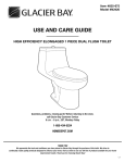
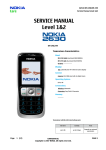
amuheat floor heating systems Laminate Panel 14 Installation Manual LP12-V1 Table of Contents Laminate Panel 14 Installation Manual Introduction 1 Laminate Panel 14 Product Important Installation Guidelines 2 Tools & Materials Needed for Installation Kit Contents Glossary of Terms Choosing Suitable Carpet & Underlay Electrical Requirements 3 Electrical Requirement Laminate Panel 14 & Sensor Rough-In Testing & Product Specification 4 Warranty Validation Floor Sensor Resistance Test Insulation Test Laminate Panel 14 Heater Specification Installation 5 Subfloor preparation Position & fix heating mat 6 Electrical connection Important Points for the Carpet Fitter Restrictions & Safety 7 Furniture Placement Restrictions & Safety Advice Risk if Carpet Discoloration Warranty 8 Warranty Install Test Record & Warranty Registration Introduction Please read carefully before proceeding with installation Laminate Panel 14 Product Amuheat Laminate Panel 14 Thin Cable Mat has been designed and developed to exceed all relevant standards, ensuring installation is quick and simple. Experienced product design ensures minimal increase to existing floor levels with an even heat across the complete floor surface. The aluminium foil that forms the outer casing of the panel is waterproof and in addition to aiding in the even spread of heat, protects the Teflon heating element which is sandwiched between the aluminium foil. The heating element is of special design using materials carefully selected for an optimum balance of performance and safety with overheat protection. The heating element connects to a 6 metre long power-supply cable which exits the heating mat from one corner. The standard range of Laminate Panel 14 is available at a nominal heat output 140 W/m² @ 230 V in a range of predetermined lengths. Laminate Panel 14 is manufactured exclusively for Amuheat, for distribution in Australia & New Zealand. For support or further installation advice, call Amuheat Support on (02) 9114 6934. Important Installation Guidelines Laminate Panel 14 is designed for installation directly under carpet on top of the underlay Laminate Panel is not designed for installation under ceramic tile, natural stone or similar hard floor coverings. Other products are available to heat these types of floor – Contact Amuheat for more information Do not install Laminate Panel 14 under rubber or foam-backed carpets. The R-value of the carpet should not be greater than 3 as these will trap in too much heat Laminate Panel 14 must not be installed under cabinets or other fittings or furniture that will be permanently installed and attached to the floor. Built-in cabinets and other furniture with solid bases must not be placed over the mats Laminate Panel 14 must not be installed on top of other in-floor radiant heating systems (for example hydronic systems) unless the other system is permanently disconnected in such a way that it cannot be inadvertently switched on while Laminate Panel 14 is also in use. Similarly, Laminate Panel must also NOT be installed on floors where radiant ceiling heating is used in the room directly below where the Laminate Panel mat is installed Laminate Panel 14 must not be installed in thinset cement, or in direct contact with a 1 cement or concrete subfloor or slab. It must always be laid on top of the carpet underlay Do not drop or rest any heavy objects or tools on the heating mat during installation. Make sure all electrical work is done by a qualified electrician and check your electrician provides a mains power supply connected via a RCD circuit Do not cut or trim the heating mat to fit into a space that is too small. Be aware of damage to the heating mat with sharp tools, seam irons and gripper/stretchers during installation Avoid foot traffic on the heating mats whilst uncovered with carpet Do NOT plug in or switch power on to the Laminate Panel 14 mat when folded or creased at any time. Laminate Panel 14 is not suited for heating stairs Multiple heating mats connect to the thermostat in parallel - the cold tail leads cannot be joined Introduction Please read carefully before proceeding with installation Tools & Materials Needed for Installation You will require the following items to install Laminate Panel 14 Scissors Adhesive/Duct Tape Cardboard or carpet scraps (to protect the heater) 2 x 20mm Conduit (one for cold tail leads & one for floor sensor) Wall box, plate or c-clip (for mounting thermostat) RCD switch on electrical board (supplied and fitted by your electrician) You may require a 20A contactor if you are installing multiple heating mats connected to one thermostat where the load capacity exceeds 16A Kit Contents Amuheat Laminate Panel 14 heater Element fault monitor Digital Programmable thermostat Floor temperature sensor Installation guide Thermostat operating guide Warranty registration Glossary of Terms B C A E A B C D E Cold tail lead (active/neutral/earth) Factory-made cold tail joint Teflon insulated twin heating conductor Floor temperature sensor Reinforced aluminium D Laminate Panel 14 Construction Choosing Suitable Carpet & Underlay Most modern tufted and woven carpets are compatible with Laminate Panel 14. Polypropylene, hessian or jute secondary backings are compatible, but rubber- or foam-backed carpets are not compatible as they trap too much heat. The carpet must be at least 6mm thick, but not more than 25mm thick. Any type of carpet underlay can be used as long as it has a density of 100kg/m3. 2 Electrical Requirements Laminate Panel 14 Electrical Requirement Before installing Laminate Panel 14 you should make allowance for the electrical connections (refer to diagram below & electrical schedule supplied with your quote/order). All electrical connections (including thermostats) must be performed by your electrician, in accordance with current AS/NZ 3000 wiring rules. Laminate Panel 14 mat heater requires a mains voltage 230/240V supply and must be connected to an approved Residual Current Device (RCD) mounted on the switchboard. It is recommended you consult with your electrician to ascertain whether or not the circuit and cabling can handle the additional load and if a RCD is protecting the circuit. If connecting multiple heating mats with an electrical load greater than 16A to one thermostat, you will require a suitably sized electrical contactor. Laminate Panel 14 & Sensor - Conduit to power supply on RCD circuit. - Flush box, plate or c-clip for thermostat (height 1200mm - 1500mm). Thermostat model AT908B - Horizontal Thermostat model AT8100V - Vertical Thermostat model AT8100H - Vertical - 20mm Conduit (max 2 heaters) & draw wire pulled through. Refer to electrical schedule for number required - 20mm Conduit for floor sensor & draw wire pulled through (recessed into subfloor) Positioned 250mm in between heating elements - Floor heating system - Floor sensor 3 Testing & Product Specification Laminate Panel 14 Warranty Validation Laminate Panel 14 is tested and supplied in good working order from our factory. To ensure the integrity of the system, an insulation and resistance test on the heating cable should be conducted before, during and after the mat heater and carpet floor installation. This information should be recorded on the Installation Test Record sheet on page 8 to validate the 5 year extended manufacturers warranty. Resistance Test This test is carried out to ensure continuity exists in the heating element. Using a multimeter on ohm setting, place one probe on the active conductor and the other on the neutral conductor (brown and blue leads on cold tail) and confirm the resistance value matches the factory test result within +/10% of the value marked on the product specification label and/or table below. Floor Sensor Resistance Test Test the thermostat floor temperature sensor as above. The range on the multimeter should be set to Auto or 20K Ohm. Resistance readings for AT8100-x thermostat sensors should be between 5-15K Ohm and AT908-x thermostat sensors should be between 100-120K Ohm. Insulation Test This test is performed to measure the insulation resistance between conductors and earth to ensure the cable insulation is not damaged. A low resistance reading indicates a damaged cable and must be repaired or replaced. The insulation resistance tester should be connected between the conductors (blue and brown cables) and the earth (braid wire). The meter should set to 500V and record a high resistance value. 140W Code LP420-14L LP420-14 LP490-14 LP560-14L LP560-14 LP630-14R LP630-14 LP700-14 LP840-14 LP980-14T LP1120-14 Mat Dimension (m) 1x3 1.5 x 2 1.4 x 2.5 1x4 2x2 1.8 x 2.5 2.3 x 2 2.5 x 2 2x3 2 x 1.4 x 2.5 2x4 Watt @ 230V 420 420 490 560 560 630 630 700 840 980 1120 Ohm Resistance +10–5% 126 126 108 94 94 84 84 75 63 54 57 4 Installation Laminate Panel 14 Step 1 - Subfloor Preparation Ensure the sub floor is structurally sound, clean and dry. To prevent damage to the mats, special attention should be given to ensure that no nails, screws, staple, tacks and the like are protruding from the sub floor before the carpet underlay is installed. Also, do not use staples to secure the carpet underlay to the sub floor. A staple can with time and movement protrude from the floor, pierce and damage the heating mat. Nails, screws or staples should not be installed close to the mats and power supply cables. Permanent fixtures, including built-in furniture, must NEVER be installed on top of the mats. Keep an accurate record of where the heat mats are installed, to assist you (and a future owner) to easily locate them when re-modelling work in the room is done at a future date. Taking a few photographs during the installation process is a good idea. Step 2 - Position & fix heating mat To avoid damage to the heat mats during installation, care must be taken so that tools with sharp edges or points are not dropped or used carelessly on top of the heat mats. Do not walk on the mats more than is absolutely necessary during installation, and do not drop or place heavy articles on the mats. Once the carpet underlay has been fitted, unroll and unfold Laminate Panel 14 completely and place it in the required position on top of the carpet underlay. NEVER CUT OR TRIM THE HEAT MAT TO FIT INTO A SPACE TOO SMALL FOR IT When positioning the heating mat on the carpet underlay, be aware of the following: Keep it at least 250mm from the edge of the area to be carpeted, (to prevent the spikes of the power stretcher damaging the heating mat when the carpet is being fitted) Ensure the 6mtr cold tail lead can reach the thermostat to which it will be connected Where possible, run the cold tail lead parallel or at right angles to walls, and avoid high-traffic areas Where possible, keep the corner where the cold tail lead enters the panel away from high traffic areas NEVER run the power supply cables under or over the panels To make your installation easier, Laminate Panel 14 can be laid either side up When fitting more than one panel in a room, the panels MUST NOT OVERLAP to avoid overheating Smooth out the heating mat and adhere the underlay with adhesive tape. Any adhesive tape will do. You will need to remove a small section of carpet underlay from under the panel at the point where the cold tail cord enters the heating mat, to prevent an unsightly lump on the carpet surface and excessive wear on that part of the heating mat. Band tape over this corner. After deciding the route the heating mats cold tail lead will take from the panel to the point of supply (where possible along the edge of the carpet underlay between the gripper and the carpet underlay), cut a channel in the carpet underlay along this route and drop the power supply cable into this and tape or glue it down to prevent it from “riding up” onto the top surface of the carpet underlay creating an unsightly lump. When installing two or more Laminate Panel 14 heat mats next to each other, the distance between the last wire on the edge of a panel, and the first wire on the edge of the next panel, has to be a minimum 100mm. The heating wires in adjacent panels cannot overlap and we recommend the use of tape across both panels in this area to ensure they will not overlap over time. 5 Installation Laminate Panel 14 Step 3 - Electrical Connection The included thermostat is supplied with a floor sensor, whose tip needs to be fixed between heating cables on the top or bottom surface of the heating mats, at least 30cm into the heated area. The sensor wire should be dropped into a channel cut out of the underlay back to the thermostat and taped down to avoid the sensor wire “riding up” onto the carpet underlay causing an unsightly lump. Before fitting the carpet, test the heating mats to ensure they are working correctly. Then connect the element fault monitor to the heating mats power cable to monitor for damage during the carpet installation. NEVER JOIN THE POWER SUPPLY CABLES UNDER THE CARPET. NO SERIAL CONNECTIONS OF ONE PANEL TO ANOTHER PANEL. NO DAISY-CHAINS. A QUALIFIED ELECTRICIAN MUST CONNECT THE POWER SUPPLY CABLES TO THE THERMOSTAT, AND CONNECT THE THERMOSTAT TO THE SUPPLY. Note These installation instructions are NOT intended to replace or supersede the installation instructions provided by the manufacturer of the carpet underlay and carpet, but to supplement them. BOTH sets of installation instructions should be complied with. In the event of any apparent contradiction between the Laminate Panel 14 instructions and the carpet & underlay instructions, contact Amuheat for clarity on how to proceed. Important Points for the Carpet Fitter Please ensure that compatible carpet underlay and carpet is being fitted. Remember that you are laying carpet over a thin electrical heating element. Extra care must be taken when working with sharp tools to avoid damage to the Laminate Panel 14 heat mat which could cause it to malfunction and fail. Ensure all cables have been channelled correctly into the carpet cushion to avoid unsightly lumps or an uneven carpet surface. Do not install nails, screws or staples in direct contact with Laminate Panel 14 heat mats and power supply cable. A staple left protruding can destroy the heating mat. When making a join (or “seam”) in the carpet, ensure that the seaming iron DOES NOT come into direct contact with the heating mat, as it will damage the panel. Wherever possible, avoid joins in the carpet over panels or use a piece of carpet or cardboard between the seam iron and heat mat. Always use a good quality ultra-wide heat-bond tape when joining carpets over heating mats Fit your carpet as normal above the panels, taking special care when working with sharp tools (power stretcher, knee-kicker, knives, scissors etc) in the vicinity of the panels and cables. 6 Restrictions & Safety Laminate Panel 14 Furniture Placement Restrictons & Safety Advice Always remember that you have a thin electrical appliance installed directly below your carpet. Essential restrictions and safety precautions are listed below: Ensure Laminate Panel 14 is connected to a supply protected with a RCD Where possible, run the cold tail lead parallel or at right angles to walls, and avoid high-traffic areas Never pierce the carpet with sharp items such as knives, pins, tacks, staples, needles and the like Never drive nails or screws through the carpet to secure furniture in position or for any other reason Never drop heavy articles onto the carpet Area rugs and oriental carpets may be placed on top of the heated carpet; but the total thickness of both carpets (ie. the wall to wall carpet plus the rug) must never exceed 40mm Never use chairs on castors directly on the carpet surface – always use a plastic “carpet protector” that is no more than 12mm thick and does not have spikes. Most commercial plastic “carpet protector” in the market will be acceptable Never place any furniture that has feet with a “footprint” of 10mm x 10mm or less on the carpet, irrespective of the weight of the furniture Never place any item with a “footprint” of 150mm x 150mm or more on the carpet, if that item is thicker than 25mm (for example, do not leave a mattress, pillow, bean bag or dog bed on the carpet) Furniture that has feet with a footprint between 10x10mm and 150x150mm must not exert a force greater than 70306 kg/m2 on the carpet surface Any bulky item of furniture on short legs (e.g. a sofa or a bed) must have a minimum of 50mm clearance between the top surface of the carpet and the underside of the furniture to allow free movement of air through that space. Do not allow bedclothes to restrict the airflow under a bed Specific items of furniture that should never be allowed onto the carpet surface: Pianos Stands for hi-fi speakers that have sharp points as feet Bookcases and similar types of furniture with closed bottoms When steam cleaning carpets, turn the power off to the floor heating and NEVER use the heating mats to dry out carpets Warning: Risk of Carpet Discoloration The major factors affecting carpet discoloration of a carpet are: the nature of the fibers the type of coloring process and it’s application to fibers, yarns, or fabric the color range from pastels to dark colors the temperature level if the heat is trapped under a high level of insulation such as a futon mattress, bean seat or a dog bed the length of time the carpet is exposed to higher temperature In our experience, Laminate Panel 14, which is powered at approximately 140W/m2 does not cause carpet discoloration when installed under the conditions of this Installation Manual, specifically the section “Restrictions & Safety”. However, if excessive insulation is placed for long periods of time over a heated carpet area, some carpets of lighter colors, and lower quality will probably be the first to be subject to discoloration. 7 Warranty Laminate Panel 14 Warranty Laminate Panel 14 is supported by a 1 year manufacturers warranty from the date of purchase. An extended 5 year manufacturers warranty is offered by registering your purchase and installation below. Where it is determined Laminate Panel 14 is defective in material, and has not been damaged as a result of misuse or misapplication, Amuheat will repair or replace the heating panel. If the repair is not feasible, Amuheat will at their discretion replace or refund the original cost of the heating panel. The warranty does not cover faults caused by incorrect design by others / misuse / damage caused by others / damage in transit / incorrect installation and any other subsequent damage that may occur. Repair / replacement will be fully chargeable if the damage is because of any of the above reasons. Amuheat disclaims any warranty not provided herein. Amuheat futher disclaims any responsibility for any consequential damages arising from ownership or use of the product, including inconvenience, loss of use and costs of operating the heating mat. The guarantee is a material warranty only and does not cover field labour. In order to validate the extended 5 year manufacturers warranty, the following conditions must be met: The Install control card & Warranty Card must be completed and returned to Amuheat within 60 days of purchase Proof of purchase will be required in the event of a claim - retain your receipt Installation is in accordance with the accompanying Installation Manual, any special written design or installation guidelines provided by Amuheat and all local and building and electrical codes The heater has been earthed and connected to a supply protected by a RCD circuit The heater is used with a thermostat or control system approved by Amuheat Install Test Record & Warranty Registration Complete form below and mail to Amuheat, PO Box 975, North Ryde BC 1611 or fax copy to (02) 8211 5180. Installer Name Phone Email Owner Name Address Phone Email Purchase Detail Date of purchase Heater Install Test Records Heater Model Test Continuity Resistance (Ohms) Insulation Resistance (Mohms) Invoice Number Installation Date Before Install After Install After Floor Install 8 amuheat floor heating systems © 2012 Amuheat Pty Limited Lg1 64 Talavera Road Macqaurie Park NSW 2113 PO Box 975 North Ryde BC NSW 1611 Tel: (02) 9114 6934 Fax: (02) 8211 5180 [email protected] www.amuheat.com.au