1
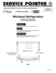
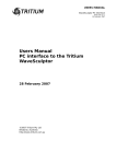
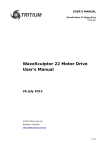
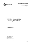
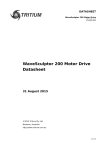
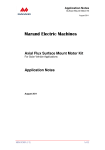
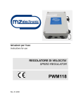
USER'S MANUAL
Precharge / Discharge Controller
TRI72.001 ver 1
19 January 2007
Precharge / Discharge Controller
User's Manual
19 January 2007
©2007 Tritium Pty Ltd
Brisbane, Australia
http://www.tritium.com.au
1 of 12
USER'S MANUAL
Precharge / Discharge Controller
TRI72.001 ver 1
19 January 2007
TABLE OF CONTENTS
1
2
3
3.1
3.2
3.3
3.4
3.5
3.6
4
5
6
7
8
9
10
11
Introduction................................................................................................ 3
Operating Overview................................................................................... 4
Front Panel................................................................................................. 5
Connections............................................................................................. 5
Power Input.............................................................................................. 6
Main Contactor Output............................................................................. 6
Precharge Contactor Output.................................................................... 6
Precharge LED.......................................................................................... 6
Discharge LED.......................................................................................... 7
Rear Panel.................................................................................................. 7
External Contactors.................................................................................... 7
Connections – type 1.................................................................................. 8
Connections – type 2................................................................................ 10
Safety....................................................................................................... 11
Front Panel Connector Pinouts................................................................. 11
Rear Panel Connector Pinout.................................................................... 12
Revision Record....................................................................................... 12
2 of 12
USER'S MANUAL
Precharge / Discharge Controller
TRI72.001 ver 1
19 January 2007
1
INTRODUCTION
This document details the interface, installation and usage requirements
for the Tritium Precharge / Discharge controller.
The Precharge / Discharge controller provides a safe way to connect and
disconnect a WaveSculptor motor controller (or any other capacitive load
of a similar size) to a low-impedance power source such as a battery
pack, without the risk of dangerous currents, contact welding, or sparks.
For operating limits and specifications, please refer to the Precharge /
Discharge controller datasheet (TRI72.002), available on the Tritium
website.
For further details on overall system configuration, please refer to the
Wiring Engineering Reference document (TRI50.010), available on the
Tritium website.
3 of 12
USER'S MANUAL
Precharge / Discharge Controller
TRI72.001 ver 1
19 January 2007
2
OPERATING OVERVIEW
The precharge controller provides two basic functions:
1) Charges the DC bus capacitors in the motor controller in a
controlled manner when power is applied to the system, to avoid
high inrush currents.
2) Slowly discharges the DC bus capacitors when power is removed,
to avoid a shock hazard when disconnecting the motor controller.
The precharge function is accomplished by first connecting the Bus+
terminal of the motor controller to the Battery+ terminal through a
resistor, to limit current flow. Precharge time is determined by the RC
time constant of the circuit. Once the two voltages are close then the
two terminals are connected directly.
The discharge function is accomplished by disconnecting the Bus+ motor
controller and Battery+ terminals, then connecting a resistor between
Bus+ and Battery Ground to discharge the capacitors in the motor
controller. Discharge time is determined by the RC time constant of the
circuit. Note that depending on the resistances used, the discharge time
may be different from the precharge time.
The precharge controller also provides protection for itself in the event of
a fault in the main circuit.
It operates subject to an acceptable
temperature on the internal heatsinking. This heatsinking is absorbing
the energy dissipated in the precharge and discharge resistors (nominally
128 Joules for a standard Wavesculptor). During normal operation, the
heatsink will have only a minimal increase in temperature. However, if
the output of the precharge circuit (the WaveSculptor, or other attached
circuitry) has a fault, and there is a short or low-impedance connection
between the output terminals, then the precharge resistor will rapidly
become hot and the circuit will shut itself down.
4 of 12
USER'S MANUAL
Precharge / Discharge Controller
TRI72.001 ver 1
19 January 2007
3
FRONT PANEL
The following diagram shows the connections and status LEDs on the
front panel of the precharge controller. The three connectors (power,
main contactor, precharge contactor) are all 2-way Molex Mini-Fit Jr male
connectors.
Discharge LED (Red)
Precharge LED (Red)
Precharge Contactor Output
Output On LED (Blue)
Main Contactor Output
Power LED (Green)
12V input power
3.1
CONNECTIONS
Due to the possibility of the customer using various different wire sizes,
Tritium does not supply mating housings or crimps for these connectors.
The following part numbers (from Digikey) are suitable.
For reliable connections, please use one of the recommended crimp tools
– do NOT use pliers.
Description
Order Code
Price (US$)
18-24 AWG Mini-Fit Jr Female crimp (MOQ = 10)
WM2501-ND
$0.10
22-28 AWG Mini-Fit Jr Female crimp (MOQ = 10)
WM2503-ND
$0.07
2 way crimp housing
WM3700-ND
$0.46
6 way crimp housing
WM3702-ND
$0.61
Mini-Fit Jr dedicated prototype crimp tool
WM9996-ND
$243.27
Generic Molex crimp tool
WM9999-ND
$50.75
5 of 12
USER'S MANUAL
Precharge / Discharge Controller
TRI72.001 ver 1
19 January 2007
3.2
POWER INPUT
The power input provides power to operate the circuit and the external
contactors, and is also the control signal for precharge / discharge
operation.
When voltage is present on this input, the Green “Power” LED will be
illuminated. The circuit will begin precharge operations. When power is
removed from this input, the Green LED will go dark, and the circuit will
begin discharge operations.
The power to this connection should be routed though a key switch near
the driver (or a relay controlled via CAN bus from the driver controls) and
also through an emergency shutdown switch, accessable from either (or
both) the driver and outside the vehicle. Please refer to the relevant
regulations for further details.
3.3
MAIN CONTACTOR OUTPUT
The Main contactor output provides a controlled on/off power supply to
operate an external high voltage DC contactor in the main power path.
The status of this output is indicated on the Blue “Output ON” LED.
This output will come on automatically as soon as voltage is applied to
the power input connection of the precharge controller. It will turn off if
the internal heatsinking rises to the temperature cut-off point, and will
then turn back on when the heatsinking falls back to an acceptable level.
The voltage present on this output (when switched on) will be whatever
voltage is provided to the power input connection. Please choose an
external contactor that operates with a control voltage in this range.
3.4
PRECHARGE CONTACTOR OUTPUT
The Precharge contactor output provides a controlled on/off power supply
to operate an external high voltage DC contactor in the main power path.
This output will come on only when the voltage on the battery (precharge
input) and the voltage on the Wavesculptor (precharge output) are
closely matched. It is also affected by the temperature of the internal
heatsinking in the same manner as the main contactor output.
The voltage present on this output (when switched on) will be whatever
voltage is provided to the power input connection. Please choose an
external contactor that operates with a control voltage in this range.
3.5
PRECHARGE LED
The Red “Precharge” LED indicates that the voltage on the battery and
the voltage on the Wavesculptor are not yet matched. During normal
operation, it should illuminate for a limited time only, 1.5 seconds for a
Type 1 circuit, and 25 seconds for a Type 2 circuit. Illumination for longer
periods than this indicates that there is a short-circuit fault on the output.
6 of 12
USER'S MANUAL
Precharge / Discharge Controller
TRI72.001 ver 1
19 January 2007
The precharge controller will shut down under these circumstances to
protect both itself and the output device.
3.6
DISCHARGE LED
The Red “Discharge” LED indicates that the circuit is actively discharging
the capacitors in the Wavesculptor, and that a dangerous voltage is still
present on the output connections. It illuminates when there is a voltage
across the 680 ohm discharge resistor.
4
REAR PANEL
The following diagram shows the connections on the rear panel of the
precharge controller. The single connection (voltage sense) is a 6-way
Molex Mini-Fit Jr male connector.
Voltage Sense Connection
Please refer to the following sections (Type 1 & Type 2 connections) for
further information regarding this connector.
5
EXTERNAL CONTACTORS
External contactors must be used in this circuit to switch the high voltage
and high currents present in the Battery to WaveSculptor connection.
Make sure that the contactors chosen can interrupt expected fault
currents. The decision on what contactors to use should also depend on
the type and rating of battery pack fusing, wiring, and internal
resistances.
Tritium recommends the use of Tyco EV200 AAA NA contactors, available
from Newark, order code 09J3878, rated to 500A carry current, 2000A
break current, and up to 900V operating voltage.
7 of 12
USER'S MANUAL
Precharge / Discharge Controller
TRI72.001 ver 1
19 January 2007
6
CONNECTIONS – TYPE 1
The precharge controller can be used in two different configurations,
depending on the cost, complexity, performance and safety tradeoffs you
wish to make in your application.
This section of the document details how to configure the precharge
controller for a fast precharge time of approximately 1.5 seconds, using a
moderately complex system with two external DC contactors. This
system will be referred to as a “Type 1” system throughout this
document.
The following diagram shows an overview of the connections used in a
Type 1 system. The pin numbers shown are for the 6-way voltage sense
connector on the rear panel of the precharge controller.
MAIN CONTACTOR
PRECHARGE CONTACTOR
FROM BATTERY PACK (+)
TO WAVESCULPTOR (+)
Pin 1
Pin 6
Pin 3
PIn 2 = No Connect
Pin 5 = No Connect
47 ohms
12V Operating Power
Vehicle Ground
Fault Detection
and control logic
680 ohms
Pin 4
TRI72 Precharge / Discharge controller
FROM BATTERY PACK (-)
TO WAVESCULPTOR (-)
In this circuit, the sequence of events for precharge under normal
operating conditions is as follows:
1) 12V operating power applied, Green LED on
2) Internal relay disconnects 680 ohm resistor
3) Main contactor energises, Blue LED on
4) WaveSculptor charges through 47 ohm resistor, Precharge LED on
5) Voltages on Battery and Wavesculptor match, Precharge LED off
6) Precharge contactor energises
7) WaveSculptor is ready for operation
8 of 12
USER'S MANUAL
Precharge / Discharge Controller
TRI72.001 ver 1
19 January 2007
The sequence for discharge operations is as follows:
1) 12V operating power removed, Green LED off
2) Precharge and Main contactors disengage, Blue LED off
3) Internal relay closes and connects 680 ohm resistor to ground
4) WaveSculptor discharges through 680 ohms, Discharge LED on
5) Low voltage reached, Discharge LED off
The following diagram illustrates a typical system using a Type 1
configuration:
WaveSculptor Motor Controller
Part: TRI50
Precharge/Discharge Controller
Part: TRI72
Anderson Power Products 50A connector
Part: SB50
Anderson Power Products 50A connector
Part: SB50
To Battery Pack / HV DC bus
500A 900V DC contactor
Part: EV200 AAA NA
'Precharge' contactor
500A 900V DC contactor
Part: EV200 AAA NA
'Main' contactor
9 of 12
USER'S MANUAL
Precharge / Discharge Controller
TRI72.001 ver 1
19 January 2007
7
CONNECTIONS – TYPE 2
The precharge controller can be used in two different configurations,
depending on the cost, complexity, performance and safety tradeoffs you
wish to make in your application.
This section of the document details how to configure the precharge
controller for a slow precharge time of approximately 25 seconds, using a
simple system with one external DC contactor. This system will be
referred to as a “Type 2” system throughout this document.
The following diagram shows an overview of the connections used in a
Type 2 system. The pin numbers shown are for the 6-way voltage sense
connector on the rear panel of the precharge controller.
PRECHARGE CONTACTOR
FROM BATTERY PACK (+)
TO WAVESCULPTOR (+)
Pin 5
Pin 3
Pin 1 = Tie to Pin 2
Pin 2 = Tie to Pin 1
Pin 6 = No Connect
5A Fuse
12V Operating Power
Vehicle Ground
Fault Detection
and control logic
680 ohms
Pin 4
TRI72 Precharge / Discharge controller
FROM BATTERY PACK (-)
TO WAVESCULPTOR (-)
In this circuit, the sequence of events for precharge under normal
operating conditions is as follows:
1) 12V operating power applied, Green LED on, Blue LED on
2) Internal relay connects 680 ohm resistor between pin 5 and pin 3
3) WaveSculptor charges through 680 ohm resistor, Precharge LED on
4) Voltages on Battery and Wavesculptor match, Precharge LED off
5) Precharge contactor energises
6) WaveSculptor is ready for operation
The sequence for discharge operations is the same as for a Type 1 circuit.
10 of 12
USER'S MANUAL
Precharge / Discharge Controller
TRI72.001 ver 1
19 January 2007
8
SAFETY
If any LEDs on the front of the precharge controller are illuminated, then
the output is potentially at a high voltage and in an unsafe state.
Always treat any high voltage connection as potentially live. Do not rely
on the LED indicators of the precharge controller for notification of a live
connector, as a LED or part of the circuit responsible for driving it may
have failed.
9
FRONT PANEL CONNECTOR PINOUTS
The following diagram shows the connector pinouts as viewed when
looking at the precharge controller, ie the view you have when inserting
crimps into the rear of the connector housing.
Precharge -
Ground
Precharge +
Main +12V
Main +
11 of 12
USER'S MANUAL
Precharge / Discharge Controller
TRI72.001 ver 1
19 January 2007
10
REAR PANEL CONNECTOR PINOUT
The following diagram shows the connector pinout as viewed when
looking at the precharge controller, ie the view you have when inserting
crimps into the rear of the connector housing.
Pin 5: Battery Input 2
Pin 6: Centre Tap Input
Pin 4: Battery Ground
Pin 3: Controller Input
Pin 1: Battery Input 1
Pin 2: Battery Input 2
11
REVISION RECORD
WHO
DATE
CHANGE
JMK
19 January 2007
Version 1 - Initial Document
12 of 12