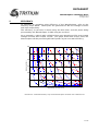
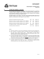
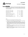
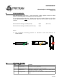
1
DATASHEET
WaveSculptor 200 Motor Drive
TRI74.015 ver 4
31 August 2015
WaveSculptor 200 Motor Drive
Datasheet
31 August 2015
©2015 Tritium Pty Ltd
Brisbane, Australia
http://www.tritium.com.au
1 of 12
DATASHEET
WaveSculptor 200 Motor Drive
TRI74.015 ver 4
31 August 2015
TABLE OF CONTENTS
1
Introduction........................................................................................3
2
DC Bus...............................................................................................4
3
Motor Output......................................................................................5
4
Motor Sense.......................................................................................6
5
Efficiency............................................................................................ 7
6
Operating Power & Cooling..................................................................9
7
Control & Telemetry Interface............................................................10
8
Mechanical.......................................................................................11
9
Environmental...................................................................................12
10
Revision Record................................................................................12
2 of 12
DATASHEET
WaveSculptor 200 Motor Drive
TRI74.015 ver 4
31 August 2015
1
INTRODUCTION
This document describes the specifications, performance and properties of the
Tritium WaveSculptor 200 Motor Controller.
For more details on communications, mechanical positioning and mounting,
wiring and precharge, cooling, and installation, please refer to the User's Manual
document available on the Tritium website.
Operating the controller beyond the limits specified in this document will result in
the voiding of the controller warranty. Tritium accepts no responsibility for
events caused as a result of operating the controller beyond the limits specified
in this document. Note that the specifications in this document are subject to
change at any time due to product improvement.
3 of 12
DATASHEET
WaveSculptor 200 Motor Drive
TRI74.015 ver 4
31 August 2015
2
DC BUS
The DC bus connection provides power to the controller during normal (motoring)
operation, and accepts power from the controller during regenerative braking
operation. It is expected to be connected to a battery pack through a precharge
circuit and a fuse.
Continuous bus voltage minimum:
0
V
(Note 1)
Continuous bus voltage maximum:
450
V
Instantaneous bus voltage maximum:
475
V
(Note 2)
Instantaneous bus current maximum (drive):
368
A
(Note 3, 4)
Instantaneous bus current maximum (regen):
-368
A
(Note 3, 4)
DC bus capacitance
800
µF
Notes:
1.
The WaveSculptor control electronics operate from low-voltage DC supplied
along the CAN bus cable, not from the high-voltage DC bus. Therefore, the
supply to the main power stage (via the DC bus) has no operating minimum
voltage.
2.
The WaveSculptor uses 600V IGBTs as the power switching elements.
Exceeding this voltage across the device for even a short interval will result
in catastrophic failure of the motor controller. The WaveSculptor contains
sufficient internal capacitance, and sufficiently rapid detection circuitry, such
that it can protect itself against a self-imposed worst-case situation during
normal operation. This situation is regenerative braking at full current, at
maximum continuous bus voltage, and having the DC bus connection broken
or removed. This situation can occur as a result of the DC bus protection
contactor opening, the battery fuse blowing, or a loose connection in the
vehicle wiring. Operating with higher DC bus voltages than the continuous
voltage maximum could result in this self-protection mechanism failing to
shut down the controller in time, resulting in the destruction of the controller.
3.
The instantaneous current rating of the DC bus is related to the highest
power drive situation, which is driving at full motor current and full speed. In
this case, the bus current will be √3 / √2 * RMS motor current maximum
(300A), giving a current of 368A DC. The equivalent factors apply for
regenerative braking. Although the controller is capable of processing this
bus current, the motor impedance (power factor) will limit the current at high
speed, therefore limiting the bus current.
Modelling of your motor
impedance in the drive system should be performed to calculate peak power.
4.
The maximum DC bus current can be limited by the WaveSculptor under
software control, and is adjustable dynamically via a command on the CAN
bus during operation to anywhere between 0 and 100% of full current. This
feature can be used to limit the current capability and sizing of battery
packs, battery wiring, battery fusing, and contactors.
4 of 12
DATASHEET
WaveSculptor 200 Motor Drive
TRI74.015 ver 4
31 August 2015
3
MOTOR OUTPUT
The motor output connection provides three-phase power to the motor during
normal (motoring) operation and receives power during regenerative braking. It
is expected to be connected to a three-phase motor, either an induction or BLDC
(permanent magnet) type.
Instantaneous motor current maximum:
300
Arms
(Note 5)
Output voltage maximum (at max DC bus):
320
Vrms line-line
Motor phase inductance minimum:
50
µH
(Note 6, 8)
Motor resistance minimum:
0
Ω
(Note 7, 8)
Notes:
5.
The motor current limit is software controlled and may be limited to lower
values via the configuration / setup utility if required.
6.
The WaveSculptor requires a minimum amount of inductance in each motor
phase to properly regulate current. Not providing this inductance may result
in an out-of-regulation condition of the motor current control loop, possibly
resulting in an undesired self-protection shutdown, or failure of the
controller. Please ensure that both the motor inductance, and any external
inductors (if used), are still providing at least the minimum required
inductance, even at full rated current, and at elevated temperatures.
7.
As long as the minimum inductance per phase requirement is met, the
WaveSculptor will regulate current and operate successfully into a shorted
connection.
8.
The WaveSculptor can report inductance and resistance present on it’s
output when running the configuration / setup program. This will provide a
figure for the complete output circuit, including motor, external inductors (if
any), wiring, and connectors. This can be used to verify these values meet
the datasheet requirements, but only for low current operation, as the test is
performed using a current of approximately 20A.
5 of 12
DATASHEET
WaveSculptor 200 Motor Drive
TRI74.015 ver 4
31 August 2015
4
MOTOR SENSE
When driving an AC Permanent Magnet motor, the WaveSculptor requires three
sensors from the motor to give position feedback at low velocities. When driving
an induction motor, the WaveSculptor requires a motor shaft encoder to give
velocity feedback. Motor temperature can also be measured for both telemetry
data and motor protection, if desired.
Sensor power supply output 1:
5
V
(Note 9)
Sensor power supply output 2:
12
V
(Note 9)
Sensor power supply current maximum:
100
mA
Sensor power supply isolation:
1000
V
(Note 10)
BLDC motor position sensor input phase offset:
±10
°
(Note 11, 12)
Induction motor encoder resolution minimum:
64
ppr
(Note 13)
NTC Temperature sensor at 25°C:
100
kΩ
(Note 14)
Notes:
9.
The WaveSculptor provides isolated voltage supplies to operate the motor
position sensors and motor temperature sensor. These supplies are a
regulated 5V and a regulated 12V output. Please check with your motor
supplier for the acceptable operating voltage of the position sensors used in
your motor.
10. The sensor output supply, position inputs, and temperature input have an
isolation barrier between them and both the DC bus and the CAN bus
voltages.
11. Motor position sensors are only required when driving a AC Permanent
Magnet motor. Motor position sensors should be aligned such that the phase
angle offset between each sensor’s output changing state, and the zerocrossing point of it’s approprate motor phase, is no more than the specified
maximum. This implies that the sensors are 120° offset (electrically, per
motor pole) from each other under ideal conditions.
12. The polarity and arrangement of the position input signals does not matter.
The WaveSculptor detects relative alignment of position signals to motor
phases, as well as the polarity of each input, when the Phasorsense
algorithm is run during motor controller configuration and setup. The
WaveSculptor can store this information for multiple motors, thus allowing
motor changes in your vehicle without having to re-run the configuration
program. Please refer to the communications and programming Appendix in
the User's Manual for more information.
13. The motor shaft encoder is only required when driving a induction motor.
14. The WaveSculptor expects a 100kΩ (at 25°C) NTC thermistor embedded in
the motor to detect motor temperature. The thermistor B model constants
(available in the thermistor datasheet) can be programmed into the
WaveSculptor during configuration / setup to exactly match the temperature
response of your thermistor.
6 of 12
DATASHEET
WaveSculptor 200 Motor Drive
TRI74.015 ver 4
31 August 2015
EFFICIENCY
To estimate an operating point efficiency of the WaveSculptor, refer to the
efficiency maps below. These plots are generated for DC bus voltages of 450V
and 200V respectively.
The efficiency (in percent) is shown using the blue lines, and the power being
processed by the WaveSculptor (in kW) using the red lines.
As an example, a vehicle with a 450V DC bus may operating at 250 Vrms output
voltage and 150 Arms output current. The graph shows that at this point, the
WaveSculptor will be processing 65 kW of power at just over 98% efficiency.
300
250
200
Output current (Irms)
5
150
100
50
0
0
50
100
150
200
Output voltage, line to line (Vrms)
250
300
Illustration 1: Predicted efficiency map of the WaveSculptor controller with a 450V DC bus
7 of 12
DATASHEET
WaveSculptor 200 Motor Drive
TRI74.015 ver 4
31 August 2015
300
250
Output current (Irms)
200
150
100
50
0
0
20
40
60
80
Output voltage, line to line (Vrms)
100
120
140
Illustration 2: Predicted efficiency map of the WaveSculptor controller with a 200V DC bus
These efficiency maps were generated using an accurate mathematical model of
the WaveSculptor’s power stage, with individual loss components confirmed
using laboratory testing.
8 of 12
DATASHEET
WaveSculptor 200 Motor Drive
TRI74.015 ver 4
31 August 2015
6
OPERATING POWER & COOLING
The maximum instantaneous output power from the WaveSculptor is limited by
internal hardware restrictions, as detailed in previous sections. However, the
continuous power capability of the controller is limited by thermal performance,
and is therefore affected by conditions external to the controller such as ambient
temperature and cooling system performance.
The WaveSculptor 200 is water cooled, and uses an external radiator with fans to
provide cooling for the system. Careful consideration should be paid to the
position and ventilation of the radiator in your vehicle.
Maximum instantaneous power output:
165
kVA
(Note 15)
Maximum continuous power output at 30°C ambient:
107
kVA
(Note 16)
Maximum continuous power output at 40°C ambient:
91
kVA
(Note 16)
Maximum continuous power output at 50°C ambient:
76
kVA
(Note 16)
Acceptable metallic cooling system components:
Aluminium
(Note 17)
Coolant pressure maximum:
0.75
(Note 18)
Bar
Notes:
15. Maximum software current limit multiplied by maximum DC bus voltage limit.
16. The controller is thermally limited to maintain the junction temperature of
the main silicon devices below 100°C. Stated figures are with Tritium
specified cooling system components with fan-forced airflow. Refer to the
User's Manual for recommended components.
17. To prevent dissimilar metal corrosion problems, all items in the liquid cooling
loop must be either plastic or aluminium. Note specifically that many
automotive radiators are copper, and must not be used. Please use only the
components recommended by Tritium, as specified in the User's Manual.
18. To avoid exceeding this pressure, it is recommended to use a pump with a
maximum head of less than this value. The Koolance PMP-400 pump
recommended in the User's Manual meets this requirement.
9 of 12
DATASHEET
WaveSculptor 200 Motor Drive
TRI74.015 ver 4
31 August 2015
7
CONTROL & TELEMETRY INTERFACE
The WaveSculptor receives commands, and transmits telemetry values, using a
CAN bus connection. No other interface is provided. Low-voltage DC power must
be provided along the CAN bus cable to operate the control electronics of the
WaveSculptor.
CAN bus supply voltage minimum:
9
V
(Note 19)
CAN bus supply voltage maximum:
15
V
(Note 19)
CAN bus supply voltage nominal:
13.8
V
(Note 19)
CAN bus supply power maximum:
20
W
CAN bus data rate maximum:
1000
kbps
(Note 20)
CAN bus isolation:
1000
V
(Note 21)
Notes:
19. Tritium recommends providing the CAN bus supply with 13.8V, using a
DC/DC converter and a backup lead-acid battery. This arrangement, when
properly implemented, gives a supply that can tolerate failures and still
operate the controller successfully for a short period of time.
20. The data rate used for CAN bus activity is set during configuration and setup
of the controller. Factory default for all Tritium devices is 500 kbits per
second.
21. The CAN bus data connection and power supply are isolated from the highpower DC bus to this continuous voltage rating. Please refer to the isolation
section in the User's Manual regarding recommended earthing and
connection practices.
10 of 12
DATASHEET
WaveSculptor 200 Motor Drive
TRI74.015 ver 4
31 August 2015
8
MECHANICAL
The WaveSculptor controller is mounted into position using three rubber mounted
M6 shoulder bolts. All dimensions in this section are with the controller mounted
in position on a horizontal surface. For full details regarding positioning and
fixing of the WaveSculptor, please refer to the User's Manual document available
on the Tritium website.
WaveSculptor enclosure length:
500
mm
(Note 22)
WaveSculptor enclosure width:
172
mm
(Note 22)
WaveSculptor enclosure height:
82
mm
(Note 22)
WaveSculptor mass:
8.5
kg
(Note 23)
Conduit size for DC and motor cables:
40
mm
(Note 24)
Conduit size for CAN bus cables:
25
mm
(Note 24)
Tubing size (ID) for coolant connections:
10
mm
(Note 25)
HV electrical terminal thread:
M8
HV electrical fastening torque maximum:
12
(Note 26)
Nm
(Note 26)
Notes:
22. Dimensions do not include attached cabling and connectors.
23. Weight includes conduit adapters, nuts and washers for high current terminal
connections, and coolant completely filling the waterblock.
24. DC (battery) and AC (motor) cabling should be contained in orange flexible
conduit. CAN bus cabling should be contained in white flexible conduit. PVC
adapters (supplied with the controller) are threaded into the front panel of
the motor controller, and the conduit should be glued into these adapters
using standard plumbing type solvent cement to fully waterproof the cable
entry points.
25. The WaveSculptor is supplied with swivelling nozzles sized for watercooling
tubing with a 10mm ID and 13mm OD. Refer to the User's Manual for
recommended components.
26. The WaveSculptor has permanently fitted threaded studs in the connection
busbars. The correct fastening hardware to use with these busbars is
detailed in the User's Manual.
11 of 12
DATASHEET
WaveSculptor 200 Motor Drive
TRI74.015 ver 4
31 August 2015
9
ENVIRONMENTAL
The WaveSculptor controller is environmentally sealed against water and dust
ingress, when mounted according to the User's Manual.
To reach the specified IP rating, please note that the conduit fittings on the front
of the WaveSculptor must be permanently glued to the conduit, using a PVC
cement.
Environmental rating (conduit glued):
IP65
Environmental rating (conduit push-fit only):
IP54
(Note 27)
Notes:
27. The acceptable mounting positions as detailed in the User's Manual are
shown below:
ü û
ü
10
REVISION RECORD
REV
DATE
CHANGE
1
12 April 2010
Document creation (JMK/MSM)
2
10 December 2010
Updated for v2 (production) hardware (JMK)
3
26 April 2011
Added bus capacitance number, revised max coolant pressure
and minimum encoder count (JMK)
4
31 August 2015
Updated figures for new waterblock coolant fixture locations
(AKR)
12 of 12