1
Watchdog Operation
User Manual
www.motium.com.au
Revision History
Rev
Data
Changes
DRN
0.0
8 Jul 08
Initial release.
AW
0.2
1 Jun 09
Preliminary release.
AW
CHK
APP
Motium is a registered trademark of Motium Pty Ltd.
Intel, Pentium, Celeron M, Core Duo, Core 2 Duo and Atom are registered trademarks of Intel Corporation.
Microsoft Windows is a registered trademark of Microsoft Corporation.
All other product names or trademarks are properties of their respective owners.
Document Number:
Whilst every care has been taken in the preparation of this document, inaccuracies due to typographical or other
errors may be present. No warranty of accuracy or reliability is given in relation to any advice or information
contained in this document and no responsibility for any loss or damage whatsoever arising in any way for any
representation, act or omission whether express or implied (including responsibility to any person by reason of
negligence) is accepted by Motium Pty Ltd (Motium) or any officer, agent or employee of Motium.
Motium reserves the right to alter the specifications of this product at any time, without prior notice.
This document is copyright and all rights are reserved. This document may not, in whole or part, be copied,
photocopied, reproduced, translated or reduced to any electronic medium or machine readable form without the
prior consent, in writing, from Motium.
Copyright © 2009 Motium Pty Ltd.
2
Watchdog Operation User Manual
Table of Content
1.
2.
Rev 0.2 – Preliminary
Watchdog operation ............................................................................................. 5
1.1.
Watchdog terminology definitions.............................................................. 5
1.2.
Runtime Watchdog .................................................................................... 6
1.2.1. Runtime Watchdog Modes.................................................................. 6
1.2.2. Watchdog Timing Diagram ................................................................. 6
1.2.3. Watchdog Events................................................................................ 7
1.3.
POST Watchdog ........................................................................................ 8
1.4.
Watchdog Configuration, Initialization, and Lifetime.................................. 8
1.4.1. Watchdog Configuration via the CMOS Setup Utility.......................... 8
1.4.2. Watchdog Configuration via the CGOS API ....................................... 8
1.4.3. Initialization and Lifetime..................................................................... 8
1.5.
Watchdog Triggering ................................................................................. 9
1.5.1. Watchdog Triggering via the CGOS API ............................................ 9
1.5.2. External Trigger Method ..................................................................... 9
1.6.
Notes and cautions .................................................................................... 9
1.7.
1.7. BIOS configuration............................................................................ 11
1.7.1. 1.7.1. ACPI Configuration submenu ................................................. 11
1.7.2. 1.7.2. Watchdog Configuration Submenu......................................... 11
CGOS API............................................................................................................. 13
2.1.
Installing the CGOS API .......................................................................... 13
2.1.1. Microsoft Windows NT/2000/XP/XP embedded/Vista ...................... 14
2.2.
Additional Programs ................................................................................ 14
2.2.1. CGOSDUMP ..................................................................................... 14
2.2.2. CGOSMON ....................................................................................... 14
2.2.3. CGOSUNINST .................................................................................. 14
2.3.
Programming ........................................................................................... 15
2.3.1. Installing the DLL .............................................................................. 15
2.3.2. Obtaining access to the processor module....................................... 16
2.3.3. Generic Board Functions .................................................................. 16
2.3.4. Watchdog .......................................................................................... 18
2.3.4.1. Mode........................................................................................ 18
2.3.4.2. Operation Modes..................................................................... 18
2.3.4.3. Events...................................................................................... 19
2.3.4.4. Stages ..................................................................................... 19
2.3.4.5. Watchdog Types ..................................................................... 20
2.3.4.6. Information Structure............................................................... 20
2.3.4.7. Configuration ........................................................................... 21
2.3.4.8. Triggering ................................................................................ 22
2.3.4.9. Disabling the Watchdog .......................................................... 22
2.4.
CGOS Library API Programmer's Reference .......................................... 23
2.4.1.1. Return Values.......................................................................... 23
2.4.1.2. Board Classes ......................................................................... 23
2.4.1.3. Information Structures ............................................................. 23
2.4.1.4. Unit numbers ........................................................................... 23
Watchdog Operation User Manual
3
2.4.2. Function Group CgosLib*.................................................................. 25
2.4.2.1. CgosLibGetVersion ................................................................. 25
2.4.2.2. CgosLibInitialize ...................................................................... 25
2.4.2.3. CgosLibUninitialize.................................................................. 25
2.4.2.4. CgosLibIsAvailable.................................................................. 25
2.4.2.5. CgosLibInstall .......................................................................... 25
2.4.2.6. CgosLibGetDrvVersion............................................................ 26
2.4.2.7. CgosLibGetLastError............................................................... 26
2.4.2.8. CgosLibSetLastErrorAddress.................................................. 26
2.4.3. Function Group CgosBoard*............................................................. 27
2.4.3.1. CgosBoardCount..................................................................... 27
2.4.3.2. CgosBoardOpen...................................................................... 27
2.4.3.3. CgosBoardOpenByName........................................................ 28
2.4.3.4. CgosBoardClose ..................................................................... 28
2.4.3.5. CgosBoardGetName ............................................................... 29
2.4.3.6. CgosBoardGetInfo................................................................... 29
2.4.3.7. CgosBoardGetBootCounter .................................................... 29
2.4.3.8. CgosBoardGetRunningTimeMeter .......................................... 30
2.4.4. Function Group CgosWDog* ............................................................ 30
2.4.4.1. CgosWDogCount..................................................................... 30
2.4.4.2. CgosWDogIsAvailable............................................................. 30
2.4.4.3. CgosWDogTrigger................................................................... 30
2.4.4.4. CgosWDogGetConfigStruct .................................................... 31
2.4.4.5. CgosWDogSetConfigStruct..................................................... 31
2.4.4.6. CgosWDogSetConfig .............................................................. 31
2.4.4.7. CgosWDogDisable .................................................................. 32
2.4.4.8. CgosWDogGetInfo .................................................................. 32
4
Watchdog Operation User Manual
1.
Watchdog operation
This chapter describes the operation of the Watchdog timer.
1.1.
Watchdog terminology definitions
The following is the definitions for the terminology used within this document.
Watchdog
A Watchdog is a combination of system means that
support automatic recovery from an error condition such
as deadlocks and system hang-ups.
Watchdog Timeout
A Watchdog Timeout defines the time period after which
the Watchdog generates a Watchdog Event if there is no
longer a response from the system.
Watchdog Event
If there is no system response within a defined time
period, then the Watchdog generates a Watchdog Event.
Usually this is a hardware signal such as a non-maskable
interrupt or a reset signal.
Watchdog Trigger
This is the system response that forces the Watchdog to
reload its timeout counter, i.e. triggering the Watchdog
prevents a Watchdog Event.
BIOS Power On Self Test (POST)
This is the amount of time needed for system initialization
between power-up and the start of the loading of the
operating system.
Rev 0.2 – Preliminary
Runtime
The phase of normal system operation starting with the
loading of the operating system, i.e. after the POST has
finished.
CMOS Setup Utility
This is the system configuration tool built into the BIOS. It
controls the CMOS RAM used to save the system
configuration.
Watchdog Operation User Manual
5
1.2.
Runtime Watchdog
The Runtime Watchdog is available during normal system operation and is used to
recover from malfunctioning operating systems, application software or system
expansions like add-in hardware or peripheral devices. It supports up to three stages. For
every stage a separate timeout value and event type can be specified. The granularity of
the timeout values is one millisecond and the watchdog timer may have a maximum
deviation of 2%.
1.2.1.
Runtime Watchdog Modes
The Watchdog Mode defines what happens when the Watchdog generates the event of
the last defined stage. When there are several stages defined, then the Watchdog
switches to the next stage after generating an event. The selected Watchdog Mode
defines how the Watchdog behaves after it has generated the last defined event. Below is
a list of the possible modes.
Single Event Mode
In the Single Event Mode, the Watchdog switches off
after generating the event of the last defined stage.
Repeated Event Mode When in the Repeated Event Mode, and after generating
the event of the last defined stage, the Watchdog stays in
the last stage and restarts the timeout counter.
Single Trigger Mode
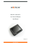
1.2.2.
Watchdog Timing Diagram
Figure 1.
6
The Single Trigger Mode is a variant of the Single Event
Mode. It also switches off after generating the event of
the last defined stage. Additionally, it switches off when it
gets triggered the first time.
Single-stage / Single-event mode
Watchdog Operation User Manual
Figure 2.
1.2.3.
Multi-stage / Single-event mode
Watchdog Events
The following is a description of possible Watchdog Events:
Rev 0.2 – Preliminary
NMI / IRQ
This Watchdog Event generates an interrupt. Depending
on the system implementation this may be a nonmaskable interrupt (NMI) or a normal interrupt request
(IRQ).
ACPI
This Watchdog Event generates a system management
interrupt. Depending on the system management
implementation (ACPI/APM) this may be an SCI or an
SMI. See the Notes and Cautions for more information
about the ACPI Event.
Reset
This Watchdog Event generates a reset signal.
Depending on the system implementation this may reset
the whole system, part of it, or just the CPU. In any case
after generating the reset signal the Runtime Watchdog
gets switched off and no further Watchdog stages will be
processed.
Power Button
This Watchdog Event generates a power button signal.
Depending on the system implementation this can invoke
a system shutdown, switch off the system or power up
the system.
Watchdog Operation User Manual
7
1.3.
POST Watchdog
The POST Watchdog is available during the system initialization process and is used to
recover from a malfunction of system expansions like add-in hardware or peripheral
devices. If enabled the POST Watchdog is started immediately after system power up
and automatically switched off when the POST is finished and the system is ready to load
the operating system. If the system does not finish the POST within the time period
defined by the POST Watchdog timeout, then the Watchdog generates a reset signal to
reboot the system. The granularity of the timeout value is one millisecond and the
watchdog timer may have a maximum deviation of 2%.
1.4.
Watchdog Configuration, Initialization, and Lifetime
1.4.1.
Watchdog Configuration via the CMOS Setup Utility
The setup program for the BIOS provides a CMOS setup screen that is used to configure
the Watchdog. Any changes done in the CMOS setup screen will take effect as soon as
the new values have been saved to CMOS RAM and the system is restarted.
1.4.2.
Watchdog Configuration via the CGOS API
The CGOS API is used to configure and initialize the Runtime Watchdog. Changing the
parameters via the CGOS API will take effect immediately. Please keep in mind that any
Runtime Watchdog configuration done via the CGOS API will be overwritten by the
Watchdog parameters that have been set using the BIOS setup program when the system
reboots.
1.4.3.
Initialization and Lifetime
If the POST Watchdog is enabled, then it is initialized and started every time the system
powers up or reboots. It stays active until the system reaches the end of POST. The
POST Watchdog is switched off automatically before the system starts loading the
operating system. Additionally, the POST watchdog is switched off automatically when
invoking the CMOS setup utility or when entering a BIOS boot menu.
If the Runtime Watchdog is enabled via the CMOS setup utility, then it is initialized and
started automatically at the end of POST. Additionally, it can be initialized and started at
any time during runtime via the CGOS API. Except for when in the Single Trigger Mode,
the Runtime Watchdog stays active as long as it gets triggered and the system continues
to run. The Watchdog can be switched off at any time during runtime via the CGOS API.
The Watchdog switches off automatically when being triggered in single trigger mode or
after generating a RESET EVENT.
8
Watchdog Operation User Manual
1.5.
Watchdog Triggering
Triggering the Watchdog within the Watchdog Timeout interval prevents the Watchdog
from generating an event. When there are several Watchdog stages defined, then
triggering the Watchdog also forces the Watchdog back to the first stage. There are
different methods of triggering the Watchdog. Below you will find a description of each
trigger method.
1.5.1.
Watchdog Triggering via the CGOS API
The usual method of triggering the watchdog is through the use of the CGOS API.
1.5.2.
External Trigger Method
This option is not support in the 19-inch Panel PC.
1.6.
Notes and cautions
The following notes and cautions should be observed.
1.
In ACPI mode it is not possible for a Watchdog ACPI Event handler to directly
restart or shutdown the OS. For this reason the BIOS will do one of the following:
For Shutdown:
An over temperature notification is executed. This causes
the OS to shut down in an orderly fashion.
For Restart:
An ACPI fatal error is reported to the OS.
It depends on your particular OS as to how this reported fatal error will be handled
when the Restart function is selected. If you are using Windows XP/2000 there is
a setting that can be enabled to ensure that the OS will perform a restart when a
fatal error is detected. After a very brief blue-screen the system will restart.
You can enable this setting buy going to the System Properties dialog box and
choosing the Advanced tab. Once there, choose the Settings button for the
Startup and Recovery section. This will open the Startup and Recovery dialog
box. In this dialog box under System failure there are three check boxes that
define what Windows will do when a fatal error has been detected. In order to
ensure that the system restarts after a Watchdog ACPI Event that is set to
Restart, you must make sure that the check box for the selection Automatically
restart has been checked. If this option is not selected then Windows will remain
at a blue-screen after a Watchdog ACPI Event that has been configured for
Restart has been generated. Below is a Windows screen-shot showing the
proper configuration.
Rev 0.2 – Preliminary
Watchdog Operation User Manual
9
10
2.
By using several Watchdog stages it is possible to escalate the Watchdog actions.
For example the Watchdog could generate an interrupt as a first event giving
some interrupt handler of the application the chance to recover from an error
condition. If this handler also fails to trigger the Watchdog, then the Watchdog
may generate a reset signal to restart the system.
3.
Be careful when selecting a POST Watchdog timeout value. It should be taken
into account that the power up time of peripheral devices may vary or option
ROMs, such as LAN boot ROMs, may elongate the POST process. Choosing a
POST Watchdog timeout value that is too short may be counterproductive.
Instead of ensuring that only a recovery from a true malfunction is implemented,
the system may reset periodically without a valid reason as a result of an incorrect
Watchdog Timeout value.
4.
It doesn't make any sense to select Watchdog Event RESET together with
Repeated Event Mode because the Watchdog switches off immediately after
generating the first reset signal due to the fact that a repeated reset signal is not
supported.
5.
Under normal circumstances it is not necessary to trigger the POST Watchdog.
However it is possible. This may be helpful when writing option ROMs, which
need to delay the POST in special situations. The CGOS API is not available in
that case, therefore the fast or external trigger methods can only be used.
6.
It's possible that two Watchdog stages with Power Button Events could be used to
configure defined system on/off times.
7.
The Single Trigger Event may be useful for application software, which cannot
use the CGOS API but still want to ensure that the operating system boots
completely and starts the application code. In that case the CMOS setup utility
Watchdog Operation User Manual
must be used to configure the Runtime Watchdog in Single Trigger Mode with one
stage and event RESET. Together with a POST watchdog this guarantees that
the system is restarted until it makes it to the application code. The only thing that
the application code has to do then is to switch off the watchdog via the fast or
external trigger method.
1.7.
BIOS configuration
The BIOS needs to be configured to enable the Watchdog. The section discusses this.
1.7.1.
ACPI Configuration submenu
In the ACPI Configuration Submenu, need to select the event that is initiated by the
watchdog ACPI event: Shutdown or Restart. When the watchdog times out, a critical but
orderly OS shutdown or restart can be performed.
1.7.2.
Watchdog Configuration Submenu
Feature
POST Watchdog
Options
Disabled
30sec
1min
2min
5min
10min
Description
Select the timeout value for the POST
watchdog.
The watchdog is only active during the poweron-self-test of the system and provides a facility
to prevent errors during boot up by performing a
reset.
30min
Stop Watchdog For
User Interaction
No
Runtime Watchdog
Disabled
Yes
One time trigger
Single Event
Repeated Event
Select whether the POST watchdog should be
stopped during the popup boot selection menu
or while waiting for setup password insertion.
Selects the operating mode of the runtime
watchdog. This watchdog will be initialised just
before the operating system starts booting.
One time trigger: the watchdog will be disabled
after the first trigger.
Single event: every stage will be executed only
once, then the watchdog will be disabled.
Repeated event: the last stage will be executed
repeatedly until a reset occurs.
Delay
Disabled
30sec
1min
Select the delay before the runtime watchdog
becomes active. This ensures that an operating
system has enough time to load.
2min
5min
10min
30min
Event 1
NMI
ACPI Event
Reset
Rev 0.2 – Preliminary
Selects the type of event that will be generated
when timeout 1 is reached. For more
information about ACPI Event see section
Error! Reference source not found., Error!
Watchdog Operation User Manual
11
Event 2
Power Button
Reference source not found..
Disabled
Selects the type of event that will be generated
when timeout 2 is reached.
NMI
ACPI Event
Reset
Power Button
Event 3
Disabled
NMI
Selects the type of event that will be generated
when timeout 3 is reached.
ACPI Event
Reset
Power Button
Timeout1
0.5sec
1sec
Selects the timeout value for the first stage
watchdog event.
2sec
5sec
10sec
30sec
1min
2min
12
Timeout 2
as above
Selects the timeout value for the second stage
watchdog event.
Timeout 3
as above
Selects the timeout value for the third stage
watchdog event.
Watchdog Operation User Manual
2.
CGOS API
This chapter describes version 1.03 of the CGOA API.
The CGOS API is an application program interface that allows access to certain hardware
features on the processor module. The API works under any version of Win32. Driver
support is provided for:
2.1.
•
Microsoft Windows Vista 32
•
Microsoft Windows XP
•
Microsoft Windows XP embedded
•
Microsoft Windows 2000
•
Microsoft Windows NT
•
Microsoft Windows CE 5.0
•
Microsoft Windows CE 6.0
•
Linux (Kernel Version 2.4.x and 2.6.x)
•
QNX 6.x
•
Windriver VxWorks
•
On Time RTOS-32
Installing the CGOS API
Running the sample application CGOSDUMP.EXE will dynamically install the drivers. It is
also possible to perform a dynamic installation in your own application as well. When
using Windows NT/2000/XP it is necessary to have “Administrative Rights” in order to
install the drivers, for example when running CGOSDUMP.EXE for the first time.
The CgosLibInstall function within the CGOS API, allows you to execute the necessary
steps to setup the required drivers in an operating system independent manner. The
required files must be present in the operating system dependent directory before calling
CgosLibInstall.
The following sections lists the driver files and installation functions for those who do not
want to use the CGOS install functionality. The cgos.h header file is the same for all
operating system variants.
CGOS.DLL is binary compatible between Windows 9x and NT/2000/XP/Vista, a different
version with the same name is made available for Windows CE. On some occasions it's
necessary for Motium to provide updated CGOS library files or drivers for individual
operating systems and/or product variants. When this occurs, these individual updates
may not be immediately incorporated into the CGOS API package so it's important that
you also check for individual updates when checking for new revisions of the CGOS API
package.
Rev 0.2 – Preliminary
Watchdog Operation User Manual
13
2.1.1.
Microsoft Windows NT/2000/XP/XP embedded/Vista
Copy all files from the Cgos\WIN\BIN folder to folder Windows\System32. Running
CgosDump, as long as you have “Administrative Rights”, will automatically install the
driver. This can also be accomplished by calling the function CgosLibInstall from any
CGOS application. Do not remove the files afterwards because the driver must reside in
the directory where it was initially installed.
During installation, some keys are written to the registry to specify the location of the
driver and the library. Once installed, moving the driver and/or the library to a new
location will result in an inaccessible CGOS interface. Moreover, it's assumed that the
driver (cgos.sys) and library (cgos.dll) resides in the same directory. However, if required
the registry values can easily be removed by calling CgosLibInstall(0).
2.2.
Additional Programs
2.2.1.
CGOSDUMP
The CGOSDUMP.EXE tool prints out a lot of information about the CPU module and the
CGOS interface itself, such as the BIOS version,serial number of the module, the CGOS
driver and library version, the running time meter, available I2C buses and storage areas
plus more.
CGOSDUMP.EXE is a sample program and was not designed to serve any applicable
purpose. The source code has been provided for a better understanding of how this
sample program works.
The CGOSDUMP.EXE is a sample program that has been created strictly for the use of
software developers and should never be distributed to end users in it's current form.
2.2.2.
CGOSMON
The CGOSMON.EXE tool provides information about the different voltage and
temperature sensors on the CPU module.
CGOSMON.EXE is a sample program and was not designed to serve any applicable
purpose. The source code has been provided for a better understanding of how this
sample program works.
The CGOSMON.EXE is a sample program that has been created strictly for the use of
software developers and should never be distributed to end users in it's current form.
2.2.3.
CGOSUNINST
When executing any CGOS application without proper installation of the CGOS API in a
Windows environment, the system will dynamically install the drivers. In some cases this
is not desired because the location of the driver files will be fixed by a registry entry. The
cgosuninst tool can be used to remove all the CGOS related entries from the Windows
registry. It's especially helpful when the location of the CGOS API files should be
changed.
The cgosuninst tool only removes the registry entries, files are not deleted or removed.
14
Watchdog Operation User Manual
2.3.
Programming
All the API functions are exported from the CGOS.DLL/cgos.so dynamic link library and
UNICODE is supported. CGOS.DLL is binary compatible between Windows 9x and
NT/2000/XP but a different version with the same name is made available for Windows
CE.
In the INC and LIB directories you will find a header file cgos.h and import library
CGOS.LIB for C/C++. The cgos.h header file is the same for all Windows operating
system variants.
Within the files of CGOSDUMP you will find a sample project, which demonstrates CGOS
functionality under Microsoft Visual C++. Most of following source code examples are
taken from CGOSDUMP.
2.3.1.
Installing the DLL
In order to use another API it is necessary to initialize and install the DLL by using the
CgosLibInitialize function. Additionally, it is also necessary to use the function
CgosLibUninitialize before the application terminates. This guarantees that a proper
resource cleanup has taken place before the actual termination of the application.
Code example for installing/removing the library:
if (!CgosLibInitialize()) {
if (!CgosLibInstall(1)) {
//error: the driver could not be installed. Check your rights.
exit(-1);
}
// the driver has been installed
if (!CgosLibInitialize()) {
//error: the driver still could not be opened, a reboot might be
required
exit(-1);
}
}
// CgosLibInitialize successful
// open board, access watchdog & VGA functions, etc.
...
// close board
...
// remove DLL
CgosLibUninitialize();
There are some other function calls which belong to the library management:
•
CgosLibGetVersion
determines the version of the library
•
CgosLibGetDrvVersion
determines the version of the low level
cgos driver
•
CgosLibIsAvailable
determines if the library is already installed
•
CgosLibGetLastError
returns the last interface error
•
CgosLibSetLastErrorAddress
fills a variable with the last interface error
Rev 0.2 – Preliminary
Watchdog Operation User Manual
15
2.3.2.
Obtaining access to the processor module
Board Name
In the CGOS concept, a system consist of one or more CGOS compliant boards. A board
is a physical hardware component. Each board in the system is identified by a unique
board name with a maximum size of CGOS_BOARD_MAX_SIZE_ID_STRING characters.
Board Classes
The class of the board describes the functionality the board offers. Currently, there are
the classes CPU, VGA, and IO. In most cases, a physical board offers more functionality
than that of just one single class. For instance a 945 processor board offers CPU and
VGA functionality. In the CGOS concept, therefore, each board has exactly one primary
class and may have several secondary classes. In the case of the 945, the primary class
is of type CGOS_BOARD_CLASS_CPU and the secondary class of type
CGOS_BOARD_CLASS_VGA. The function CgosBoardCount might be used to
determine the number of boards either for a given class or the entire system.
Once the library is initialized, the API functions CgosBoardOpen or
CgosBoardOpenByName are used to obtain a valid board handle. The board handle is
the tight relation between the CGOS driver and the application until it is closed by
CgosBoardClose.
Code example for opening/closing a CGOS board:
// board handle
HCGOS hCgos=0;
// open the board
if (!CgosBoardOpen(0,0,0,&hCgos)) {
//error: could not open a board
...
}
// put in your code here (e.g. setup & trigger the watchdog, etc.)
...
// close
if (hCgos) CgosBoardClose(hCgos);
2.3.3.
Generic Board Functions
Numerous CgosBoard* functions are designed to allow you to retrieve general board class
independent information about the board.
CgosBoardGetNamedetermines the version the board name for a given handle.
The CgosBoardGetInfo function call is used to get the information about the current
configuration and state of the board. It takes a pointer to an instance of structure
CGOSBOARDINFO, which is defined as follows:
CGOSBOARDINFO
unsigned long dwSize
size of the structure itself, must be initialized with sizeof(CGOSBOARDINFO)
16
Watchdog Operation User Manual
unsigned long dwFlags
reserved. Always set to 0.
char szReserved[CGOS_BOARD_MAX_SIZE_ID_STRING]
reserved. Always set to 0.
char szBoard[CGOS_BOARD_MAX_SIZE_ID_STRING]
the name of the board, extracted from the BIOS id
char szBoardSub[CGOS_BOARD_MAX_SIZE_ID_STRING]
the sub name of the board, extracted from the manufacturing data
char szManufacturer[CGOS_BOARD_MAX_SIZE_ID_STRING]
the name of the processor module manufacturer
CGOSTIME stManufacturingDate
the date of manufacturing
CGOSTIME stLastRepairDate
the date of last repair
char szSerialNumber[CGOS_BOARD_MAX_SIZE_SERIAL_STRING]
the serial number of the board, e.g. 000000050000
unsigned short wProductRevision
the product revision in ASCII notation, major revision in high-byte, minor
revision in low-byte, e.g. 0x4130 for revision A.0
unsigned short wSystemBiosRevision
the revision of the system BIOS, major revision in high-byte, minor revision in
low-byte, e.g. 0x0110 for revision 110
unsigned short wBiosInterfaceRevision
the revision of CGOS API BIOS interface, major revision in high-byte, minor
revision in low-byte, e.g. 0x0100 for revision 100
unsigned short wBiosInterfaceBuildRevision
the build counter of CGOS API BIOS interface, e.g. 0x001 for build 001
unsigned long dwClasses this entry represents an or-ed value of all the
supported board classes see also section "Board classes" for more
information about board classes
unsigned long dwPrimaryClass
this entry represents the primary board class, e.g.
CGOS_BOARD_CLASS_CPU
unsigned long dwRepairCounter
the repair counter
char szPartNumber[CGOS_BOARD_MAX_SIZE_PART_STRING]
the part number, e.g. TBC in the case of 945
char szEAN[CGOS_BOARD_MAX_SIZE_EAN_STRING]
the EAN code of the board
Rev 0.2 – Preliminary
Watchdog Operation User Manual
17
unsigned long dwManufacturer
the sub manufacturer of the board
2.3.4.
CgosBoardGetBootCounter
delivers the boot counter value
CgosBoardGetRunningTimeMeter
hours
delivers the running time of the board measured in
Watchdog
Refer to the chapter earlier in this document that describes the watchdog features, to
become more familiar with the basic Watchdog features, its implementations and the
differences between the operation modes on different products.
The CGOS Library API provides the following functions, which are used to control the
behaviour or to get information about the state of the Watchdog:
CgosWDogCount
CgosWDogIsAvailable
CgosWDogTrigger
CgosWDogGetConfigStruct
CgosWDogSetConfigStruct
CgosWDogSetConfig
CgosWDogDisable
CgosWDogGetInfo
2.3.4.1.
Mode
The mode defines the major behavior of the watchdog:
CGOS_WDOG_MODE_REBOOT_PC the watchdog just restarts the board
CGOS_WDOG_MODE_STAGED
2.3.4.2.
the watchdog operates in staged mode
(preferred)
Operation Modes
In staged mode, the Watchdog might offer one or more various operation modes:
CGOS_WDOG_OPMODE_DISABLED
CGOS_WDOG_OPMODE_ONETIME_TRIG
CGOS_WDOG_OPMODE_SINGLE_EVENT
CGOS_WDOG_OPMODE_EVENT_REPEAT
The supported modes can be determined through the CGOS Library API function call
CgosWDogGetInfo. The returned value CGOSWDINFO:dwOpModes represents a bit
mask of all supported modes. To check if the “repeated event mode” is supported by the
board controller watchdog, the following example can be used:
18
Watchdog Operation User Manual
CGOSWDINFO
dwi;
if (CgosWDogGetInfo(hCgos, CGOS_WDOG_TYPE_BC, &dwi))
{
if (dwi.dwOpModes & (1<<CGOS_WDOG_OPMODE_EVENT_REPEAT))
{
/* watchdog supports repeated event mode */
}
}
2.3.4.3.
Events
An event is implemented by the onboard hardware during the situation when a
Watchdog timeout occurs. Following events are defined:
CGOS_WDOG_EVENT_INT
defines a NMI or IRQ event
Depending on the hardware implementation, this event releases a NMI (non maskable
interrupt) or an IRQ (normal hardware interrupt). It's up to the user to install an appropriate
IRQ handler which is able to handle this type of event.
CGOS_WDOG_EVENT_SCI
defines a SMI or a SCI event
Depending on the hardware implementation, this event releases a SMI (system
management interrupt) or a SCI (ACPI interrupt). It's up to the user to install an
appropriate software handler which is able to handle this type of event.
CGOS_WDOG_EVENT_RST
defines a system reset event
This event issues a system reset. Depending on the hardware implementation, this reset
will be applied to the complete system or only to parts of the system.
CGOS_WDOG_EVENT_BTN
defines a power button event
This event activates the power button signal. It can be used to switch off and even to
switch on the board again in the case of a multistage Watchdog implementation.
2.3.4.4.
Stages
Depending on the implementation the Watchdog might offer multiple stages for executing
events. Each stage has it's own timeout value and event definition. If a stage times out,
the configured event for this stage will be executed and the next stage will be entered.
This offers the ability to implement a more refined error handling.
It is possible to define IRQ as first stage event and power button as second stage event: If
the timeout for the first stage occurs, an IRQ is generated and stage 2 becomes active. At
the same time the appropriate IRQ handler will be activated and might solve the problem
(e.g. by restarting a crashed application and triggering the Watchdog). If the triggering of
the Watchdog doesn't occur and as well the second stage times out then the system will
be shut down.
Rev 0.2 – Preliminary
Watchdog Operation User Manual
19
2.3.4.5.
Watchdog Types
Following watchdog types are currently defined:
2.3.4.6.
CGOS_WDOG_TYPE_UNKNOWN
used when the type is not known
CGOS_WDOG_TYPE_BC
the watchdog is implemented via the onboard
controller
CGOS_WDOG_TYPE_CHIPSET
the watchdog functionality is available just
through the board's chipset
Information Structure
The CgosWDogGetInfo function call is used to get information about the current
configuration and state of the Watchdog. It takes a pointer to an instance of structure
CGOSWDINFO, which is defined as follows:
CGOSWDINFO
unsigned long dwSize
size of the structure itself, must be initialized with sizeof(CGOSWDINFO)
unsigned long dwFlags
reserved. Always set to 0.
unsigned long dwMinTimeout
this value depends on the hardware implementation of the Watchdog and
specifies the minimum value for the Watchdog trigger timeout.
unsigned long dwMaxTimeout
this value depends on the hardware implementation of the Watchdog and
specifies the maximum value for the Watchdog trigger timeout.
unsigned long dwMinDelay
this value depends on the hardware implementation of the Watchdog and
specifies the minimum value for the Watchdog enable delay.
unsigned long dwMaxDelay
this value depends on the hardware implementation of the Watchdog and
specifies the maximum value for the Watchdog enable delay.
unsigned long dwOpModes
the mask of the supported operation modes, see section 2.3.4.2 Operation
Modes
unsigned long dwMaxStageCount
the amount of supported Watchdog stages, see section 2.3.4.4 Stages
unsigned long dwEvents
the mask of the supported Watchdog events, see section 2.3.4.3 Events
unsigned long dwType
see section 2.3.4.5 Watchdog Types
20
Watchdog Operation User Manual
2.3.4.7.
Configuration
The CgosWDogSetConfigStruct and CgosWDogGetConfigStruct function calls are used to
set and to determine the Watchdog configuration. Both of them take a pointer to an
instance of structure CGOSWDCONFIG which is defined as follows:
CGOSWDCONFIG
unsigned long dwSize
size of the structure itself, must be initialized with sizeof(CGOSWDCONFIG)
unsigned long dwTimeout
it specifies the value for the Watchdog timeout. It must be in the range
CGOSWDINFO:dwMinTimeout and CGOSWDINFO:dwMaxTimeout. In case
of multiple stages, this value is not used because the configuration occurs
through the appropriate stage structure.
unsigned long dwDelay
this value specifies the value for the Watchdog enable delay, see also figure 1
or figure 2 from Watchdog Timing Chart, earlier in this manual.
unsigned long dwMode
the current mode, see section 2.3.4.1 Mode
unsigned long dwOpMode
the mask of the supported operation modes, see section 2.3.4.2 Operation
Modes this value is only used in multistage mode
unsigned long dwStageCount
the number of available Watchdog stages, see section 2.3.4.4 Stages this
value is only used in multistage mode
CGOSWDSTAGE stStages[CGOS_WDOG_EVENT_MAX_STAGES]
this array holds the state definition of each defined stage these values are
only used in multistage mode
The CgosWDogSetConfig and the config structure contain time values with a millisecond
resolution. timeout is the basic time during which a CgosWDogTrigger function must be
called. delay adds an initial time period for the first trigger call.
In case of a multistage Watchdog implementation the array stStages of type
CGOSWDSTAGE contains the stage structures which incorporates the timeout and event
value for each stage. Refer also to figure 2 in the Watchdog Timing Chart section and the
definition below:
Rev 0.2 – Preliminary
Watchdog Operation User Manual
21
CGOSWDSTAGE
unsigned long dwTimeout
it specifies the time value for the affected stage. The value must be in the
range CGOSWDINFO:dwMinTimeout and CGOSWDINFO:dwMaxTimeout
unsigned long dwEvent
it contains the event definition for the affected stage, see section 4.7.3 Events
If the mode is set to staged then up to three stages can be defined. The
stages are run in the order they are specified after each timeout value has
expired without triggering the Watchdog.
The CgosWDogSetConfig function call is provided for convenience. It offers a fast and
easy way for setting up a single staged Watchdog without the necessity to handle a
complex configuration structure. However, it's recommended to use
CgosWDogSetConfigStruct to benefit from the features of a multistage Watchdog
implementation.
2.3.4.8.
Triggering
After configuring the Watchdog by CgosWDogSetConfigStruct the application must
continuously call CgosWDogTrigger that triggers the Watchdog.
2.3.4.9.
Disabling the Watchdog
An enabled Watchdog can be disabled by calling CgosWDogDisable.
22
Watchdog Operation User Manual
2.4.
CGOS Library API Programmer's Reference
The CGOS Library API provides access to specific board information and features.
All functions provide a Cgos*Count() function to retrieve the number of available units. All
other functions within that group require a dwUnit parameter. In all cases this can simply
be the zero based unit number.
Some functions and structures contain version numbers. All 16 bit version numbers
contain the major number in the high byte and the minor in the low byte in BCD. BIOS
and board controller version numbers should simply be treated as 3 BCD digits as only
that combination together with the board name yields useful information.
All 32 bit version numbers contain the 16 bit version number in the high word and a build
or subversion number in the low word.
For function call details and parameters also refer to the cgos.h header file.
2.4.1.1.
Return Values
Unless they return a count or version number, all Cgos* functions return 1 for success and
0 for failure. Other return values are stored in pointers passed to the function.
2.4.1.2.
Board Classes
In a system with several CGOS compliant boards, the board class is used to distinguish
between the hardware types of the installed boards. Currently, board classes are defined
for CPU, VGA and IO boards, respectively:
CGOS_BOARD_CLASS_CPU
CGOS_BOARD_CLASS_VGA
CGOS_BOARD_CLASS_IO
2.4.1.3.
Information Structures
The API defines several information structures in cgos.h They are used to store the
returned values during Cgos*GetInfo calls. Before using these structures, the dwSize
entry of each info structure must be initialized with the size of the structure itself
(sizeof(CGOS*INFO)). This provides independence between the application and the
library if the structure is extended in future releases of the library.
2.4.1.4.
Unit numbers
Almost all function calls take a unique unit number that is used to identify a dedicated unit.
Usually the unit number is between 0 and the return value -1 of the related Cgos*Count
function call. It can be taken as an index for devices of the same type. The following
example shows how to determine the current value of the CPU temperature sensor:
Example 1:
static CGOSTEMPERATUREINFO temperatureInfo = {0};
unsigned long dwUnit, monCount = 0, dwTemp, dwState;
temperatureInfo.dwSize = sizeof (temperatureInfo);
Rev 0.2 – Preliminary
Watchdog Operation User Manual
23
// determine number of temperature sensors
monCount = CgosTemperatureCount(hCgos);
printf("Number of temperature monitors: %d\n", monCount);
if(monCount != 0)
{
for(dwUnit = 0; dwUnit < monCount; dwUnit++)
{
if(CgosTemperatureGetInfo(hCgos, dwUnit, &temperatureInfo))
{
if (temperatureInfo.dwType == CGOS_TEMP_CPU)
{
// temperatureInfo now contains the info structure of the cpu
sensor
// dwUnit points to the cpu temperature sensor
if (CgosTemperatureGetCurrent(hCgos, dwUnit, &dwTemp, &dwState)
{
// dwTemp and dwState contain the actual values of the
cpu sensor
}
}
}
}
}
A device enumeration can always be set up as shown above. Additionally, some function
calls such as all of the CgosStorageArea* and CgosI2C* function calls can take a type
number as dwUnit parameter.
The following examples used to determine the storage area size of the user EEPROM
(type CGOS_STORAGE_AREA_EEPROM) are equivalent:
Example 2:
unsigned long dwUnit;
unsigned long dwSize;
unsigned long areaCount =
CgosStorageAreaCount(hCgos,CGOS_STORAGE_AREA_UNKNOWN);
for(dwUnit = 0; dwUnit < areaCount; dwUnit++)
{
if (CgosStorageAreaType(hCgos,dwUnit) == CGOS_STORAGE_AREA_EEPROM))
{
dwSize = CgosStorageAreaSize(hCgos,dwUnit);
}
}
Example 3:
unsigned long dwSize;
dwSize = CgosStorageAreaSize(hCgos,CGOS_STORAGE_AREA_EEPROM);
The device enumeration as shown in Example 1 is the preferred way to obtain access to
the unit information and works for all function groups. Example 3 shows a convenient way
to access the unit through its type definition but keep in mind that this method is not
available for all function groups.
24
Watchdog Operation User Manual
2.4.2.
Function Group CgosLib*
The CgosLib* functions are used to initialize and to remove the CGOS Library. The library
provides the basic layer for the application to access all the CGOS API functions. The
library must be installed before any call to CGOS API functions can be executed
successfully.
2.4.2.1.
CgosLibGetVersion
Declaration
ulong CgosLibGetVersion(void)
Remark
Returns the version of the CGOS API library. This 32 bit version number contains the
16 bit version number in the high word and a build or subversion number in the low
word.
2.4.2.2.
CgosLibInitialize
Declaration
bool CgosLibInitialize(void)
Remark
Initializes the CGOS API library.
2.4.2.3.
CgosLibUninitialize
Declaration
bool CgosLibUninitialize(void)
Remark
De-initializes the CGOS API library and removes it from memory.
2.4.2.4.
CgosLibIsAvailable
Declaration
bool CgosLibIsAvailable(void)
Remark
Checks if the CGOS API library has already been initialized by a prior call to function
CgosLibInitialize.
2.4.2.5.
CgosLibInstall
Declaration
bool CgosLibInstall(unsigned int install)
Input
install
1 – installs the low level CGOS driver
0 – removes the low level CGOS driver
Remark
Rev 0.2 – Preliminary
Watchdog Operation User Manual
25
This function can be used to install the low level CGOS driver if a prior call of
CgosLibInitialize failed. Keep in mind that you might need administrative privileges for
executing this function successfully. See also section Installing the DLL for a more
detailed description about installing the CGOS API library.
2.4.2.6.
CgosLibGetDrvVersion
Declaration
ulong CgosLibGetDrvVersion(void)
Remark
Returns the version of the low level CGOS driver.
2.4.2.7.
CgosLibGetLastError
Declaration
ulong CgosLibGetLastError(void)
Remark
Returns the last known error code of the low level CGOS driver. Notice that this
function really delivers the code of the last known CGOS driver error and not the
result of the last CGOS API function call. A succeeding CGOS API call doesn't affect
the return value of this function.
The following error codes are currently defined:
description
2.4.2.8.
error code
generic error
-1 (0xFFFF FFFF)
invalid parameter
-2 (0xFFFF FFFE)
function not found
-3 (0xFFFF FFFD)
read error
-4 (0xFFFF FFFC)
write error
-5 (0xFFFF FFFB)
timeout
-6 (0xFFFF FFFA)
CgosLibSetLastErrorAddress
Declaration
bool CgosLibSetLastErrorAddress(unsigned long *pErrNo)
Input
pErrNo
buffer where the error code will be stored
Remark
With this function it's possible to specify a local memory location in the context of the
application where the last error code will be stored. It provides a convenient way of
implementing error handling without calling the CgosLibGetLastError function after
each regular CGOS API function call. See section CgosLibGetLastError for a detailed
list of valid error codes.
26
Watchdog Operation User Manual
2.4.3.
Function Group CgosBoard*
The CgosBoard* routines are used to obtain a handle to a dedicated board and specific
board information like the number of boots or the total running time.
2.4.3.1.
CgosBoardCount
Declaration
ulong CgosBoardCount(unsigned long dwClass,unsigned long
dwFlags)
Input
dwClass
the hardware class of the board, see also 4.2 subsection Board
classes
dwFlags
either CGOS_BOARD_OPEN_FLAGS_DEFAULT or
CGOS_BOARD_OPEN_FLAGS_PRIMARYONLY
CGOS_BOARD_OPEN_FLAGS_DEFAULT
counts all boards of the given hardware class
CGOS_BOARD_OPEN_FLAGS_PRIMARYONLY
counts only boards which primary board class matches the given
hardware class
Remark
Returns the number of installed CGOS compliant boards with the specified board
class dwClass. In case of dwClass is 0, the total number of boards in the system will
be returned.
2.4.3.2.
CgosBoardOpen
Declaration
bool CgosBoardOpen(unsigned long dwClass, unsigned long dwNum,
unsigned long dwFlags, HCGOS *phCgos)
Input
dwClass
the hardware class of the board, see also 4.2 subsection Board
classes
dwNum
the subsequent number of the selected board in it's class, starting
from 0
dwFlags
either CGOS_BOARD_OPEN_FLAGS_DEFAULT or
CGOS_BOARD_OPEN_FLAGS_PRIMARYONLY
CGOS_BOARD_OPEN_FLAGS_DEFAULT
scans for all boards of the specified hardware class, regardless if it's
the primary class or the secondary class
Rev 0.2 – Preliminary
Watchdog Operation User Manual
27
CGOS_BOARD_OPEN_FLAGS_PRIMARYONLY
scans for boards which primary board class matches the specified
hardware class
phCgos
buffer where the board handle will be stored
Remark
Each CGOS compliant board in the system will be addressed by its own unique board
handle. This function is used to open such a board and to obtain a valid board handle.
If there is more then one CGOS board in the system, each board can be individually
selected by its board class dwClass and a subsequent enumeration of dwNum. On
success, the function returns the board handle in *phCgos.
CGOS_BOARD_OPEN_FLAGS_PRIMARYONLY might be used for dwFlags to select
a board of a dedicated board class. Together with an enumerated counter starting
from 0 the board can be addressed exactly. For instance, the call to open the 2nd
(cgos compliant) vga board would be:
HCGOS hcgos;
CgosBoardOpen(CGOS_BOARD_CLASS_VGA,1,CGOS_BOARD_OPEN_FLAGS_PRIMARYONLY,&hc
gos);
2.4.3.3.
CgosBoardOpenByName
Declaration
bool CgosBoardOpenByName(const char *pszName, HCGOS *phCgos)
Input
pszName
the name of the board, e.g. “X945” in case of a 945 CPU module
phCGOS
buffer where the board handle will be stored
Remark
This function behaves like CgosBoardOpen except that the board is specified by its
name. On success, the function returns the board handle in *phCgos.
2.4.3.4.
CgosBoardClose
Declaration
bool CgosBoardClose(HCGOS hCgos)
Input
hCgos
the board handle
Remark
Closes a board which was previously opened by either CgosBoardOpen or
CgosBoardOpenByName.
28
Watchdog Operation User Manual
2.4.3.5.
CgosBoardGetName
Declaration
bool CgosBoardGetName(HCGOS hCgos, const char *pszName,
unsigned long dwSize)
Input
hCgos
the board handle
pszName
buffer where the board name will be stored
dwSize
size of the buffer in bytes, should be at least
CGOS_BOARD_MAX_SIZE_ID_STRING
Remark
Determines the name of the board addressed by hCgos.
2.4.3.6.
CgosBoardGetInfo
Declaration
bool CgosBoardGetInfo(HCGOS hCgos, CGOSBOARDINFO *pBoardInfo)
Input
hCgos
the board handle
pBoardInfo
the buffer where the board information will be stored
Remark
Gets the board information of a CGOS API compliant board addressed by hCgos. See
section 4.3 Generic Board Functions for a detailed description of the
CGOSBOARDINFO structure.
2.4.3.7.
CgosBoardGetBootCounter
Declaration
bool CgosBoardGetBootcounter(HCGOS hCgos, unsigned long
*pdwCount)
Input
hCgos
the board handle
pdwCount
the variable where the boot counter value will be stored
Remark
Gets the current value of the boot counter.
Rev 0.2 – Preliminary
Watchdog Operation User Manual
29
2.4.3.8.
CgosBoardGetRunningTimeMeter
Declaration
bool CgosBoardGetRunningTimeMeter(HCGOS hCgos,
unsigned long *pdwCount)
Input
hCgos
the board handle
pdwCount
the variable where the value of the running time meter will be stored
Remark
Gets the current running time of the board measured in hours.
2.4.4.
Function Group CgosWDog*
2.4.4.1.
CgosWDogCount
Declaration
ulong CgosWDogCount(HCGOS hCgos)
Input
hCgos
the board handle
Remark
Returns the number of installed Watchdogs in the system.
2.4.4.2.
CgosWDogIsAvailable
Declaration
bool CgosWDogIsAvailable(HCGOS hCgos, unsigned longdwUnit)
Input
hCgos
the board handle
dwUnit
unit number
Remark
Determines if the Watchdog is present.
2.4.4.3.
CgosWDogTrigger
Declaration
bool CgosWDogTrigger(HCGOS hCgos, unsigned long dwUnit)
Input
hCgos
the board handle
dwUnit
unit number
Remark
Triggers the Watchdog.
30
Watchdog Operation User Manual
2.4.4.4.
CgosWDogGetConfigStruct
Declaration
bool CgosWDogGetConfigStruct(HCGOS hCgos, unsigned long dwUnit,
CGOSWDCONFIG *pConfig)
Input
hCgos
the board handle
dwUnit
unit number
pConfig
the pointer to the configuration structure
Remark
Determines the configuration of the Watchdog.
2.4.4.5.
CgosWDogSetConfigStruct
Declaration
bool CgosWDogSetConfigStruct(HCGOS hCgos, unsigned long dwUnit,
CGOSWDCONFIG *pConfig)
Input
hCgos
the board handle
dwUnit
unit number
pConfig
the pointer to the configuration structure
Remark
Sets the configuration of the Watchdog.
2.4.4.6.
CgosWDogSetConfig
Declaration
bool CgosWDogSetConfig(HCGOS hCgos, unsigned long dwUnit,
unsigned long timeout, unsigned long delay, unsigned long mode)
Input
hCgos
the board handle
dwUnit
unit number
timeout
the value in milliseconds before the Watchdog times out. An
application which is observed by the Watchdog must call
CgosWDogTrigger within the specified time.
delay
the delay before the Watchdog starts working. This is required to
prevent a reboot while the operating system or the application
initializes.
Remark
Sets the configuration of the Watchdog. While CgosWDogSetConfigStruct takes a
complete structure, CgosWDogSetConfig takes single values. Use
CgosWDogSetConfigStruct to benefit from the advantages of a staged Watchdog.
Rev 0.2 – Preliminary
Watchdog Operation User Manual
31
2.4.4.7.
CgosWDogDisable
Declaration
bool CgosWDogDisable(HCGOS hCgos, unsigned long dwUnit)
Input
hCgos
the board handle
dwUnit
unit number
Remark
Disables the Watchdog.
2.4.4.8.
CgosWDogGetInfo
Declaration
bool CgosWDogGetInfo(HCGOS hCgos, unsigned long dwUnit,
CGOSWDINFO *pInfo)
Input
hCgos
the board handle
dwUnit
unit number
pInfo
pointer to the Watchdog information structure
Remark
Gets the information structure of the Watchdog.
32
Watchdog Operation User Manual