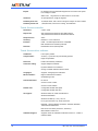
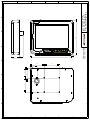
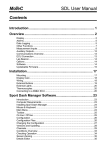
1
MLC-810 20cm (8.0”) TUFF VIEW LCD Monitor User Manual Revision 1.0 www.motium.com Revision History Rev Data 1.0 15 Feb 10 Changes Release. DRN CHK APP AW AL BD Motium is a registered trademark of Motium Pty Ltd. Microsoft Windows is a registered trademark of Microsoft Corporation. All other product names or trademarks are properties of their respective owners. Document Number: 125-19-01 Whilst every care has been taken in the preparation of this document, inaccuracies due to typographical or other errors may be present. No warranty of accuracy or reliability is given in relation to any advice or information contained in this document and no responsibility for any loss or damage whatsoever arising in any way for any representation, act or omission whether express or implied (including responsibility to any person by reason of negligence) is accepted by Motium Pty Ltd (Motium) or any officer, agent or employee of Motium. Motium reserves the right to alter the specifications of this product at any time, without prior notice. This document is copyright and all rights are reserved. This document may not, in whole or part, be copied, photocopied, reproduced, translated or reduced to any electronic medium or machine readable form without the prior consent, in writing, from Motium. Copyright © 2010 Motium Pty Ltd. 2 MLC-810 TUFF VIEW LCD Monitor Table of Content 1. Safety instructions................................................................................................ 7 1.1. 2. 3. 4. 5. 6. Introduction ........................................................................................................... 9 2.1. Features........................................................................................................ 9 2.2. Intended applications.................................................................................. 10 2.3. Ordering options ......................................................................................... 10 2.4. Specifications.............................................................................................. 10 2.5. About this manual....................................................................................... 10 Physical overview ............................................................................................... 11 3.1. Unpacking................................................................................................... 11 3.1.1. Inspection.......................................................................................... 11 3.1.2. Packaging ......................................................................................... 11 3.2. Dimensions ................................................................................................. 11 3.3. Front view ................................................................................................... 12 3.3.1. Keypad functions .............................................................................. 13 3.4. Rear view.................................................................................................... 14 Connector pin assignments............................................................................... 15 4.1. Connector type ........................................................................................... 15 4.2. Pin assignments ......................................................................................... 15 4.3. Cable information ....................................................................................... 18 Installation considerations ................................................................................ 19 5.1. For your safety............................................................................................ 19 5.2. Input voltage wiring..................................................................................... 19 5.2.1. Reverse polarity protection ............................................................... 20 5.2.2. Transient protection .......................................................................... 20 5.2.3. Input fuse considerations .................................................................. 20 5.3. Environmental Factors................................................................................ 20 5.3.1. Temperature...................................................................................... 20 5.3.2. Humidity ............................................................................................ 20 5.3.3. Altitude .............................................................................................. 20 5.3.4. Outdoors ........................................................................................... 21 5.3.5. Vibration ............................................................................................ 21 5.4. Mounting ..................................................................................................... 21 5.5. Power consumption .................................................................................... 22 5.5.1. Minimising power consumption......................................................... 22 Care and Maintenance........................................................................................ 23 6.1. User Manual Notices and warnings ................................................................................... 7 Rev 1.0 Removable protective film .......................................................................... 23 3 7. 8. 4 Getting started and OSD operation................................................................... 25 7.1. Getting started ............................................................................................ 25 7.2. Optimizing sunlight readability.................................................................... 26 7.3. Brightness control....................................................................................... 26 7.4. On Screen Display (OSD) .......................................................................... 26 7.4.1. Navigating through the OSD menus ................................................. 26 7.4.2. OSD top-level menus........................................................................ 27 7.4.3. Brightness and Contrast ................................................................... 28 7.4.4. Colour................................................................................................ 28 7.4.5. Position ............................................................................................. 29 7.4.6. Tools ................................................................................................. 29 7.4.7. Exit .................................................................................................... 30 Touch screen operation ..................................................................................... 31 8.1. Driver CD .................................................................................................... 31 8.2. Touch Screen driver ................................................................................... 31 8.3. Touch screen operation.............................................................................. 32 8.3.1. Right mouse button on the touch screen .......................................... 32 8.4. Touch screen calibration ............................................................................ 33 8.4.1. 4-point calibration.............................................................................. 33 8.4.2. 9-point calibration.............................................................................. 33 8.4.3. 25-point calibration............................................................................ 34 8.4.4. Draw test ........................................................................................... 34 8.5. On-screen keyboard ................................................................................... 34 A. Appendix A – Specifications............................................................................ 35 B. Appendix B – Dimensions................................................................................ 39 MLC-810 TUFF VIEW LCD Monitor Warranty Policy Limited Warranty Motium’s detailed Limited Warranty policy can be found at http://www.motium.com/support/. The limited warranty is void if: the product has been subjected to alteration, neglect, misuse, or abuse; if any repairs have been attempted by anyone other than Motium or its authorised agents; if the failure is caused by accident, acts of God, or other causes beyond the control of Motium. Neglect, misuse, and abuse shall include any installation, operation, or maintenance of the product other than in accordance with the User Manual. No agent, dealer, distributor, service company, or other party is authorised to change, modify, or extend the terms of this Limited Warranty in any manner whatsoever. Motium reserves the right to make changes or improvements to any product without incurring any obligation to similarly alter products previously purchased. Limitation of Liability In no event shall Motium Pty Ltd be liable for any defect in hardware, software, loss, or inadequacy of data of any kind, or for any direct, indirect, incidental, or consequential damages in connection with or arising out of the performance or use of any product furnished hereunder. Motium’s liability shall in no event exceed the purchase price of the product purchased hereunder. The foregoing limitation of liability shall be equally applicable to any service provided by Motium or its authorised agent. User Manual Rev 1.0 5 This page left blank intentionally. 6 MLC-810 TUFF VIEW LCD Monitor 1. Safety instructions To prevent damage to the product and to ensure your own personal safety, please read this safety instructions chapter before handling the product. There are no user serviceable parts inside the monitor. Only qualified, experienced, and authorised electronics service personnel should access the interior of the unit. WARNING High voltages are present inside the enclosure when power is connected to the monitor. Turn off system power and disconnect the power cable from its source before removing the rear panel. Turning the monitor off (via the Power On/Off button) does not remove power to all internal components. CAUTION Do not attempt to service the monitor yourself. Follow installation and troubleshooting instructions closely. 1.1. Notices and warnings Please pay attention to the following: 1. Read these instructions carefully and keep this user's manual for later reference. 2. When cleaning, do not use liquid or spray detergents. Use a damp cloth. 3. Dropping the monitor, or letting it fall, could cause damage, and void the warranty. 4. Make sure the voltage of the power source is correct before connecting power to the monitor. 5. Position the monitor’s Power and Signal Cable so that people cannot step or trip on it. Make sure the cable is not under strain (i.e., has some slack) when it is connected. 6. All cautions and warnings on the monitor should be noted. 7. Never pour any liquid into an opening. This could cause fire or electrical shock. 8. Never open the monitor. For safety reasons, only qualified service personnel should open the monitor. 9. If any of the following situations arise, get the unit checked by service personnel: The Monitor Power and Signal Cable is damaged. Liquid has penetrated into the monitor. The monitor has been submerged in water for longer than 15 minutes. The monitor does not work well, or you cannot get it to work according to the user’s manual. The monitor has been dropped and damaged. The monitor has obvious signs of breakage or tampering. 10. Do NOT leave the monitor in an environment where the storage temperature is below -20°C (-4°F) or above 80°C (176°F), as damage may result. User Manual Rev 1.0 7 This page left blank intentionally. 8 MLC-810 TUFF VIEW LCD Monitor 2. Introduction Thank you for purchasing a Motium Tuff View LCD monitor. We are sure you will be pleased with your choice. Motium's MLC-810 Tuff View 8-inch LCD monitors have been designed for rugged environments such as industrial control and the transportation industry, be it in-vehicle for automotive (cars, busses, trucks), marine or aircraft. Each aspect of the design considered the unique needs of these markets. Image quality is brilliant, with very wide viewing angle and 800x600 native resolution. The monitor is truly sunlight readable (with touch-screen fitted). The monitor has real backlight control, removing any night-blindness issues. (On standard LCD monitors, when the brightness is adjusted, what actually happens is the colours are changed, but the light level leaving the monitor remains the same. The MLC-810 changes the actual backlight light level and leaves the colours the same.) Being IP-65/NEMA-4 sealed (front, back and sides) against water and dust ingress, the monitors can safely be splashed with water or even sprayed, at a distance, with high pressure water hoses. All connectors are also IP65 sealed. The MLC-810 has been designed for operation in continuous vibration environments, and to cope with shock. A 75mm VESA mount allows industry standard in-vehicle mounting hardware to be used. The touch screen interface supports both USB and RS232 (allowing operation with long cable runs). An internal speaker allows PC audio and warning tones to be easily heard. The MLC-810 operates from 9V to 34V DC and has a load-dump and transient protected power input, allowing direct connection to vehicle power. Typical operating power is less than 11 watts, extremely low for a monitor with this performance. An operating temperature range of -20°C to +65°C allows the MLC-810 to be used in a wide variety of conditions. 2.1. Features Key features of the MLC-810 are: User Manual 800x600 native resolution. High quality image with wide viewing angle. Truly sunlight readable (with touch screen). Real backlight control, to overcome night-blindness. Completely water and dust proof (IP65/NEMA4). 5-wire resistive touch screen with both USB and RS232. -20°C to +65°C operating temperature range. Designed for continuous vibration environments. Rugged, automotive grade connector. Rev 1.0 9 2.2. Wide input voltage range with transient protection. Standard 75mm VESA mount. Low power consumption. 8W max at full brightness. Intended applications The MLC-810 was designed for the following applications: 2.3. Transportation: automotive in-vehicle display for cars, buses, trucks, mining equipment. Marine. Trains. Aircraft. Industrial automation. Ordering options For the full list of ordering options, refer to Motium’s web site, or contact your local reseller or Motium sales office. Note that the Monitor Power and Signal Cable is ordered separately. This is because of the large variety of options for this cable. Refer to Motium’s web site for the cable options. 2.4. Specifications Detailed specifications are listed in Appendix A. 2.5. About this manual This manual is written for technically qualified people. It provides an overview of the product and a guide for installation and maintenance. This manual was formatted to be easily read in a PDF file, or printed 2-sided on A4 paper. 10 MLC-810 TUFF VIEW LCD Monitor 3. Physical overview This chapter provides an overview of the physical aspects of the monitor, including connector locations and dimensions. 3.1. Unpacking Inside the box you will find: The MLC-810 (8.0-inch, 20cm) monitor. To reduce environmental waste, no drivers or documentation are shipped with the product. All drivers and documentation are available from Motium’s web site (http://www.motium.com). The Monitor Power and Signal Cable is ordered separately and is supplied in its own package. This is because of the large variety of options for this cable. Refer to the product page on Motium’s web site to see the standard length cables available. 3.1.1. Inspection Remove all items from the box. If any items listed on the purchase order are missing, notify your supplier immediately. Inspect the product for any damage. If there is damage, notify your supplier immediately. 3.1.2. Packaging After opening the box, you might want to save the packing material for possible future use (such as shipping to the final installation location). Motium is not responsible for damage resulting from improper packing and transportation. If the original packaging is not available, ensure that the packaging used protects the monitor against damage. 3.2. Dimensions Dimensioned drawings of the MLC-810 are provided in Appendix B. User Manual Rev 1.0 11 3.3. Front view As seen in the drawing below, located on the front panel are: The LCD Panel. In the MLC-810, this is a 20cm (8.0-inch) LCD Panel, with a resolution of 800 x 600. Touch Screen. In front of the LCD Panel is a touch screen. In front of the touch screen is a layer of replaceable protection film. This protects the touch screen from damage such as scratching. Refer to Chapter 6, Care and Maintenance, for more information. Keypad. This is described in section 3.3.1, Keypad functions. Speaker. This is for audio from the PC. Microphone. This is an option. It allows audio around the monitor to be recorded. Speaker Touch Screen Keypad Microphone (Option) Figure 1. 12 Monitor front view MLC-810 TUFF VIEW LCD Monitor 3.3.1. Keypad functions The front panel keypad provides the following functions (going from left to right in the figure below): Menu button. Pressing this brings up the OSD (On-Screen Display) menu. Once in the OSD, this button is also used to select the highlighted OSD option. The OSD is described in Chapter 7, Getting started and OSD operation. A valid video input signal must be present for the OSD menu to be displayed. Brightness up and down buttons. Pressing these buttons increases and decreases the backlight brightness. There are 64 levels of brightness. These buttons control the actual brightness of the backlight (it does not do a colour shift – which is how most LCD monitors work). The brightness setting has a direct impact on power consumption. The lower the backlight brightness, the lower the power consumption. Refer to section 5.5, Power consumption, for power consumption figures. In OSD mode, these buttons are used to navigate through the menus, and adjust values (up and down). Status Indicator LED. It indicates the following: When green, a valid video signal is being received. When amber and flashing quickly, no video input is present. When amber and flashing slowly, the PC has turned off video and placed the monitor into low power mode. Power On/Off button. Press this button to turn the monitor on and off. Note that when off, the monitor is still consuming power, but in a lower power state. To set the monitor so that it consumes no power, you need to use the On/Off Control signal in the Monitor Power and Signal Cable – refer to Chapter 4, Connector pin assignments. T U F F V IE W Figure 2. User Manual Rev 1.0 Keypad front view 13 3.4. Rear view As seen in the drawing below, located on the rear panel are: The Monitor Signal Connector. The pin assignments and connector mating models are described in Chapter 4, Connector pin assignments. The connector on the back of the monitor has male pins, while the cable end has female sockets. This is for safety, because the cable side carries power. The male pins are recessed quite far into the connector, so they cannot be accidentally damaged. The connector is polarised, and protected from misalignment, so the pins cannot be damaged during mating. The cable-end can be straight or right angle. 75mm VESA Mount. The monitor can be attached to a standard VESA bracket. We suggest using M4 screws with a 12mm thread length (maximum 14mm of thread), assuming the mounting plate on the VESA bracket is 2mm thick. Cable Clamp. This allows the Monitor Power and Signal Cable to be clamped to the rear panel using one or two P-clips. Alternatively, the cable can be secured to the mounting bracket. Note All six M4 threaded holes are blind, so there is no risk of water or dust penetrating the unit. VESA Monitor Signal Connector VESA VESA Cable Clamp Cable Clamp Figure 3. 14 VESA MLC-810 rear view MLC-810 TUFF VIEW LCD Monitor 4. Connector pin assignments This chapter lists the pin assignments for the Signal and Power Connector on the monitor’s rear panel. The connector wiring is standard on Motium Tuff View monitors, (although different models have different functionality). 4.1. Connector type The connector on the monitor is a 37-pin panel-mount connector, with 24 male pins fitted. All unused pins have a dummy plug fitted, to ensure the monitor is water and dust proof when the connector is not mated. The mating part (i.e., the female connector on the cable) is: Connector model number: AS614-35SN-090. Crimp socket number: 38943-22. (Suitable for 22 to 26 AWG wire.) Filler plug number: 600300-22. These components are available from Motium, as a kit. 4.2. Pin assignments The figures below show the front and rear views of the cable-side connector. The pin assignments are listed in the table on the following page. Figure 4. Left: Drawing looking at the front (socket-side) of the connector on the cable. Right: Drawing looking at the rear (wire-side) of the connector on the cable. User Manual Rev 1.0 15 Pin Signal Description 1 -- reserved 2 -- reserved 3 -- reserved 4 -- reserved 5 -- reserved 6 RED Red video signal. For best performance (and for long cables), this should be the center conductor a co-axial wire, with RED GND being the outer shield of the coax. If using individual wires, run in a twisted pair with RED GND. 7 GREEN Green video signal. For best performance (and for long cables), this should be the center conductor a co-axial wire, with GREEN GND being the outer shield of the coax. If using individual wires, run in a twisted pair with GREEN GND. 8 BLUE Blue video signal. For best performance (and for long cables), this should be the center conductor a co-axial wire, with BLUE GND being the outer shield of the coax. If using individual wires, run in a twisted pair with BLUE GND. 9 VGA GND 10 HSYNC This is the ground wire in the standard DB15 VGA connector. It is the return signal for the HSYNC, VSYNC, and DDC signals. Horizontal Synchronisation signal. For best performance, run in a twisted pair with VGA GND. 11 Audio GND 12 -- 13 Speaker + 14 Frame GND 15 PWR+ 16 On/Off Control Audio ground. This is the ground return signal for speaker and microphone (optional) audio. reserved Speaker audio input. The input is designed for a nominal 1V RMS audio signal. This input is buffered and amplified inside the monitor. Connect the outer shield of the cable to this pin. Monitor power, positive input. This signal controls if the monitor is on or off. This turns off all circuitry in the monitor, for absolute minimum power consumption. A positive voltage (above 3 volts) turns the monitor on. Maximum voltage on this pin is PWR+. If not required, do not connect. 16 MLC-810 TUFF VIEW LCD Monitor 17 Emergency 18 -- reserved 19 -- reserved 20 -- reserved 21 -- reserved 22 RED GND 23 GREEN GND 24 BLUE GND 25 VSYNC 26 DDC-SCL DDC clock signal. If not required, do not connect. 27 DDC-SDA DDC data signal. If not required, do not connect. 28 PWR- 29 -- reserved 30 -- reserved 31 -- reserved 32 V-Bus USB +5V. No power is taken from this signal, but the voltage must be present for the monitor to detect that it is connected to a USB port. 33 RS232 Tx RS232 Transmit Data output. This connects to the PC’s Receive Data in signal (pin 2 on the PC’s DB9 connector). 34 RS232 Rx RS232 Received Data input. This connects to the PC’s Transmit Data out signal (pin 3 on the PC’s DB9 connector). 35 USB D+ USB D+ signal. This signal must be run in a twisted pair with USB D-. 36 USB D- USB D- signal. This signal must be run in a twisted pair with USB D+. 37 Serial GND Figure 5. Some monitor models have an Emergency button on the front panel. This is the open-drain output controlled by the button. If not required, do not connect. Return for Red video signal. See pin 6 description. Return for Green video signal. See pin 7 description. Return for Blue video signal. See pin 8 description. Vertical Synchronisation signal. Monitor power return (ground). Ground pin for USB (USB GND) and serial data (pin 5 on the DB9 connector). Power/Signal connector pin assignments. Note Either the RS232 or USB signals should be connected to the PC, NOT both. User Manual Rev 1.0 17 4.3. Cable information The cable used directly impacts the resulting video performance seen on the monitor. Some important things to consider when selecting the cable are: Use 24 AWG wire, if possible. Do not try to use 28AWG wire in the crimp pins, it will not be successful. For best performance use twisted pairs in the cable. As a minimum, USB and audio must be run in a twisted pair. For very long cable runs (>5 meters), ideally audio should be in a shielded (coaxial) wire. Fit a ferrite bead around the PC end of the cable – to minimise EMI from the PC. Use a cable with an outer shield, and connect this shield to the monitor’s Frame GND pin and frame ground on the PC’s DB15 and DB9 (or USB) connectors. For best performance, the RGB signals should be run in coaxial wires. 18 If for cost reasons the cable is not going to have coaxial wires, then use twisted pairs for the video signals. The signals in the pairs should be as specified in the pin assignments table. MLC-810 TUFF VIEW LCD Monitor 5. Installation considerations This chapter discusses items to be considered as part of installing the LCD monitor. 5.1. For your safety Only use the product if it is in correct working order, for the intended purpose and while keeping safety and potential dangers in mind. 5.2. Installation, connection, and configuration of the unit should only be carried out by trained personnel. Unless otherwise expressly specified, this also applies to maintenance, testing and repair. Carefully and completely read this user manual. Always pay attention to the instructions, notes and warnings. Read the safety instructions at the start of this manual. Do not make modifications to the product (either hardware or firmware) without consulting Motium. Improper modifications can cause malfunctions or damage, and will void the warranty. Motium accepts no liability for damage resulting from unauthorised or improper modifications to the product. The product is designed to be splashed with water. This includes being sprayed with a hose. It is not designed to be submerged under water. If it is submerged under water for long periods of time, the unit should NOT be powered on until examined by a suitably qualified technician. Observe the rated voltage. The product can be damaged or destroyed by the application of an incorrect voltage. The product should NOT be connected to voltages above 40 VDC. Internal protection circuitry will prevent damage from transient voltages. Prolonged high or transient voltages applied to the unit may cause external fuses (or the internal safety fuse) to blow. Observe environmental ratings. Unsuitable ambient conditions and improper installation (mainly due to high ambient temperature and insufficient ventilation) may reduce the product’s life. Ensure compliance with the stated operating conditions (see technical data), requirements at the installation site and, if applicable, maintenance regulations. No objects or liquids should be allowed to get into the product. If they do, immediately disconnect the unit from the power supply (pull out the power plug). If you notice a burnt smell or formation of smoke from a unit, immediately disconnect it from the power supply (pull out the power plug). Input voltage wiring The gauge of the wire used to connect the monitor to the voltage source should be at least 22 AWG, and heavier (20 or 18 AWG) for long cable runs. At high input currents (i.e., low input voltages), voltage drop along the wires can be significant (halving the input voltage will double the input current – and therefore, the voltage drop across the cable). Always use the largest practical wire size, to ensure minimum voltage drop. Section 5.5, Power consumption, lists the power consumption for various input voltages. Remember, input voltage drop is the sum of current flowing in both the PWR+ and PWRwires. So wire resistance (and voltage drop) needs to be calculated for both wires. User Manual Rev 1.0 19 5.2.1. Reverse polarity protection The monitor has reverse polarity protection on the power input, so external protection is not required. 5.2.2. Transient protection The monitor has a sophisticated input transient protection circuit. It has been designed for in-vehicle applications, to protect against damage from load-dump in 12V and 24V vehicles. In non-vehicle applications this circuit provides a high level of transient protection against voltage surges, etc. 5.2.3. Input fuse considerations The monitor has an internal safety fuse fitted. The current rating of this fuse is much higher than required for normal operation. It is there as a final precaution, and is not intended to replace an in-line fuse that would normally be fitted. Some points to consider when selecting an external fuse include: Slow blow vs fast blow. Maximum input current – at the input voltage range. The higher the input voltage, the lower the input current. Input current during engine crank. Fuse current rating vs ambient temperature – if the monitor is going to be used at the extremes of the its temperature range. 5.3. Environmental Factors 5.3.1. Temperature The monitor should not be exposed to ambient temperatures above 65C, while operating at maximum brightness. Doing so might overheat the liquid crystal and clear the LCD panel – this will permanently damage the liquid crystal cells in the LCD panel, and prevent them from being able to turn on and off. 5.3.2. Humidity The monitor should not be opened up in areas with very high humidity. High-humidity can cause moisture to enter and accumulate in the unit. This moisture can cause corrosion of internal components and degrade properties such as electrical resistance and thermal conductivity. Extreme moisture build-up inside the unit can result in electrical shorts, which can cause serious damage to the system. 5.3.3. Altitude Operating the unit at high altitudes (low pressures) reduces the efficiency of the heatsink. It can also cause sealed components with internal pressure, such as electrolytic capacitors, to fail or perform at reduced efficiency. The unit is not designed to operate at very high altitudes in un-pressurised compartments. 20 MLC-810 TUFF VIEW LCD Monitor 5.3.4. Outdoors The unit is not designed to operate continuously outdoors. It needs to be located in a shelter of some form. Whilst the unit is IP65 rated (water proof), it is not designed to be installed on the deck of a ship, with water constantly flowing over it. 5.3.5. Vibration The monitor has been designed to withstand continuous low-amplitude vibration, such as that found in cars and trucks. It can also withstand high levels of shock. 5.4. Mounting The monitor is designed to be mounted via a standard 75mm VESA bracket. This allows use of a wide variety of standard mounting brackets, as well as simple and robust attachment to custom brackets. Dimensioned drawings are located in Appendix B. When fitted in the passenger compartment of a vehicle, consideration needs to be given to the local laws. Some things to consider are: Obstruction of drivers viewing area. Driver and passenger safety, in case the vehicle is involved in an accident. This includes considering obstruction of air bags. Robust mounting. Even though the monitor is light, the forces involved during an accident, or during rapid acceleration or deceleration can be significant. Interference to the driver whilst the vehicle is in operation. Don’t mount in direct sun, if possible. This is to keep the temperature inside the monitor low. Direct sunlight on the monitor will heat the inside of the monitor. Note Fitting a monitor in the passenger/driver area in a vehicle (particularly a car) normally needs to comply with various regulations, and may need to be approved by a regulatory body. Each country, and often each state, have their own regulatory requirements. Make sure you check these before installing the monitor. User Manual Rev 1.0 21 5.5. Power consumption The table below shows the typical power consumption at various input voltages and operating states. The LCD Panel at “half brightness” is a comfortable viewing level in a normal office environment. Power Consumption (W) Operating state 5.5.1. 12V in 24V in LCD backlight at full brightness. W W LCD backlight at half brightness. W W LCD backlight at minimum brightness. W W Monitor turned off, using the Power On/Off button. 0.4W 0.6W Monitor turned off, using the Power On/Off signal in the connector. 0.05W 0.1W Minimising power consumption One of the best ways to minimise power consumption is to turn-off the LCD panel and it’s backlight when the display is not needed. To do this in Windows XP (it is similar in other operating systems): From the Windows Start menu, select Control Panel. Then double-click on the Display item. Select the Screen Saver tab. 22 Press the Power button. Set Turn-off monitor to a suitable period of time, such as After 5 mins or After 10 mins. This sets the duration of time of keyboard, mouse or touch screen inactivity after which the display is turned off. In the Screen Saver tab, there is a Screen saver item. Setting this to (None) also reduces power consumption – the screen saver display still runs, even though the display is off (therefore the CPU is being used, which consumes power). MLC-810 TUFF VIEW LCD Monitor 6. Care and Maintenance The product requires little in the way of maintenance. Things to consider are: The rear panel is used to dissipate heat that might otherwise build-up inside the monitor. Keep the rear panel free of dust and dirt buildup, as this will reduce its effectiveness. If there is a large amount of dust, this should be cleaned off, using a firm-bristled brush (not a wire brush). The touch screen, and enclosure should be cleaned with a soft, dry cloth. 6.1. Do not use harsh abrasive materials as this will scratch the surface. A lint-free cloth with water or Isopropyl Alcohol can be used to clean the front of the touch screen. Products designed to clean the front of LCD monitors can also be used. Persistent dirt can be removed using a damp soft cloth (use only a mild detergent). If the unit is very dirty, it can be hosed down first. In this case, make sure the mating connector is plugged into the connector on the monitor’s rear panel (or keep water way from the connector). Removable protective film The monitor is supplied with a removable protective film fitted on top of the touch screen, to protect its surface from damage. (The touch screen’s surface can be scratched when operators have sand or metal filings on their fingers, or where there is a chance operators will use sharp objects such as screwdrivers.) The film needs to be replaced when its surface is damaged (scratched), and it becomes difficult to read the monitor. The film is placed approximately 1mm in from each edge of the plastic case. To remove the film, lift one corner, using something made of soft-plastic (so there is no risk of scratching the touch screen), and then peel the film off. To fit the replacement film: Confirm the touch screen’s surface is free of dust and fingerprints. Remove the release liner (clear colour) from the rear of the film. Starting at one corner, place the film on top of the touch screen, and slide your finger along one side, so the film is aligned with the edge of the plastic case. Move your finger along the center of the film, from one side of the monitor to the other, so that the film is in contact with the touch screen’s surface. Work from the center to the edges, making sure that no air is trapped between the film and the touch screen. Any trapped air bubbles need to be pushed to the edges, otherwise they will be a distraction. Finally, remove the protective release liner (green colour) from the front of the film. Refer to Motium’s web site, or contact your local reseller, for ordering information. Motium’s web site also includes a video showing how to replace the film. User Manual Rev 1.0 23 This page left blank intentionally. 24 MLC-810 TUFF VIEW LCD Monitor 7. Getting started and OSD operation This chapter provides an overview of connecting the monitor to a computer, and then describes the OSD. 7.1. Getting started This section assumes that the Monitor Power and Signal Cable being used has standard PC-compatible connectors on one end (as opposed to a custom connector), as shown in the photograph below. Figure 6. Photograph of a typical Monitor Power and Signal Cable, with standard PC-compatible connectors (DB15 for video, USB for touch screen and 3.5mm for audio). It also has a 4-pin 3.96mm Socket for DC power. The monitor can be used with any computer that has a standard VGA-compatible video output. To get the monitor working: Plug the Monitor Power and Signal Cable into the connector on the monitor’s rear panel. The connector is polarized, so can only be plugged in one way. Video: Plug the DB-15 connector (on one end of the Monitor Power and Signal Cable) into the PC. Touch Screen: Plug the USB (or RS232) connector into the PC. If a USB interface is being used, the USB connector should only be plugged into the PC AFTER the touch screen driver has been installed – otherwise the driver may not install correctly. Audio: Plug the 3.5mm connector into the PC’s speaker output. Power: Connect DC power to the power connector. Turn the power supply on. Press the monitor’s Power On/Off button, to turn the monitor on. Now turn the PC on. You should see the PC boot screens, etc. For best video performance, set the PC’s output video resolution to 800x600 at 60Hz. User Manual Rev 1.0 25 Note A PC’s BIOS does not support touch screen operation. The touch screen can only be used once the operating system has started and only after the touch screen drivers have been installed (described in Chapter 8, Touch screen operation). 7.2. Optimizing sunlight readability To optimise reading the screen in direct sunlight, we recommend: 7.3. Setting the Contrast Ratio in the OSD to 75%. This is the default. Setting the Brightness in the OSD to 60% (the default is 50%). This level (60%) does impact the normal light-level viewing – it washes out some of the colours. Use a high-contrast colour scheme on the PC. Brightness control The front panel keypad contains brightness Up and Down buttons. Pressing these buttons increases and decreases the backlight brightness – there are 64 levels. When one of the buttons is pressed, the backlight brightness setting is displayed on the LCD. Figure 7. Backlight brightness level on-screen display These buttons control the actual brightness of the backlight (it does not do a colour shift – which is how most LCD monitors work). The brightness setting has a direct impact on power consumption. The lower the backlight brightness, the lower the power consumption. Refer to section 5.5, Power consumption, for power consumption figures. 7.4. On Screen Display (OSD) The On Screen Display (OSD) allows you to tune the image displayed on the monitor to the PC it is connected to. 7.4.1. Navigating through the OSD menus To use the OSD: 26 Press the Menu button on the front panel keypad to bring up the OSD menu. A valid video input signal must be present for the OSD menu to be displayed. The OSD menu is divided into two sections: the main menu tabs (shown in the top half of the OSD window), and the menu options (shown in the bottom half of the OSD window). MLC-810 TUFF VIEW LCD Monitor 7.4.2. Press the brightness Up and Down buttons to move right and left along the Main OSD menus. Once the desired menu is highlighted, press the Menu button again to enter the sub-menu. Press the brightness Up and Down buttons to move right and left along the menu options. Once the desired item is highlighted, press the Menu button again to select the item. Press the brightness Up and Down buttons to adjust the setting up and down. Once the desired level is reached, press the Menu button again to exit the OSD. To exit the OSD, select the exit item, or wait a few seconds (while not pressing any buttons). OSD top-level menus Going from left to right, in the photograph below, the OSD menu tabs are: Input Selection. This allows selection between a VGA or DVI video input. The MLC-810 is fixed to VGA. Brightness and Contrast. Colour temperature. Position. Tools. Exit. This exits the OSD. Figure 8. User Manual Rev 1.0 OSD top-level menus and Video Source Selection. 27 7.4.3. Brightness and Contrast The options under the Brightness and Contrast menu are: Brightness. This is the brightness adjustment on a traditional LCD monitor. It performs a colour shift (making each pixel darker or lighter) rather than adjusting the actual backlight brightness. Contrast. This adjusts the contrast ratio of each pixel. Colour Control. This allows individual adjustment of the red, green and blue colours. Exit. Figure 9. 7.4.4. Brightness and Contrast adjustment. Colour The options under the Colour menu are: Auto-adjust colour. This automatically adjusts the colour settings for the incoming picture. sRGB display. Loads the sRGB colour profile. Colour temperature. Sets the monitor’s colour profile to one of the defaults selected (4200K, 5000K, 6500K, 7500K or 9300K). Not used. Not used. Allows colour balance to be manually adjusted. Exit. Figure 10. 28 Colour adjustment. MLC-810 TUFF VIEW LCD Monitor 7.4.5. Position The options under the Position menu are: Auto-adjust. Stretch. Clock phase. Move the image left or right on the screen. Move the image up and down on the screen. Exit. Figure 11. 7.4.6. Position adjustment. Tools The options under the Tools menu are: OSD setting. Reset all settings to factory defaults. Reset colour to factory defaults. Reset image position on screen to factory defaults. Sharpness. Not used. Exit. Figure 12. User Manual Rev 1.0 Factory reset. 29 7.4.7. Exit This exits the on-screen display. Figure 13. 30 Exit OSD. MLC-810 TUFF VIEW LCD Monitor 8. Touch screen operation In order to use the touch screen with a PC, touch screen drivers (for the operating system being used on the PC) need to be installed. This chapter provides an overview of the steps to install the touch screen drivers on a PC running Microsoft Windows XP (the process is similar for other versions of Windows). It then describes how to calibrate the touch screen, and provides an overview of using the touch screen. (Drivers are available for other operating systems, including Linux and QNX. Refer to Motium’s web site.) Note If the monitor has a USB touch screen interface, do NOT plug the USB connector into the computer until the driver installation process tells you to. Otherwise, the driver may not install correctly. Once the driver is installed, the monitor’s USB connector can remain plugged into the computer. If the touch screen is connected to the PC via the RS232 interface, the RS232 connector can be plugged into the computer at any time. 8.1. Driver CD Drivers are available from Motium’s web site. To minimise environmental waste, Motium does not ship a Driver CD with the product. Note The name of the driver file listed below is correct at the time of writing this manual. The name may change slightly in future as a result of driver updates. The updated drivers can be found on Motium’s web site. 8.2. Touch Screen driver The driver file to use for this is: Touch_Driver_5.0.0.5203.zip This same file is also used for Windows 2000 and Vista. A different file is needed for Windows 7. Extract the contents of the ZIP file to a folder. To install the driver: User Manual Double click on the setup.exe file in the Touch All_In_One_2k_XP_Vista_5.0.0.5203 folder. Press Run. This brings up the TouchKit window. Press Next. Leave the Install PS/2 interface driver box un-ticked, and press Next. Leave None selected and press Next. Rev 1.0 31 8.3. A window will pop up about plugging in the USB controller. If you are using a monitor with a USB touch screen interface, plug the USB connector into the computer now. Press OK. Leave the Support Multi-Monitor System box checked. Press Next to install the files in the default folder – there is no need to change this. Press Next to leave it as TouchKit – there is no need to change this. The drivers are now being installed. This takes approximately 15 seconds. Then a window with Search Controller On is displayed. It takes approximately 30 seconds to go through this stage. Wait for the Question window to come up. Say Yes to doing a 4-point calibration (section 8.4, Touch screen calibration, describes the 4-point calibration process). Close the TouchKit: USB Controller window. Once this is done, you do not have to restart the computer for the changes to take effect – although it is good practice to restart the computer at this point. This completes the installation of the touch screen driver. Touch screen operation Some useful things to know about the touch screen are: To the operating system, the touch screen looks like a digitizer tablet. 8.3.1. To the software, the touch screen looks like a mouse When you press a location on the touch screen (using the end of your finger or a stylus) the mouse pointer jumps to that location. If you press and hold in one spot, and then drag your finger (or the stylus), this is the same as holding down the left-mouse button and moving the mouse, i.e., a region is selected. Double-tapping on the touch screen, is the same as double clicking the left button on a mouse. A mouse and the touch screen can be used at the same time. Right mouse button on the touch screen To obtain a right-mouse button click on the touch screen, there are two options: The touch screen driver has an Auto Right Click option, which is enabled by default. Press and hold (for a couple of seconds) the location (on the touch screen) where you want to have a right-click, and a right-click event will happen. Go to the Touch Screen driver icon in the bottom right-hand corner of the screen. Right-click on the icon and select Display Button. This places a mouse icon in the bottom right-hand corner of the screen. When you want to perform a right-mouse click, touch the top right-hand corner of the mouse icon (the top right-hand corner will change colour to red), to indicate that the next touch on the screen will be a right-mouse click. This is a one-time 32 MLC-810 TUFF VIEW LCD Monitor event, so each time you want to do a right-mouse click you need to touch the top right-hand corner of the mouse icon first. 8.4. Touch screen calibration The touch screen must be calibrated before using it. The calibration process allows the touch controller to know where your finger is relative to a location on the screen. There are three levels of calibration: 4-point, 9-point and 25-point. Each level adds more precision. In most cases, 4-point calibration is sufficient. Note If the calibration does not work, then press the Clear and Calibrate button on the Tools tab, in the Touchkit Configuration Window, and repeat the process. 8.4.1. 4-point calibration To calibrate the touch screen (this is written for Windows XP, and is similar for other operating systems): In the bottom-right-hand corner of the Windows screen there is a Touchkit icon (Touchkit is the touch screen driver). Press and hold on this icon for a couple of seconds. This brings up a menu. Select 4 Points Calibration to go directly to the 4-point calibration function. Select Calibration Utility to bring up the Touchkit Configuration Window. This allows access to all the Touchkit touch screen configuration functions. This can also be accessed via the Windows Start Menu, by: Start -> All Programs -> Touchkit -> Configure Utility. The 4-point calibration function resides under the Tools tab. 8.4.2. When the calibration utility starts, it fills up the entire screen with a white background, and a circle (with cross-hair) in the bottom left hand corner. The circle with cross-hair flashes (changes colour between red and green). Press and hold at the center of this circle with cross-hair, until is stops blinking and changes colour to blue. A flashing circle with cross-hair now appears in the bottom-right-hand corner. Again press and hold until it stops blinking, and changes colour to blue. Repeat again for the top-right-hand corner and top-left-hand corner. This completes the calibration process. 9-point calibration To do a 9-point calibration: User Manual In the bottom-right-hand corner of the Windows screen there is a Touchkit icon (Touchkit is the touch screen driver). Press and hold on this icon for a couple of seconds. This brings up a menu. Select Calibration Utility to bring up the Touchkit Configuration Window. This allows access to all the Touchkit touch screen configuration functions. Rev 1.0 33 This can also be accessed via the Windows Start Menu, by: Start -> All Programs -> Touchkit -> Configure Utility. 8.4.3. The 9-point calibration function is under the Tools tab. Press the Linearization Button. The process is similar to the 4-point calibration described above, except there are nine points spread around the screen, instead of four. 25-point calibration To do a 25-point calibration, the process is the same as the 9-point calibration described above. However, before performing the calibration, go to the Tools tab, go to the Advanced tab, and under Linearization Style, select 25-point instead of 9-point. 8.4.4. Draw test Touchkit offers a Draw Test. This test is accessed via the Draw Test button, in the Tools tab of the Touchkit Configuration Window. The draw test is a screen with a series of horizontal and vertical lines. Running a finger or stylus along these lines allows you to very quickly see the calibration accuracy (i.e., the relationship between the postion touched on the touch screen and where the operating system thinks the touch occurred). 8.5. On-screen keyboard It is possible to run the PC without a keyboard. Often some keyboard entry is still required. This can be achieved by using a soft-keyboard. This is a keyboard which is displayed on the screen. (A keyboard can be plugged into a computer running an OnScreen Keyboard.) Microsoft Windows is supplied with an on-screen keyboard. It can be accessed from: Start -> All Programs -> Accessories -> Accessibility -> On Screen Keyboard. This keyboard is not customisable and is not available at login (,i.e., a user has to be logged in for this keyboard to be displayed). Several companies produce soft keyboard products that are fully customisable, that will operate before a user has logged in, and that support CTRL-ALT-DEL for logging into domain servers. Two products that we know of are listed below. Motium are NOT recommending these products (or offering support for them). If you know of others, we are happy to add them to this list): 34 http://www.virtual-keyboard.com/ http://www.my-t-soft.com/ MLC-810 TUFF VIEW LCD Monitor A. Appendix A – Specifications This chapter lists the specifications for the MLC-810 LCD monitor. Display Characteristics Viewable area: 4:3 aspect ratio. 162mm wide x 121.5mm high. 20.3cm (8.0-inch) diagonal. Native Resolution: 800 x 600. Dot pitch: 0.2055mm x 0. 2055mm. Contrast ratio: 500:1 typical. 400:1 minimum. Colours: 18-bit (262,144). Response time: Ton: 10ms typical. Toff: 15ms typical. Brightness: 700 nits, typical. (This value applies to indoor performance. The effective outdoor performance is greater than 1,000 nits. 1 nit = 1 2 Cd/m .) Viewing angle: Horizontal: Vertical: 140° typical, 120° minimum. Up: 50° typical and 40° minimum. Down: 70° typical and 60° minimum. LCD Controller Video input interface: VGA: Analog RGB, 0.7Vp-p. (DVI is available for OEM orders.) Input resolutions: 640x480, 800x600 and 1024x768. The monitor automatically scales the input signal. Input vertical frequency: 60Hz and 70Hz. 60Hz is recommended. Configuration: On-Screen Display (OSD) includes: Brightness, Contrast Ratio, H-position, V-position, Clock Phase and Colour Balance. User Interface Monitor controls: Front panel buttons are: Power On/Off, Backlight Brightness Up and Down, OSD menu. OSD menu controls: On Screen Display (OSD) menu control buttons are: Menu/Select, Left and Right. Audio Speaker: Front panel mounted speaker, with internal fixed-gain amplifier. The speaker is intended to connect to a PC, for operator feedback and warning tones. This is a good quality speaker, not a low-cost piezo. Microphone: Front panel mounted microphone, with internal pre-amplifier. (This is an OEM option, and is not fitted as standard.) The microphone is intended to connect to a PC, for audio recording or use in emergencies. Touch Screen User Manual Touch Type: 5-wire resistive. Glass thickness: 1.8mm. Operation force: <1N with a stylus of 0.8mm radius. Linearity: < 1.5% for both X-axis and Y-axis. Chattering: < 10ms. Rev 1.0 35 Impact: No damage with a 9g steel ball dropped into the centre of the panel from a height of 30cm. Static Load: 5kg load over a 10mm area for 10 seconds. Hardness: 3H pencil pressure, 1N @ 45 degrees. Durability write test: 10,000,000 times, with a force of 250g and a stylus of 0.8mm radius. Durability knock test: 1,000,000 times, with a force of 250g, 3Hz R8/HS60. Touch Screen controller Resolution: 2,048 x 2,048. Report rate: 250 points/second maximum with USB interface. 160 points/second maximum with RS232 interface. Response time: 20ms. Accuracy: Maximum +/-0.5% tolerance. Interface: USB1.1 or RS232 (EIA/TIA-232-F compatible. Both interfaces are transient protected. Data rate: RS232 data rate is 9,600 bps 8N1. Touch Screen driver software Calibration: Fast 4-point position. Compensation: Accuracy: 9-point and 25-point linearity position. Edge compensation. Draw test: Position and linearity verification. Controller setting: Support multiple controllers. Dynamic add/remove controllers. Change controller interface without reboot. Languages: Supports 10 languages for Windows. Mouse emulator: Right and left button emulation. Click/drawing mode. Sound notification: No sound. Sound on touch contact. Sound on touch release. Double click: Configurable double click speed. Configurable double click area. OS support: Windows 2000, XP, Vista and Windows 7. Windows Embedded Windows CE.NET (4.x, 5.0). CE 6.0. Linux (up to Kernel 2.6.x), 32-bit and 64-bit. MS-DOS: supports display resolutions: 640x480, 800x600, 1024x768 and 1280x1024. Mac OS 9.x and OS X (Power PC, Intel CPU). QNX Neutrino RTOS V6.3. COM Port Support: 36 Supports COM1 to COM256 for Windows and Linux. COM1 to COM8 for DOS. MLC-810 TUFF VIEW LCD Monitor Display support: Supports monitor/display rotation. Supports multiple monitors. Supports split monitor. Physical Characteristics Dimensions: 263mm Wide x 244mm High x 42mm Deep (plus 18mm for connector body; plus 54mm when connector is mated) Weight: 1.0kg. Shipping: Shipping dimensions: 260mm Wide x 210mm High x 85mm Deep. Shipping weight: 1.25kg. Ambient Temperature: Operating: -20°C to +65°C. Storage: -20°C to +80°C. Humidity: 10% to 90% RH, non-condensing. Sealed: IP65 and NEMA-4 (water and dust) for the entire unit. Certification: C-tick. Other certifications available on request. Power Power supply: Input voltage range 9V DC to 34V DC. Power Consumption: 8W maximum. Digital input: The monitor has a digital input for power on and off control. This input is different to the Power On/Off button. Using this input results in zero off-state power consumption. Transient protection: Load dump and other transients specified in ISO-7367. Specifications are subject to change without notice. User Manual Rev 1.0 37 This page left blank intentionally. 38 MLC-810 TUFF VIEW LCD Monitor B. Appendix B – Dimensions The following page (A3 size) shows a dimension drawing for the MLC-810 monitor. User Manual Rev 1.0 39 This page left blank intentionally. 40 MLC-810 TUFF VIEW LCD Monitor A A B C 70.4 52.8 D D 70.1 B 75 C 17.3 C D B 38 E F A 214.1 E All dimensions in MM. Scale: Not to scale. E TU F F V I E W 75 33.7 F 183.3 F G TUFF VIEW LCD Monitor MLC-810 20cm (8-inch) Front, Side and Rear Views G H H A B C D E F