1
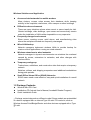
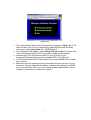
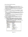
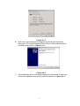
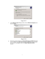
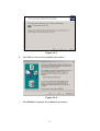
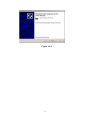
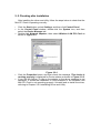
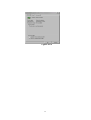
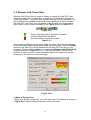
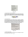
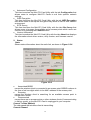
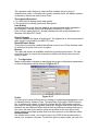
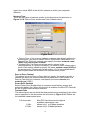
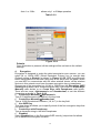
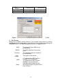
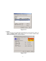
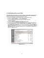
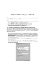
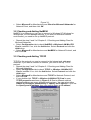
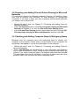
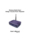
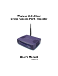
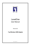
Wireless Mini-PCI Card User Manual 1 Contents Chapter 1 Introduction ..................................................................................1 1.1 Features and Benefits.........................................................................1 1.2 Package Contents ..............................................................................2 Chapter 2 Installing Drivers & Client Utility .................................................4 2-1 Installation for Windows 95/98/ME/2000/XP.......................................4 2- 2 Checking after Installation ...............................................................12 2- 3 Wireless LAN Client Utility ...............................................................14 2- 4 Uninstalling Driver and Utility...........................................................22 Chapter 3 Connecting to a Network ...........................................................23 3-1 Checking and Adding Client for Microsoft Networks .........................23 3-2 Checking and Adding NetBEUI.........................................................24 3-3 Checking and Adding TCP/IP ...........................................................24 3-4 Checking and Adding File and Printer Sharing for Microsoft Networks ................................................................................................................26 3-5 Checking and Adding Computer Name & Workgroup Name ............26 Chapter 4 Troubleshooting .........................................................................27 Appendix A Product Specifications..................................................29 Appendix B Regulatory Compliance Information .....................................31 2 Chapter 1 Introduction This product is an IEEE 802.11b Wireless Mini-PCI Card that uses a standard Type ⅢA interface which integrated with wireless LAN technology. It provides an easy and fast way to access the Internet via wireless network. This Wireless Mini-PCI Card allows the users to install on NB or PC (with an adapter) with Mini-pci interface, Wireless Access Point/Bridge/Router and other devices equipped with a Type ⅢA slot. This Wireless Mini-PCI Card is 802.11b compliant and the data rate of connection is up to 11Mbps. With an 802.11b Wireless Mini-PCI Card you can send and receive E-mail, synchronize with your desktop computer, and surf the Internet while on the move. 1.1 Features and Benefits 11Mbps data transfer rate High-speed data transmission Flexible design for embeded Can be designed or embedded for OEM system project/embedded system Fully interoperable with IEEE802.11b compliant IEEE802.11b compliant products Automatic data rate scaling at Optimized throughput, range and connectivity 11, 5.5, 2 and 1 Mbps Improved 64/128-bit WEP Significantly improved security Engine Wide coverage range up to Wireless connectivity for all your computers 800 meters in open space Advanced Power Management Extended battery life Significantly improved indoor multipath distortion Higher link quality in indoor environment High transmit power Long operating range, up to two times range of standard products 1 Wireless Solutions and Application z Access existed networks for mobile workers Allow doctors, nurses, sales access their database while keeping mobility in the hospitals, retail stores, office campus or other buildings. z Difficult-to-wire environment There are many situations where wires cannot or cannot easily be laid. Historic buildings, older buildings, open areas and across busy streets make the installation of LANs either impossible or very expensive. z Frequently changed environment Show rooms, meeting rooms, retail stores, and manufacturing sites where the workplace located are frequently rearranged. z Wired LAN backup Network managers implement wireless LANs to provide backup for mission-critical applications running on wired networks. z Wireless extensions to wired networks Network managers in dynamic environments can minimize the overhead caused by moves, extensions to networks, and other changes with wireless LANs. z Temporary workgroup Trade shows, exhibitions, and construction sites that require a temporary network. Retailers, airlines, and shipping companies need additional workstations during peak periods. z Small Office/ Home Office (SOHO) Networks SOHO users need a cost-effective, easy and quick installation of a small network. 1.2 Package Contents z z z Wireless Mini-PCI Card Installation CD (Include User’s Manual, Acrobat® Reader Program) Quick Installation Guide ☆Package content depends on different model. Some models are preinstalled in a device equipped with an internal Type IIIA mini PCI card slot, such as Wireless Access Point/Bridge/Router and other devices equipped with a Type ⅢA slot. 2 3 Chapter 2 Installing Drivers & Client Utility This chapter describes how to install the Mini-PCI Card drivers and client under Windows 95/98/ME/2000/XP. If you want to install this Wireless Mini-PCI Card in another device such as Wireless Access Point/Bridge/Router and other devices equipped with a Type ⅢA slot. Make Sure these devices can support Intersil chipset. 2-1 Installation for Windows 95/98/ME/2000/XP During the installation, Windows 95/98/ME/2000/XP may need to copy Windows system files from the Windows 95/98/ME/2000/XP installation diskette or CD-ROM.Therefore you will need a copy of the Windows installation the driver.On many syetem, instead of a CD,the necessary installation files are archived on the hard disk in C:\Windows\OPTIONS\CABS directory Installation Procedures: Before installing the new driver in your computer, you need to remove all of the Wireless LAN Mini-PCI/PCMCIA/USB Card’s driver that you had installed in your computer(Refer page 5). Please follow the installation procedures below. ◎ 1. 2. 3. Install Wireless Mini-PCI Card Driver Turn on the computer Be sure that there is no Wireless LAN Mini-PCI Card has been insterted yet Instert the Wireless LAN Installation CD into your CD-ROM drive. 4 Figure 2-1-1 1. The setup program should start automatically as shown in Figure 2-1-1. If it does not start, you can run it manually by selecting RUN from the Start menu and running Setup.htm from CD-ROM drive. 2. From Wireless LAN Installer, select Utility & Driver Install. The driver and utility of Wireless LAN Mini-PCI Card will be installed automatically. 3. Insert the Mini-PCI Card into the Mini-PCI type ⅢA slot of your computer/AP/Router/other devices equipped with a Type ⅢA slot.. 4. The Wireless LAN Mini-PCI Card will be found and installed without restart the computer. 5. Make sure that the network protocol parameters are set correctly for your computer. These include the IP address, subnet mask, gateway and DNS. If you are unfamiliar with how to set network protocol parameters, refer to Chapter 3 Connection to Network for details. 5 ◎ Remove Wireless Mini-PCI Card Driver 1. 2. Turn on your computer. Right-click on My Computer icon on the Windows desktop to choose Properties and then System Properties window will pop out. 3. Click on the tab Device Manager and then move the mouse to Network Adapters node to expend the tree list by clicking on the plus sign. 4. Remove Wireless LAN Mini-PCI Card that you have installed already. 5. Uninstall the Old Driver 6. You must remove the old existing driver before installing the new driver. 7. Click Start icon on the tool bar and select Control Panel from setting item. 8. Double click the Add/Remove Programs icon to open up Add/Remove Programs window then choose the tab Install/Uninstall, pick up the utility that you have installed for Wireless LAN Mini-PCI Card and press the button Add/Remove. 9. The dialog box will show up to confirm if you want to remove the driver and all of its components. Please click on OK button to complete the uninstallation procedure of the old driver. 10. Restart the computer and remove the Wireless LAN Mini-PCI Card. 11. Follow the Install Wireless Mini-PCI Card Driver to complete the Installation Procedure. 12. If the computer still use the old driver, please follow the step below, a. Right click the My Computer icon on the desktop and choose Properties (Windows 98/ME) or Manage (Windows 2000/XP). b. In the Device Manager window, right click the Wireless LAN Mini-PCI Card from the Network adapters’ tree list and choose the Properties as shown in Figure 2-1-2. Figure 2-1-2 6 c. Click Update Driver button from the Driver tab as shown in Figure 2-1-3. 7 d. e. Figure 2-1-3 Click next of the Welcome to Upgrade the Device Driver Wizard dialog box. The Install Hardware Device Driver dialog window will be showed up as shown in Figure 2-1-4. Figure 2-1-4 Choose Display a list of the known drivers for this device so that I can choose the specific driver and click Next as shown in Figure 2-1-5. 8 Figure 2-1-5 f. In the Network Type dialog window, choose Network adapters and then click Next . Figure 2-1-6 g. Select the network adapter for 802.11b Wireless LAN PCI Card and then click Next. The Start Device Driver Installation dialog window will show up, click Next to enter the Digital Signature Notice window. 9 Figure 2-1-7 h. Click Yes to continue the installation procedure. Figure 2-1-8 i. Click Finish to complete the installation procedure. 10 Figure 2-1-9 11 2- 2 Checking after Installation After installing the driver and utility, follow the steps below to check that the Mini-PCI Card is operating correctly. 1. 2. 3. 4. 5. Click the Start button, select Settings, and then click Control Panel. In the Control Panel window, double-click the System icon, and then select the Device Manager tab. Double-click Network adapters, then select Wireless LAN PCI Card as shown in Figure 2-2. Figure 2-2-1 Click the Properties button, and then check the message. This device is working properly is displayed for Device status as shown in Figure 2-2-2. If you find the Yellow (?) sign on the adapter or the above message is not displayed, it shows the installation is not successful or the Wireless LAN Mini-PCI Card is not operating properly. Uninstall and re-install the driver, referring to Chapter 2-6 Uninstalling Driver and Utility. 12 Figure 2-5 Figure 2-2-2 13 2- 3 Wireless LAN Client Utility Wireless LAN Client Utility is used to display or change the Mini-PCI Card information about link, configuration, encryption, and utility/driver/firmware version information. The client utility will also help you with site selection. The client utility will be installed automatically after installing the driver and utility. The Mini-PCI Card Utility icon will appear in the System Tray in the bottom right corner on your screen as shown in the Figure 2-3-1 and Table 2-3-1. Figure 2-3-1 Green indicates good or excellent link status Yellow indicates fair link status Red indicates no or poor link status Table 2-3-1 After finishing installing the driver and utility, the client utility will automatically be executed and show a small green radio icon at the right corner of Taskbar whenever the Mini-PCI Card is inserted into the Mini-PCI Card slot of your computer. Double-click the radio icon to open the Wireless LAN Client Utility window as shown in Figure 2-3-2. You can click the taps on the top of the windows to select various screen messages. Below we explain the use and meanings of the various screen messages. Figure 2-3-2 1. Menu of System Icon Right-click on the system tray icon, the icon menu will display as shown in Figure 2-3-3. Below is the introduction to this icon menu. 14 Figure 2-3-3 z Wireless Radio On/ Wireless Radio Off The first two items in the icon menu are used to turn on/off the wireless radio. When the wireless radio is turned off, a red cross is placed on the system tray icon as shown in Figure 2-3-4. When the wireless radio is turned on, the icon will vary in colors depending on the link quality as described in the Table 2-3-1. Figure 2-3-4 z Remove Status Icon This item allows you to set the System Tray Icon to appear or disappear. Once you choose this item, the system will display the dialog box to confirm if you want to remove the System Tray Icon. You can also set the System Tray Icon to disappear permanently by checking the box Remove Status Icon Permanently as shown in the Figure 2-3-5. When the computer is restarted, the System Tray Icon will come back if you have removed the System Tray Icon before but not checked the box Remove Status Icon Permanently. Figure 2-3-5 z Wireless Network Status This item launches the Mini-PCI Card Utility with the tab Status that displays the information about link status to users. 15 Advanced Configuration This item launches the Mini-PCI Card Utility with the tab Configuration that allows users to configure Mini-PCI Cards to suit their specific network settings. z WEP Encryption This item launches the Mini-PCI Card Utility with the tab WEP Encryption that allows users to set up the Encryption Key which is used in their network environment. z SITE Survey This item launches the Mini-PCI Card Utility with the tab Site Survey that allows users to browser the available active access points which users can connect to by pressing the Connect button. z Version Information This item launches the Mini-PCI Card Utility with the tab About that displays the information about driver version, utility version, and firmware version. z 2. Status State Shows status information about the radio link, as shown in Figure 2-3-6 Figure 2-3-6 Associated BSSID means the wireless client is connected to an access point. BSSID is shown in the form of six hex digits which is the MAC address of the access point. z Scanning means the wireless client is searching for an available access point in infrastructure mode. z Disconnected means there are no access points or other wireless clients (if communicating in Ad-hoc mode), or the Mini-PCI Card is unplugged in your computer. Current Tx Rate (Mbits/s) The data speed that wireless client is transmitting. Current Channel z 16 The operation radio frequency channel that wireless client is using in infrastructure mode. In infrastructure mode, wireless client will always operate in the same channel as their Access Point. Throughput (Bytes/sec) z Tx: shows the outgoing (sent) data speed. z Rx: shows the incoming (received) data speed. Link Quality In infrastructure mode, this bar displays the transmission quality between a WLAN station (Access Point) and Wireless LAN Mini-PCI Card. In Peer-to-Peer mode (Ad-Hoc), this bar displays the link quality between two Wireless LAN Mini-PCI Cards. Signal Strength This bar displays the signal strength level. The higher bar is, the more powerful radio signal is received by the Mini-PCI Card. Disable/Enable Radio This button is used like a switch that allows users to turn off the wireless radio by clicking this button and turn it on again. Rescan The radio will rescan all available channels by pressing this button. You can push this button to rescan the channels for better link quality when the link quality is poor. 3. Configuration Make configuration changes by specifying the proper configuration parameters on this configuration tab as shown in Figure 2-3-7. Figure 2-3-7 Profile You can give a name for this field to a setting of configuration parameters, such as Network Name, Network Type, Transmit Rate, Encryption (WEP Security), etc. It makes much easier for users to change WLAN configuration settings who need to switch working places frequently. Suppose that a user has to work between the two different offices where there are different network settings. In this case, this user just needs to setup two profiles for the two offices and simply selects the proper profile when the user switches to the different office. Network Name For infrastructure mode, you need to type in the SSID of the access point to which your computer connects. For Ad-Hoc (peer-to-peer) mode, you need to 17 type in the virtual SSID of the Ad-Hoc network to which your computer attaches. Network Type There are two types of network modes in this drop-down list as shown in Figure 2-3-8, Peer-to-Peer and Access Point (Infrastructure). Figure 2-3-8 Peer to Peer: If two or more stations exchange data directly without an access point, you need to select Peer-to-Peer mode. Each station in a Peer-to-Peer (Ad-Hoc) network must specify the same network name (SSID) and peer-to-peer channel. z Access Point: If at least one access point involves in the communications in a group of stations, you need to select Infrastructure mode. Each station needs to specify the same network name (SSID) as the access point. Please refer to the section 1-6 for more details about peer-to-peer mode and Access Point (infrastructure) mode. z Peer-to-Peer Channel This option is just for Peer-to-Peer (Ad-Hoc) mode. You need to specify a channel on which the communications are established. Each station in a Peer-to-Peer (Ad-Hoc) network must specify the same channel and network type (SSID). Power Save Enabled Select Power Save Enabled item to conserve more battery energy and extend the battery life. When this function is enabled, the Mini-PCI Card will be set in sleep mode between beacons. Transmit Rate The transmission rate on which the data packets are transmitted by the client can be specified in this drop-down list as shown in Figure 2-3-9. Below are the available transmission rates. Full Automatic : 11 Mb : 5.5 Mb : Mini-PCI Card chooses the highest available transmission rate allows only 1 or 2 Mbps operation allows only 5.5 Mbps operation 18 Auto 1 or 2 Mb : allows only 1 or 2 Mbps operation Table 2-3-2 Figure 2-3-9 Defaults Once this button is pressed, all the settings will be set back to the default settings. 4. Encryption Encryption is designed to make the data transmission more secure. you can select 64 or 128-bit WEP (Wired Equivalent Privacy) key to encrypt data (Default setting is Disable) as shown in Figure 2-3-10. WEP encrypts each frame transmitted from the radio using one of the Keys from this panel. When you use WEP to communicate with the other wireless clients, all the wireless devices in this network must have the same encryption key or passphrase. Choose one of the encryption key (64 bit or 128bit) from the Encryption (WEP Security) drop-down list to create encryption key. Click either on Create Keys Manually radio button or on Create Keys with Passphrase radio button. There are two ways, Alphanumeric and Hexadecimal, to set the different characters as shown in Table 2-3-3. z Create Keys ManuallyÆAlphanumeric Type 5/13 alphanumeric characters in the key field z Create Keys ManuallyÆHexadecimal Type a 10-26 hexadecimal numbers (1-9; A-F) in the key field z Use WEP Key This drop-down list allows you to specify which of the four encryption keys that you want to use. z Create Keys with Passphrase Type a character string in the field Passphrase. z Disabled Select Disabled item in the Encryption(WEP security) drop-down list allows you to disable the encryption function. 19 Data Mode 64 bit 128 bit Alphanumeric 5 13 Table 2-3-3 Hexadecimal 10 26 Figure 2-3-10 5. Site Survey Browse the available access points in your network environment by clicking the Rescan button and make a connection to one of them by pushing the Connect button in the Site Survey tab as shown in Figure 2-3-11. SSID RSSID Channel Link Quality WEP Mode The Network Type (SSID) of an access point The MAC address of an access point The operating channel number of an access point The quality of link status “Y” indicates the WEP function enabled in an access poin “N” indicates the WEP function disabled in an access point Indicates which mode does the access points use (Infrastructure or Peer to Peer) 20 Figure 2-3-11 6. About About tab shows the product/driver/utility/Mini-PCI Card firmware version as shown in Figure 2-3-12. Users have to use this version number when reporting their problems to technical support. Figure 2-3-12 21 2- 4 Uninstalling Driver and Utility If the Mini-PCI Card installation is unsuccessful for any reason, the best way to solve the problem may be to completely uninstall the Mini-PCI Card and its software and repeat the installation procedure again. 1. Insert the Wireless LAN Mini-PCI Card into the PCMCIA slot. 2. Right click My Computer--->Select Properties. 3. On the Hardware tab, choose Device Manager, and click Network .Adapter. 4. Choose Wireless LAN Mini-PCI Card and remove it. 5. After removing the Wireless LAN Mini-PCI Card, restart your computer. 6. Click the Start button, select Control Panel from Settings. Double click the Add/Remove Programs icon on the Control Panel. In the Change or Remove Programs dialog window, choose the 802.11b Wireless LAN for Windows and click Change/Remove button to uninstall this programs as shown in Figure 2-3-13. Figure 2-3-13 22 Chapter 3 Connecting to a Network This chapter describes how to prepare for connection to network after install the Mini-PCI Card drivers and utility. The following is required for all computers if you want to connect to a network. 1. Check Client for Microsoft Networks is installed. 2. Check NetBEUI -> Wireless LAN Mini-PCI Card installed. 3. Check TCP/IP -> Wireless LAN Mini-PCI Card is installed. 4. Check file and printer sharing for Microsoft Networks. 5. Check computer name and workgroup name. 3-1 Checking and Adding Client for Microsoft Networks The Client for Microsoft Networks enables you to connect to other Microsoft Windows computers and servers and use the files and printers shared on them. If you work on Microsoft network environment, you need to set up Client for Microsoft Networks. 1. 2. 3. 4. After finishing installing the driver & utility and rebooting the computer as described in Chapter 2. The computer will show a dialog box titled Enter Network Password dialog box. Enter your password if it had been set or just click Cancel. Click Start button, select Settings and then click Control Panel to open the Control Panel window. In the Control Panel window, double-click the Network icon to open the Network dialog box. Select Configuration tab to check Client for Microsoft Networks is installed as shown in Figure 3-1. If no, click the Add button. Select Client and click the Add button. 23 5. Figure 3-1 Select Microsoft for Manufacturer and Client for Microsoft Networks for Network Client, and then click OK. 3-2 Checking and Adding NetBEUI NetBEUI is a protocol you can use to connect to Windows NT, Windows for Workgroups, or LAN Manager servers. If you work on Microsoft network environment, you need to set up NetBEUI protocol. 1. 2. 3. Repeat the step 2 and 3 of Chapter 3-1 Checking and Adding Client for Microsoft Networks. Select Configuration tab to check NetBEUI -> Wireless LAN Mini-PCI Card is installed. If no, click the Add button. Select Protocol and click the Add button. Select Microsoft for Manufacturer and NetBEUI for Network Protocol, and then click OK. 3-3 Checking and Adding TCP/IP TCP/IP is the protocol you use to connect to the Internet and wide-area networks. If you want to connect to Internet, you need to set up TCP/IP protocol. 1. Repeat the step 2 and 3 of Chapter 3-1 Checking and Adding Client for Microsoft Networks. 2. Select Configuration tab to check TCP/IP -> Wireless LAN Mini-PCI Card is installed. If no, click the Add button. Select Protocol and click the Add button. 3. Select Microsoft for Manufacturer and TCP/IP for Network Protocol, and then click OK. 4. If yes, double-click TCP/IP -> Wireless LAN Mini-PCI Card to open TCP/IP properties as shown in Figure 3-2. Due to different network applications there are many different settings here. You can select either Obtain an IP address automatically or specify an IP address. If you use the Specify and IP address, then you need to enter an IP address, 24 Subnet Mask, Gateway IP address, and DNS Server IP address for connecting to Internet. Figure 3-2 25 3-4 Checking and Adding File and Printer Sharing for Microsoft Networks File and printer sharing for Microsoft networks gives you the ability to share your files or printers with Windows NT and Windows for Workgroups computers. If you want to share your files or printers with Microsoft networks, you need to set up this service. 1. 2. 3. Repeat the step 2 and 3 of Chapter 3-1 Checking and Adding Client for Microsoft Networks. Select Configuration tab to check File and printer sharing for Microsoft Networks is installed. If no, click the File and Printer Sharing button. In the File and Print Sharing window, select what you need, and click OK. File and printer sharing for Microsoft Networks, and then click OK. 3-5 Checking and Adding Computer Name & Workgroup Name Windows uses the computer name and workgroup name to identify your computer on the network. Please enter a unique name for your computer, the workgroup it will appear in, and a short description of the computer. 1. 2. Repeat the step 2 and 3 of Chapter 3-1 Checking and Adding Client for Microsoft Networks. Select Identification tab (Windows 98) or User Information tab (Windows 95) to check the computer name, workgroup and computer description are entered. If no, enter a computer name, a workgroup name and then click OK. The description field may be left blank. If you want to share data with other persons, make sure you have the same workgroup name. 26 Chapter 4 Troubleshooting This chapter describes the problems and corresponding solutions that may occur when installing a Mini-PCI Card. Symptom Solution Verify that the Mini-PCI Card is properly inserted into the Mini-PCI Card slot. Windows does not detect the Mini-PCI Card when installed. Driver fails to load Check whether the computer has a Plug and Play BIOS. Windows 95/98/ME/2000/XP might not detect the Mini-PCI Card if a previous installation of the Mini-PCI Card was cancelled before it was finished. Remove the previous driver, and redo the installation again. A resource conflict could exist. For Windows 95/98/ME/2000, use the Device Manager to resolve resource conflicts. Select System from the Control Panel, then click on the Device Manager tab. A device conflict under Windows 95/98/ME/2000/XP may be related to the Mini-PCI Card. Device conflict on a Windows system For Windows 95/98/ME/2000, use the Computer properties to identify the used I/O port addresses and IRQ values. If there is a device conflict, select alternative settings for I/O Base Address or IRQ values. If you know which device is conflicting with the Mini-PCI Card, you have the option of changing that device’s I/O address or IRQ instead of changing the Mini-PCI Card. 27 No resource conflicts were detected, but the wireless station does not attach to the network Verify that the SSID of the Mini-PCI Card matches that of the access point. Use the Network Configuration Properties Application in the Control Panel to modify the SSID. Verify that the Network Mode of the Mini-PCI Card is configured correctly. 28 Appendix A Product Specifications General Radio Data Rate 11, 5.5, 2 and 1 Mbps, Auto Fall-Back 11 Mbps –250m Range (open 5.5 Mbps –300m environment with high 2 Mbps – 600m supply current) 1 Mbps –800m Operating Voltage 3.3V Compatibility Fully interoperable with IEEE802.11b compliant products Network Information Network Architecture Support ad-hoc, peer-to-peer networks and infrastructure communications to wired Ethernet networks via Access Point Drivers Windows 95/98/ME/2000/XP Access Protocol CSMA/CA Roaming IEEE802.11b compliant Security 64/128-bit WEP data encryption Radio Frequency Band 2.4 – 2.484 GHz Radio Type Direct Sequence Spread Spectrum (DSSS) Modulation CCK (11, 5.5Mbps) DQPSK (2Mbps) DBPSK (1Mbps) Operation Channels 11 for North America, 14 for Japan, 13 for Europe, 2 for Spain, 4 for France RF Output Power 22dBm(Max. Supply Current is 750mA), 18dBm(Max. Supply Current is 500mA) Antenna connector Diversity supported by two external antenna Sensitivity @FER=0.08 11 Mbps <-86dbm 5.5 Mbps <-88dbm 2 Mbps <-90dbm 29 1 Mbps <-92dbm Power Consumption Tx Current ≦ 750 mA(used in AP/Bridge/Router) ≦ 500mA (used in NB/PC) Rx Current ≦ 240 mA Sleep Mode ≦ 200 mA Environmental Temperature Range 0 to 50 C (operating) -20 to 80 C (storage) Humidity (non-condensing) 5% to 95% typical Physical Specifications Form Factor Mini PCI Type ⅢA Interface PCI bus interface Dimensions 50.9(L) mm x 59.6(W) mm x 4.8.(H) mm 2 (L) in x 2.3(W) in x 0.2.(H) in Weight 15 g (0.53 oz.) 30 Appendix B Regulatory Compliance Information Radio Frequency Interference Requirements This device complies with Part 15 of FCC Rules and Canada RSS-210. Operation is subject to the following conditions: 1. This device may not cause harmful interference. 2. This device must accept any interference received, including interference that may cause undesired operation. 3. To comply with RF safety requirements, you must maintain a distance of 20 cm from the antenna when operating the device. 4. This transmitter must not be co-located or operating in conjunction with any other antenna or transmitter. Interference Statement This equipment has been tested and found to comply with the limits for a Class B digital device, pursuant to Part 15 of the FCC Rules, These limits are designed to provide reasonable protection against harmful interference in a residential installation. This equipment generates, uses and can radiate radio frequency energy and, if not installed and used in accordance with the instructions, may cause harmful interference to radio communications. However, there is no guarantee that interference will not occur in a particular installation. If this equipment does cause harmful interference to radio or television reception, which can be determined by turning the equipment off and on, the user is encouraged to try to correct the interference by one of the following measures: Reorient or relocate the receiving antenna. Increase the separation between the equipment and receiver. Connect the equipment into an outlet on a circuit different from that to which the receiver is connected. Consult the dealer or an experienced radio/TV technician for help. FCC Caution: To assure continued compliance, (example – use only shielded interface cables when connecting to computer or peripheral devices). Any changes or modifications not expressly approved by the party responsible for compliance could void the user’s authority to operate this equipment. 31