1
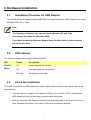
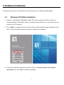
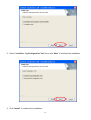
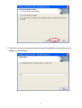
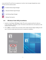
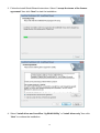
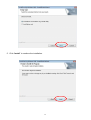
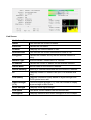
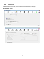
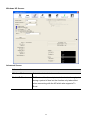
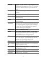
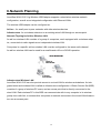
LevelOne User Manual WUA-0315 11g Wireless USB Adapter Ver. 1.0.0-1117 Safety FCC WARNING This equipment has been tested and found to comply with the limits for a Class B digital device, pursuant to Part 15 of the FCC Rules. These limits are designed to provide reasonable protection against harmful interference in a residential installation. This equipment generates, uses and can radiate radio frequency energy and, if not installed and used in accordance with the instructions, may cause harmful interference to radio communications. However, there is no guarantee that interference will not occur in a particular installation. If this equipment does cause harmful interference to radio or television reception, which can be determined by turning the equipment off and on, the user is encouraged to try to correct the interference by one of the following measures: Reorient or relocate the receiving antenna. Increase the separation between the equipment and receiver. Connect the equipment into an outlet on a circuit different from that to which the receiver is connected. Consult the dealer or an experienced radio/TV technician for help. To assure continued compliance, any changes or modifications not expressly approved by the party responsible for compliance could void the user's authority to operate this equipment. (Example - use only shielded interface cables when connecting to computer or peripheral devices). FCC Radiation Exposure Statement This equipment complies with FCC RF radiation exposure limits set forth for an uncontrolled environment. This equipment should be installed and operated with a minimum distance of 20 centimeters between the radiator and your body. This device complies with Part 15 of the FCC Rules. Operation is subject to the following two conditions: (1) This device may not cause harmful interference, and (2) This device must accept any interference received, including interference that may cause undesired operation. This transmitter must not be co-located or operating in conjunction with any other antenna or transmitter. CE Marking Warning Digital Data Communications, declares that this product (Model-no. WUA-0315) is in compliance with the essential requirements and other relevant provisions of Directive 1999/5/EC. The CE-Declaration of Conformity can be downloaded at: http://www.levelone.eu/support.php ii Table of Content 1. 2. 3. 4. 5. 6. 7. INTRODUCTION .......................................................................................................................... 4 1.1. User Manual Overview............................................................................................................... 4 UNPACKING AND SETUP .......................................................................................................... 5 2.1. Features....................................................................................................................................... 5 2.2. Package Contents ........................................................................................................................ 5 2.3. Setup ........................................................................................................................................... 5 HARDWARE INSTALLATION .................................................................................................. 7 3.1. Installation Procedure for USB Adapter..................................................................................... 7 3.2. LED Indicator ............................................................................................................................. 7 3.3. Check the Installation ................................................................................................................. 7 SOFTWARE INSTALLATION ................................................................................................... 8 4.1. Windows XP Utility Installation ................................................................................................ 8 4.2. Windows Vista Utility Installation ........................................................................................... 13 WIRELESS UTILITY CONFIGURATION (FOR WINDOWS XP AND VISTA) .............. 18 5.1. Profile ....................................................................................................................................... 18 5.2. Network .................................................................................................................................... 24 5.4. Statistics .................................................................................................................................. 32 5.5. WMM ....................................................................................................................................... 33 5.6. WPS ......................................................................................................................................... 34 5.7. Radio On/Off ........................................................................................................................... 37 5.8. About ........................................................................................................................................ 37 NETWORK PLANNING ............................................................................................................ 38 TECHNICAL SPECIFICATIONS ............................................................................................. 40 iii 1. Introduction Congratulations on your purchase of LevelOne 11g Wireless USB Adapter. This manual helps to get familiar with the LevelOne 11g Wireless LAN Adapter. This manual contains detailed instructions in operation of this product. Please keep this manual for future reference. With a Wireless LAN Adapter, a laptop computer or a station can communicate with another computer in a wireless way. Easy-to-use utilities are bundled with Wireless LAN Adapter for configuration, monitoring, and diagnosis purposes. Wireless LAN Adapter can wirelessly transmit and receive data, with the Wireless LAN Adapter, you can locate your Notebook PC or station wherever you want without wires and cables. Wireless LAN Adapter provides users with an access to real-time information anywhere in their organization. The mobility provides productivity and service, which are not available under wired networks. The Wireless LAN Adapter configuration is easy to change from peer-to-peer networks, suitable for a small number of users, to full infrastructure networks of thousands of users that allow roaming around a broad area. 1.1. User Manual Overview Introduction Unpacking and Setup Describes 11g Wireless USB Adapter. Helps user to get started with the basic installation of the 11g Wireless USB Adapter. Hardware Installation Describes the LED indicators of the 11g Wireless USB Adapter. Software Installation Technical Specifications Tells how to setup the driver and the utility setting. Lists the technical (general, physical and environmental) specifications of the 11g Wireless USB Adapter. 4 2. Unpacking and Setup This chapter provides the package contents and setup information for the 11g Wireless USB Adapter. 2.1. Features Compatible with IEEE 802.11b and IEEE 802.11g standards Enjoy high-speed Wireless connectivity through your USB port Easy Plug-and-Play setup with installation wizard Supports 64/128-bit WEP, WPA and WPA2 encryption for high level security Portable and mini-size design Windows configuration for Wi-Fi Protected Setup (WPS) Supports Window 2000/XP/Vista 2.2. Package Contents Open the box of the 11g Wireless USB Adapter and carefully unpack it. The box should contain the following items: WUA-0315 11g Wireless USB Adapter Quick Installation Guide CD Manual/Driver/Utility If any item is found missing or damaged, please contact your local reseller for replacement. 2.3. Setup The setup of the Wireless USB Adapter can be performed using the following steps: Visually inspect the USB Adapter and make sure that it is fully plugged in to the USB port. 5 Make sure that there is a well environment that there is no much intrusion to have a better connection. 6 3. Hardware Installation 3.1. Installation Procedure for USB Adapter You should install the supplied software BEFORE inserting the Wireless USB Adapter when using Windows 2000, XP or Vista. Note The following installation was operated under Windows XP and Vista. (Procedures are similar for Windows 2000.) If you have installed the Wireless Adapter driver & utility before, please uninstall the old version first. 3.2. LED Indicator The Wireless Adapter has a single Link/Activity LED. LED Status Description Link/Act On Associated with the network. (Blue) Off Not associated with the network. Blinking Data being transferred. 3.3. Check the Installation The LEDs of the Wireless USB Adapter are clearly visible and the status of the network link can be seen instantly: Once the device is plugged to the station’s USB port, the Link/Act. LED of the Wireless USB Adapter will light up indicating a normal status with power. While the Wireless USB Adapter linked up and transmitting data to the Access Point or to other Wireless LAN station, the Link/Act. LED will start alternate blinking. 7 4. Software Installation This section will lead you to install the driver and utility of the 11g Wireless USB Adapter. 4.1. Windows XP Utility Installation 1. Insert the 11g Wireless USB Adapter Utility CD into the computer and then the Auto-run screen will appear. Alternatively, open a file browser and double click on the autorun.exe file located in the CD directory. 2. Click “Utility” to install the driver and utility and the install wizard will begin installing the software. Follow the install wizard instructions to complete the installation. 3. Follow the Install Shield Wizard Instructions. Select “I accept the terms of the license agreement” then click “Next” to start the installation. 8 4. Select “Install driver and LevelOne 11g WLAN Utility” or “Install driver only” then click “Next” to continue the installation. 9 5. Select “LevelOne 11g Configuration Tool” then click “Next” to continue the installation. 6. Click “Install” to continue the installation. 10 7. Follow the on screen instruction and step through the installation procedures then click “Finish” to exit the wizard. 11 8. Insert the USB adapter into USB port when installation procedures are completed. 9. The Windows “Found New Hardware” wizard will prompt and then install the software automatically. 10. When the Windows wizard is complete, you will now have a new icon in your system tray. The installation program will help you to setup the Wireless LAN utility. Be noted that the Windows XP has its own Wireless Utility; you can either use the utility of Windows XP or the provided utility. When the Wireless LAN utility is installed properly, you will see the icon on the Windows task bar. The user can configure the wireless settings using the Wireless USB Adapter Configuration Utility. Double-click the utility icon that appears in the taskbar When the icon in the toolbar represents in full blue color then the signal strength has an excellent performance with the AP, if it represents in half blue color then the signal strength has a fair perfor12 mance with the AP, and if the icon represents in low blue, then the signal strength has a worst formance with the wireless station. Excellent Wireless Signal Strength Adequate Wireless Signal Strength Low Wireless Signal Strength Wireless Card inactive 4.2. Windows Vista Utility Installation 1. Insert the 11g Wireless USB Adapter Utility CD into the computer and then the Auto-run screen will appear. Alternatively, open a file browser and double click on the autorun.exe file located in the CD directory. 2. Click “Utility” to install the driver and utility and the install wizard will begin installing the software. Follow the install wizard instructions to complete the installation. 13 3. Follow the Install Shield Wizard Instructions. Select “I accept the terms of the license agreement” then click “Next” to start the installation. 4. Select “Install driver and LevelOne 11g WLAN Utility” or “Install driver only” then click “Next” to continue the installation. 14 5. Click “Install” to continue the installation. 15 6. Follow the on screen instruction and step through the installation procedures. 7. Insert the USB adapter into USB port when installation procedures are completed. 8. The Windows “Driver Software Installation” wizard will prompt and then install the software automatically. 9. When the Windows wizard is complete, you will now have a new icon in your system tray. The installation program will help you to setup the Wireless LAN utility. Be noted that the Windows Vista has its own Wireless Utility; you can either use the utility of Windows Vista or the provided utility. When the Wireless LAN utility is installed properly, you will see the icon on the Windows task bar. The user can configure the wireless settings using the Wireless USB Adapter Configuration Utility. Double-click the utility icon that appears in the taskbar 16 When the icon in the toolbar represents in full blue color then the signal strength has an excellent performance with the AP, if it represents in half blue color then the signal strength has a fair performance with the AP, and if the icon represents in low blue, then the signal strength has a worst performance with the wireless station. Excellent Wireless Signal Strength Adequate Wireless Signal Strength Low Wireless Signal Strength Wireless Card inactive 17 5. Wireless Utility Configuration (For Windows XP and Vista) 5.1. Profile The Profile List keeps a record of your favorite wireless settings at home, office, and other public hot-spots. You can save multiple profiles, and activate the correct one at your preference. The following Figure shows the basic profile section. Click Add to Profile button on the Network tab, or you can choose Profile tab of the utility, then click Add, the Add Profile window will pop up. Users can setup the general settings, encryption and authentication settings and so on. If you want to do the general settings, please follow the instructions below. Profile Screen System Config Profile Name Enter or select a suitable name for this profile. Each profile must have a unique name. 18 SSID If the desired wireless network is currently available, you can select its SSID. Otherwise, type in the SSID of the desired wireless network. Power Save Mode Select either CAM (Constantly Awake Mode) or PSM (Power Saving Mode). RTS Threshold Select a value within the range of 0 to 2347 bytes Fragment Threshold Select the value from 256 to 2346 bytes. The default value is 2346. Network Type Select the desired option: Infrastructure - Select this to connect to an Access point. Ad-Hoc - Select this if you are connecting directly to another computer. Tx Power Select the Tx (transmission) power according to the real environment. Preamble The preamble defines the length of the CRC (cyclic redundancy check). Select either Auto or Long Preamble. OK button Click this button to save the settings and close the page. Cancel button The "Cancel" button will discard any data you have entered and exit the page. 19 Auth./Encyp. Authentication You MUST select the option to match the Wireless LAN you wish to join. The available options are: Open - Broadcast signals are not encrypted. This method can be used only with no encryption or with WEP. Shared - Broadcast signals are encrypted using WEP. This method can only be used with WEP. LEAP - Light Extensible Authentication Protocol is a pre-EAP, Cisco-proprietary protocol. If selected, you have to enter the identity, password and domain name of your computer. WPA - This version of WPA requires a Radius Server on your LAN to provide the client authentication according to the 802.1x standard. Data transmissions are encrypted using the WPA standard. WPA-PSK - PSK means "Pre-shared Key". You must enter this Passphrase value; it is used for both authentication and encryption. WPA2 - This version of WPA2 requires a Radius Server on your LAN to provide the client authentication according to the 802.1x standard. Data transmissions are encrypted using the WPA2 standard. WPA2-PSK - This is a further development of WPA-PSK, and offers even greater security. You must enter this Passphrase value; it is used for both authentication and encryption. WPA None - If selected, you can only set encryption and WPAPreshared Key settings. 20 Encryption The available options depend on the Authentication method selected above. The possible options are: None - No data encryption is used. WEP - If selected, you must enter the WEP data shown below. This WEP data must match the Access Point or other Wireless stations. AES, TKIP - These options are available with WPA-PSK, WPA2PSK, WPA and WPA2. Select the correct option. Use 802.1x This setting only takes effect when using Open, Shared, WPA or WPA2 mode. If enabled, click the 802.1x tab to configure the related settings. WPA Preshared Key For WPA-PSK and WPA2-PSK modes, you need to enter the desired value (8~63 characters). Data is encrypted using a 256Bit key derived from this key. Other Wireless Stations must use the same key. WEP Key (1~4) This setting is only available for Open or Shared mode. There are 2 modes: Hex - Only "A~F", "a~f", and "0~9" are allowed to be entered. ASCII - Numerical values, characters or signs are all allowed to be entered. 21 802.1x EAP Method There are 5 methods in the drop-down list. PEAP - Protect Extensible Authentication Protocol. PEAP transport securely authentication data by using tunneling between PEAP clients and an authentication server. PEAP can authenticate wireless LAN clients using only server-side certificates, thus simplifying the implementation and administration of a secure wireless LAN. TLS-Smart Card - Transport Layer Security. Provides for certificate-based and mutual authentication of the client and the network. It relies on client-side and server-side certificates to perform authentication and can be used to dynamically generate user-based and session-based WEP keys to secure subsequent communications between the WLAN client and the access point. TTLS - Tunneled Transport Layer Security. This security method provides for certificate-based, mutual authentication of the client and network through an encrypted channel. Unlike EAP-TLS, EAP-TTLS requires only server-side certificates. EAP-FAST - Flexible Authentication via Secure Tunneling. It was developed by Cisco. Instead of using a certificate, mutual authentication is achieved by means of a PAC (Protected Access Credential) which can be managed dynamically by the authentication server. The PAC can be provisioned (distributed one time) to the client either manually or automatically. Manual provisioning is delivery to the client via disk or a secured network distribution method. Automatic provisioning is an in-band, over the air, distribution. MD5-Challenge - Message Digest Challenge. Challenge is an EAP authentication type that provides base-level EAP support. It provides for only one-way authentication - there is no mutual authentication of wireless client and the network. 22 Tunnel Authentica- Select the desired option from the drop-down list. tion Session Resump- After reconnecting the signal which broke up, you can enable the tion session resumption to reduce the transferring packet to accelerate the speed. Authentication ID / Enter the required data into the fields. Password Tunnel ID / Pass- Enter the ID and Password for the tunnel. word Use Client certifi- Click the checkbox to enable certificate authority server function. cate Use certificate chain When the EAP authentication type such as TLS, TTLS or PEAP is selected and required a certification to tell the client what server credentials to accept from the authentication server in order to verify the server, you have to enable this function and enter the required data in the related fields. To add a profile 1. On the Profile tab, click Add button. 2. Complete and verify the settings on this screen are correct. 3. Click OK. To delete a profile 1. On the Profile tab, select the profile that you want to delete. 2. Click Delete. To edit a profile 1. On the Profile tab, select the profile that you want to edit. 2. Click Edit button. 3. Change the profile settings as necessary. 4. Click OK. 23 To enable a profile 1. In the list of available profiles, click the profile that you want to enable. 2. Click Activate. 5.2. Network The network setting page allows you to set and save different wireless settings. You can activate the suitable profile according to the environment where the wireless connection is used. This screen is displayed when you double-click the system tray icon. You can also click the Network tab in the screen. When you open the utility program, it will scan all the channels to find all the access points/stations within the accessible range and automatically connect to one of the wireless devices which have the highest signal strength. Network Screen SSID The SSID (up to 32 printable ASCII characters) is a unique name identified in a WLAN. 24 Network Type It displays the Network type in use, Infrastructure for BSS, Ad-Hoc for IBSS network. Channel The channel used by the Wireless network. Wireless Mode AP support wireless mode. It may support 802.11a, 802.11b or 802.11g wireless mode Security-Enable Whether AP provides security-enabled wireless network. Signal This is displayed as percentage (0 ~ 100%) of specified network. Rescan Click this button to rescan for all Wireless networks. Add to File Click this button to add the selected AP to Profile setting. It will bring up profile page and save user's setting to a new profile. Connect Click this button to connect the Wireless network. Wireless Network Sequence (order) You can click the radio buttons in the Sort by >> section (ex. SSID, Channel or Signal) to arrange the Wireless network in the desired order. To Connect to a Wireless Network Click the name of the wireless network to which you want to connect, and then click Connect. Note that once you are connected to a Wireless network, the Network screen will identify the current wireless network with a blue arrow icon, as shown below. 25 Icons It indicates network type is infrastructure mode. It indicates network type is Ad-hoc mode. 802.11b wireless mode 802.11g wireless mode 802.11n wireless mode It indicates security-enabled wireless network. It shows the information of Link Status Section. It hides the information of Link Status Section. Link Status The Link Status section displays the detailed information of the current connection. Click button to show the status screen. 26 Link Screen Link Information Status It will indicate the current link status. Extra Info It shows the link status. Channel It displays the current channel in use. Authentication It will indicate the current authentication mode in use. Encryption It shows the wireless security that the wireless network is using. Network Type This will indicate "Infrastructure" or "Ad-hoc". IP Address It shows the current IP address on the wireless interface. Subnet Mask Subnet mask for the current IP address. Default Gateway Gateway IP address associated with the current IP address. HT It displays current HT status in use (802.11n wireless card only). Link Quality It displays connection quality based on signal strength and TX/RX packet error rate. Signal Strength (1~3) It receives signal strength (1~3), user can choose to display as percentage or dBm format. Noise Strength It displays noise signal strength. Link Speed It will show current transmit rate and receive rate. Throughout It displays transmits and receive throughput in unit of Mbps. 27 5.3. Advanced Click Advanced tab of the utility, you can configure the detailed settings in this page. Windows Vista Screen: 28 Windows XP Screen: Advanced Screen Advanced Wireless Mode Select the desired wireless mode. Enable Tx Burst Tx Burst enables the adapter to deliver better throughput during a period of time but the function only takes effect when connecting with the AP which also supports Tx Burst. 29 Enable TCP The TCP Window is the amount of data which a sender Window Size can send on a particular connection before it gets an acknowledgement back from the receiver that it has gotten some of it. When the router or AP which the adapter is connecting to has set up the TCP Window, you can enable the parameter to meet the data size for the router or AP connection. The larger TCP Window the better performance. Fast Roaming at.. When you want to fast roaming to the network nearby without intercepting the wireless connection especially the adapter is applied to the multimedia application or a voice call, you can enable this function. Show Authentication When connecting to an AP with authentication, if enabling Status Dialog this function, it will display dialogs about 802.1x authentication during the process. Select Your Country There are 8 kinds of Country Region Codes to choose Region Code from. 30 Enable CCX (Cisco CCX (Cisco Compatible Extensions) is developed by Compatible Cisco for the radio monitoring and fast roaming. eXtensions) Turn on CCKM: During normal operation, LEAP-enabled client devices mutually authenticate with a new access point by performing a complete LEAP authentication, including communication with the main RADIUS server. When you configure your wireless LAN for fast reassociation, however, LEAP-enabled client devices roam from one access point to another without involving the main server. Using Cisco Centralized Key Management (CCKM), an access point configured to provide Wireless Domain Services (WDS) takes the place of the RADIUS server and authenticates the client so quickly that there is no perceptible delay in voice or other time-sensitive applications. Enable Radio Measurement: When this parameter is enabled, the Cisco AP can run the radio monitoring through the associated CCX-compliant clients to continuously monitor the WLAN radio environment and discover any new Aps that are transmitting beacons. Apply Click this button to save the changes you made. 31 5.4. Statistics Click Statistics tab of the utility, the page will display the transmitted and received results. Statistics Screen Transmit Frames Transmitted Successfully Frames successfully sent. Frames Retransmitted successfully Frames successfully sent with one or more reties. Frames Fail To Receive ACK After All Frames failed to transmit after hitting retry limit. Retries RTS Frames Successfully Receive Successfully receive CTS (Clear To Send) after CTS sending RTS (Request To Send) frame. RTS Frames Fail To Receive CTS Failed to receive CTS (Request To Send) after sending RTS (Clear To Send). Receive Frames Receive Successfully Frames received successfully. 32 Frames Receive With CRC Error Frames received with CRC error. Frames Dropped Due To Out-of- Frames dropped due to resource problem. Resource Duplicate Frames Received Frames received more than twice. Reset Counter Click the button to reset counters to zero. 5.5. WMM Click WMM tab of the utility, and you will see the following screen: 33 WMM Screen WMM Enable WMM is short for Wi-Fi Multimedia. It is a standard created to define quality of service (QoS) in Wi-Fi networks. It is a precursor to the upcoming IEEE802.11e WLAN QoS draft standard, which is meant to improve audio, video and voice applications transmitted over Wi-Fi. WMM adds prioritized capabilities to Wi-Fi networks and optimizes their performance when multiple concurring applications, each with different latency and throughput requirements, compete for network resources. Click the check box and then click "Apply" button to apply this function to the system. WMM - Power Click the check box, and select the desired type of power saving Save Enable mode. Direct Link Enable the check box and you may start to set MAC Address, Setup Enable Timeout Value and check the DLS Status. Click "Apply" and this setting will be applied to the system. MAC Address Enter the remote system which you want to connect with. When you want to enable this function, you have to make sure that your wireless network supports WMM function and then enter the MAC address of the adapter which wants to connect with the remote system. Timeout Value The utility performs time-outs so that the program does not sit idle waiting for input that may never come. Set a value to apply to the system with WMM. Apply Click this button to save the changes you made. Tear Down Click this button will disconnect the selected Direct Link Setup. 5.6. WPS WPS (Wi-Fi Protected Setup) can simplify the process of connecting any device to the wireless network by using the push button configuration (PBC) on the Wireless Access Point, or entering a PIN code. 34 You will use the WPS screen when you try to connect the wireless network with the WPS function. WPS Screen WPS WPS AP List It displays the information of surrounding APs with WPS IE from last scan result. List information includes SSID, BSSID, Channel, ID (Device Password ID) and Security-Enabled. Rescan Click this button to update information on surrounding wireless network. Information Display the information about WPS on the selected network. List information includes Authentication Type, Encryption Type, Config Methods, Device Password ID, Selected Registrar, State, Version, AP Setup Locked, UUID-E and RF Bands. 35 PIN Code Enter the PIN code displayed in the following field to the WPS screen of the access point. When STA is Enrollee, you can use "Renew" button to re-generate new PIN Code. Config Mode Our station role-playing as an Enrollee or an external Registrar. Detail Information about Security and Key in the credential. Connect Click this button to connect to the selected network inside credentials. Rotate Click this button to rotate to connect to the next network inside credentials. Disconnect Click this to stop WPS action and disconnect this active link. And then select the last profile at the Profile Page of utility if exist. If there is an empty profile page, the driver will select any non-security AP. Export Profile Export all credentials to Profile. Delete Click to Delete an existing credential. And then select the next credential if exist. If there is an empty credential, the driver will select any non-security AP. PIN Start to add to Registrar using PIN configuration method. If STA Registrar, remember that enter PIN Code read from your Enrollee before starting PIN. PBC Start to add to AP using PBC configuration method. WPS associate Send the association request with WPS IE during WPS IE setup. It is optional for STA. WPS Probe IE Send the probe request with WPS IE during WPS setup. It is optional for STA. Progress Bar Display rate of progress from Start to Connected status. Status Bar Display currently WPS Status. 36 5.7. Radio On/Off You can turn the radio signal on/off by clicking this button. The radio signal is on. The radio signal is off. 5.8. About This page displays the information of version numbers, configuration utility, firmware and other information regarding this wireless USB adapter. Click the www.level1.com button to visit the LevelOne website for other information. 37 6. Network Planning LevelOne WUA-0315 11g Wireless USB Adapter supports a stand-alone wireless network configuration, as well as an integrated configuration with Ethernet LANs. The wireless USB adapter can be configured as: Ad hoc - for small peer-to-peer networks with other wireless devices Infrastructure -for a wireless extension to an existing wired LAN through an access point Network Topologies Ad Hoc Wireless LAN An ad hoc wireless LAN consists of a group of computers, each equipped with a wireless adapter, connected via radio signals as an independent wireless LAN. Computers in a specific ad hoc wireless LAN must be configured to the same radio channel. An ad hoc wireless LAN can be used for a small branch office or SOHO operation. Infrastructure Wireless LAN LevelOne WUA-0315 can also provide access to a wired LAN for wireless workstations. An integrated wired and wireless LAN is called an Infrastructure configuration. A Basic Service Set (BSS) consists of a group of wireless PC users, and an access point that is directly connected to the wired LAN. Each wireless PC in this BSS can communicate with to any computer in its wireless group via a radio link, or access other computers or network resources in the wired LAN infrastructure via an access point. 38 The infrastructure configuration not only extends the accessibility of wireless PCs to the wired LAN, but also increases the effective wireless transmission range for wireless PCs by passing their signal through one or more access points. A wireless infrastructure can be used for access to a central database, or for connection between mobile workers, as shown in the following figure. 39 7. Technical Specifications Technical Specifications Standards Network Security IEEE 802.11g, IEEE 802.11b - WEP-64/128 bit Host Interface - WPA USB Port Type: USB 2.0, 1.1, 1.0 - WPA-PSK Radio Operation - WPA2 Data Transfer Rate 802.11g: 54, 48, 36, 24, 18, 12, 9 and 6 Mbps 802.11b: 11, 5.5, 2 and 1 Mbps Modulation 802.11g: OFDM - WPA2-PSK - Support WPS configuration Device Management Windows Utility Software 802.11b: CCK, QPSK, BPSK OS Supported: Windows 2000/XP/Vista 32bit/Vista 64bit Media Access Control Physical Specifications CSMA/CA with ACK LED Frequency Band Power/Link 2.4GHz ~ 2.4835GHz Temperature Number of Channels Operating: 0°C ~ 40°C Channel 1 ~ 11 North America (FCC) Storage: -20°C ~ 70°C Channel 1 ~ 13 Europe (ETSI) Humidity Receiver Sensitivity(Typical) 5% ~ 90% (non-condensing) 802.11g: Power Requirement -71dBm±2dBm @ 54Mbps DC 5V ± 5% -74dBm±2dBm @ 48Mbps Dimensions -78dBm±2dBm @ 36Mbps 54.8(L) x 21.4(W) x 7.8 mm(H) -81dBm±2dBm @ 24Mbps Certifications -84dBm±2dBm @ 18Mbps CE,FCC -86dBm±2dBm @ 12Mbps -88dBm±2dBm @ 9Mbps -89dBm±2dBm @ 6Mbps 802.11b: -88dBm±2dBm @ 11Mbps -89dBm±2dBm @ 5.5Mbps -92dBm±2dBm @ 2Mbps -92dBm±2dBm @ 1Mbps Transmitter Output Power (Typical) 802.11g: 13.5 ± 1 dBm 802.11b: 17 ± 1 dBm 40


![[54] W, rm-pg`vzvlsggéggllslswnolq MONITOR OTHER](http://vs1.manualzilla.com/store/data/005697201_1-5cf72edac23b396dc325f3c508f97781-150x150.png)