1
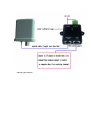
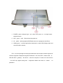
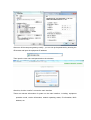
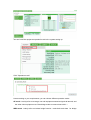
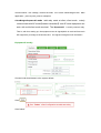
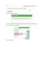
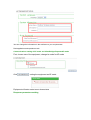
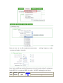
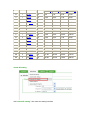
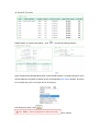
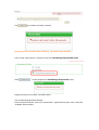
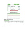
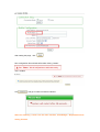
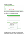
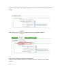
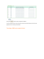
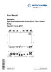
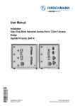
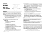
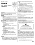
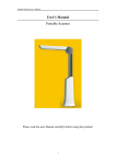
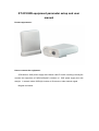
ST-2510AW equipment parameter setup and user
manual
Product appearance:
How to connect the equipment:
ST2510AW is POE power supply with network cable.To make it working normally,Pls
connect the equipment to PWR+DATA(OUT) interface of
POE power supply box with
straight in network cable, DATA(IN) connect to IP camera or other network signal.
Diagram as follows:
Indicator light diagram:
1, POWER, power indicator light,red,when POE power on,red light bright,
equipment start.
2, LAN,green,it will flicker when start power on.
3, AV,yellow,when equipment DATA(IN) connect to equipment,it will flicker
4, WLAN,green,it will be bright when equipment is under WDS bridge mode and
communication normally.
First,we should change the computer webmaster into the same network segment of
wireless equipment. Equipment original IP address is: 192.168.2.254,subnet mask is:
255.255.255.0,gateway:192.168.2.1,then the computer IP need to be:192.168.2.X
(X=2~253 any digital among this),equipment default user name is:Admin
password
.no
After turn off the computer gateway modify,you can set up the parameter by entering the
IE browser and input the equipment IP address:
Then input the user name and password on the windows:
After this, click the “confirm” to enter the main interface
These are relevant information of system on the main interface,including: equipment
operation mode, version information, network operating status, IP information, MAC
address, etc.
You can finish the equipment operation mode in the system setting up:
Click" Operation mode"
Here according to your requirements, you can choose different operation mode.:
AP mode(mainly refer to coverage, one mail equipment transmits signals all around, and
the other client equipment use Client bridge mode to communicate with it.)
WDS mode(mainly refer to wireless bridge function,make both ends data for bridge
communication,like a bridge, connect the ends,so it is also called bridge mode。Main
application:point-to-point, point-to multipoint)
ClientBridge+RepeaterAP mode(add relay mode at client, client mode
mainly
communicate with AP mode【master transmitter】,one AP mode equipment can
work with multi-client mode terminal。The RepeaterAP is mainly used as relay.
That is, with thus setting up, the equipment can do signal(which is received from main
AP equipment) coverage to all around, thus,the signal coverage area is increased.)
Equipment IP modify
Choose Local Area Network in the system default:
Click
Click”reboot”
Click
Enter restart count down interface
You will enter new IP interface after restart, then input the user name and password again.
Chang equipment’s user password
Click“management”
You can change the information in the red frame to your requirements.
Real application and operation mode
Communications setting of AP mode and ClientBridge+RepeaterAP mode
First, choose one of the equipment, change its mode for AP mode
Click
,setting the equipment as AP mode
Equipment will enter restart count down status
Response parameters settting
Here you can set up the equipment parameters: working frequency mode,
country and region, channels.
Here it aims at different working frequency to do multi-mode setting for equipment.
Under 802.11a / n mode and 802.11n mode,the MCS explanations as below:
MCS Spatial
index streams
Modulation
type
Coding
rate
Data rate (Mbit/s)
20 MHz channel
40 MHz channel
800 ns GI 400 ns GI 800 ns GI 400 ns GI
0
1
BPSK
1/2
6.50
7.20
13.50
15.00
1
1
QPSK
1/2
13.00
14.40
27.00
30.00
2
1
QPSK
3/4
19.50
21.70
40.50
45.00
3
1
16-QAM
1/2
26.00
28.90
54.00
60.00
4
1
16-QAM
3/4
39.00
43.30
81.00
90.00
5
1
64-QAM
2/3
52.00
57.80
108.00
120.00
6
1
64-QAM
3/4
58.50
65.00
121.50
135.00
7
1
64-QAM
5/6
65.00
72.20
135.00
150.00
8
2
BPSK
1/2
13.00
14.40
27.00
30.00
9
2
QPSK
1/2
26.00
28.90
54.00
60.00
10
2
QPSK
3/4
39.00
43.30
81.00
90.00
11
2
16-QAM
1/2
52.00
57.80
108.00
120.00
12
2
16-QAM
3/4
78.00
86.70
162.00
180.00
13
2
64-QAM
2/3
104.00
115.60
216.00
240.00
14
2
64-QAM
3/4
117.00
130.00
243.00
270.00
15
2
64-QAM
5/6
130.00
144.40
270.00
300.00
virtual AP setting
click“virtual AP setting”, then enter the setting interface
Default“VAP0” is in“start using”status,click
to insert the setting interface
Input corresponding identification name on the ESSID window. If it needs encryption, then
choose different encryption methods at the corresponding“safe mode”window, and write
the corresponding code on the right side of "sharing key"
After Setting this page, click
Click "reboott"
Click
, go to restart countdown interface:
Entering into main interface after restarting,
AP mode setting finished.
Then choose another device, change its mode into ClientBridge+RepeaterAP mode
Click
,set the equipment as ClientBridge+RepeaterAP mode.
Equipment will go to the restart countdown status
The corresponding parameter Settings
Enter the system interface, click on the "wireless set", appear the drop-down menu, select the
"available network search"
Appear network searching window:
After completion of a search will find network signal list, find out RSSID name you just set at
another AP mode equipment, click "select"
Operate on the appearing interface:
After setting this page , click
New configuration files will take effect after clicking "restart"
click " restartt"
Click
,and go to restart countdown interface
After the restarting ,it enter into the main interface, ClientBridge + RepeaterAP mode
setting finished.
Communication settings of WDS model
Select "operating mode"in the "system Settings" drop-down menu, choose "WDS model" in the
interface of pop-up
Click
, the system into the state of countdown restart
After login in, click on the "wireless set", select "general set"from the drop-down menu
The "general set" interface is mainly to set the wireless frequency band mode and channel:
Two sets of equipment to set up the mutual communication in the same channel, to carry out
normal communication, in the practical application of the user can set according to the actual
needs.
After setting, then click
, restart to make new configuration validation
Then enter the "WDS set" interface to set parameters
Basically to add the MAC address which communicate with it , maximum 8 group MAC
address
Finally click
,restart to make configuration validation.
The other equipment which communicate with it must do the same Settings, then the two sets
equipment can be normally communication
The setting of WDS mode complete finished