1
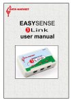
EASYSENSE 3Link
DO229 (1)
Each Smart Q Sensor incorporates a microprocessor that stores the calibration and autoidentification data. This dramatically simplifies set up procedures and allows for greater
flexibility when logging data.
Smart Q Sensors can be divided into two main types:
1. Analogue Sensors, which can be connected to any of the
three inputs on EASYSENSE 3Link. They will measure
physical changes such as light level, temperature and sound.
The physical value is converted into an electrical signal,
which is measured by EASYSENSE 3Link and
communicated to the computer.
Smart Q Sound Level sensor
2. Digital switch-type Sensors, which are capable of measuring
ON/OFF conditions.
Typical digital sensors include Light gates and Timing mats. If
used for timing investigations e.g. time, velocity and
acceleration relationships, these Sensors must be connected to
either Input 1:A or Input 1:A and 2:B.
Note: If used for analogue recording (e.g. using Graph), digital
sensors can be connected to any of the three inputs on EASYSENSE
3Link.
Smart Q Light Gate
Sensor inputs 1 to 3
(No 1 and 2 are dual labelled as A and B for timing applications)
The housing for most Smart Q Sensors is fitted with a mini DIN socket. The sensor leads
supplied are used to connect a Smart Q Sensor to EASYSENSE 3Link. For specific
instructions see the sensor’s user manual.
TE
t
ar
Sm
CH
NO
Q
GY
Smart Q label on top
LO
7
EST
RV
HA
© Data Harvest Group Ltd.
Locating arrows facing upwards
TA
DA
For the majority of Smart Q Sensors:
• Hold the sensor housing with
the Smart Q label showing on
the top.
Input socket
• Push one end of the sensor
cable into the shaped socket on
the sensor housing with the
Sensor cable
locating arrow on the cable
facing upwards.
• Connect the other end of the cable to the
input socket on EASYSENSE 3Link (with
the locating arrow facing upwards).