1
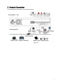
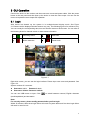
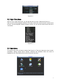
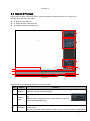
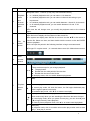
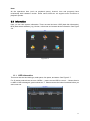
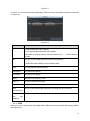
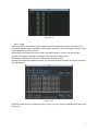
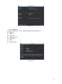
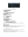
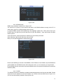
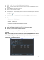
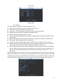
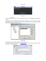
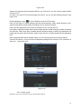
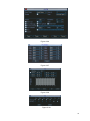
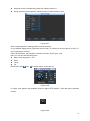
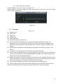
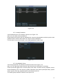
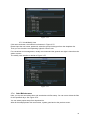
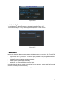
Network Video Recorder User Manual V 1.3.0 2 Table of Contents 1 Features and Specifications ...............................................................................................................1 1.1 Overview ........................................................................................................................................1 1.2 Features.........................................................................................................................................1 1.3 Specifications ................................................................................................................................2 1.4 Mouse Operation ..........................................................................................................................4 2 Network Connection ............................................................................................................................5 3 GUI Operation.......................................................................................................................................6 3.1 Login...............................................................................................................................................6 3.2 Right Click Menu ..........................................................................................................................7 3.3 Main Menu.....................................................................................................................................7 3.4 Search & Playback .......................................................................................................................8 3.5 Information .................................................................................................................................. 11 3.5.1 3.5.2 3.5.3 3.5.4 3.6 HDD Information .................................................................................................................. 11 BPS........................................................................................................................................12 Log .........................................................................................................................................13 Version ..................................................................................................................................14 Setting ..........................................................................................................................................15 3.6.1 General .................................................................................................................................15 3.6.2 Encode ..................................................................................................................................16 3.6.3 Schedule ...............................................................................................................................17 3.6.4 RS232 ...................................................................................................................................18 3.6.5 Network .................................................................................................................................19 3.6.5.1 Advanced Setup .........................................................................................................20 3.6.5.2 IP Filter .........................................................................................................................20 3.6.5.3 NTP Setup ...................................................................................................................21 3.6.5.4 Multiple Cast Setup ....................................................................................................21 3.6.5.5 PPPoE..........................................................................................................................22 3.6.5.6 DDNS Setup................................................................................................................23 3.6.5.7 UPNP ...........................................................................................................................23 3.6.5.8 Email ............................................................................................................................25 i 3.6.5.9 FTP ...............................................................................................................................26 3.6.5.1 Alarm center ................................................................................................................27 3.6.6 Alarm .....................................................................................................................................28 3.6.7 Detect ....................................................................................................................................30 3.6.8 PTZ ........................................................................................................................................33 3.6.9 Display ..................................................................................................................................35 3.6.10 Default ...................................................................................................................................36 3.6.11 Remote Device ....................................................................................................................37 3.6.11.1 Remote Device ...........................................................................................................37 3.6.11.2 Short-cut Menu .............................................................................................................38 3.7 Advanced.....................................................................................................................................39 3.7.1 HDD Management...............................................................................................................39 3.7.2 Abnormity..............................................................................................................................43 3.7.3 Alarm Output. .......................................................................................................................43 3.7.4 Manual Record.....................................................................................................................44 3.7.4.1 Manual record menu ..................................................................................................44 3.7.4.2 Basic operation................................................................................................................44 3.7.4.3 Enable/disable record ................................................................................................45 3.7.4.4 Enable all channel recording ....................................................................................45 3.7.4.5 Stop all channel recording.........................................................................................46 3.7.5 Account .................................................................................................................................46 3.7.5.1 Modify Password ........................................................................................................47 3.7.5.2 Add/Modify Group ......................................................................................................47 3.7.5.3 Add/Modify User .........................................................................................................48 3.7.6 Auto Maintenance ...............................................................................................................48 3.7.7 Config Backup......................................................................................................................49 3.8 4 Shutdown.....................................................................................................................................49 FAQ ......................................................................................................................................................51 ii Important Safeguards and Warnings 1.Electrical safety All installation and operation here should conform to your local electrical safety codes. We assume no liability or responsibility for all the fires or electrical shock caused by improper handling or installation. 2..Installation Keep upwards. Handle with care. Do not apply power to the NVR before completing installation. Do not place objects on the NVR 3.Qualified engineers needed All the examination and repair work should be done by the qualified service engineers. We are not liable for any problems caused by unauthorized modifications or attempted repair. 4.Environment The NVR should be installed in a cool, dry place away from direct sunlight, inflammable, explosive substances and etc. This series product shall be transported, storage and used in the environment ranging from 0 to 50 ℃ 5. Accessories Be sure to use all the accessories recommended by manufacturer. Before installation, please open the package and check all the components are included. Contact your local retailer ASAP if something is broken in your package. 6. Lithium battery Improper battery use may result in fire, explosion, or personal injury! When replace the battery, please make sure you are using the same model! iii 1 Features and Specifications 1.1 Overview This NVR is a high performance network video recorder. The NVR supports local preview, multiple-window display, local storage, mouse shortcut menu operation, remote management and control function. 1.2 Features User Management Storage Alarm Network Monitor Window Split Record Backup Network Management Peripheral Equipment Management ·Each group has different management powers that can be edited freely. Every user belongs to an exclusive group. Via corresponding setup (such as alarm setup and schedule setup), you can backup related audio/video data in the network video recorder. Support Web record and record local video and storage the file in the client end. Respond to external alarm simultaneously (within 200MS), based on user’s pre-defined relay setup, system can process the alarm input correctly and prompt user by screen and voice (support pre-recorded audio). Support central alarm server setup, so that alarm information can remotely notify user automatically. Alarm input can be derived from various connected peripheral devices. Alert you via EMAIL. Through network, sending audio/video data compressed by IPC or NVS to client-ends, then the data will be decompressed and display. If bandwidth is big enough, latency is less than 500ms Support max 10 connections Transmit audio/video data by HTTP, TCP, UDP, MULTICAST, RTP/RTCP and etc. Transmit some alarm data or alarm info by SMTP. Support WEB access in WAN. Adopt the video compression and digital process to show several windows in one monitor. Support 1/4/9/16-window display. Support schedule record function. Save the recorded files in the HDD, client-end PC, or network storage server. You can search or playback the saved files at the local-end or via the Web. Support network backup, USB record backup function, the recorded files can be saved in network storage server, peripheral USB device, burner and etc. Supervise NVR configuration and control power via Ethernet. Support management via WEB. Support peripheral equipment management such as protocol setup and port connection. Support transparent data transmission through RS232/RS485. 1 Auxiliary Support switch between NTSC and PAL. Support real-time system resources information and running statistics display. Support log file. Local GUI output. Shortcut menu operation via mouse. IR control function. Shortcut menu operation via remote control. Support IPC or NVS remote video preview and control. 1.3 Specifications Parameter System Resources Operation System Specification Max support 16-ch standard definition with the transmission rate of 2mbps for each channel; 8-channel 720P, with the transmission rate of 4mbps for each channel; 4-channel 1080P, with the transmission rate of 8mbps for each channel; Support 20 online users at the same time, The image delay time of each channel is under 500ms. Embedded Linux real-time operation system Operation Interface WEB/Local GUI Video Compression H.264/MPEG4 Encode Capacity For H.264, it max supports 16*D1, 8*720,4*1080P. Audio Compression G.711a Video Output 1-channel VGA analog video output. Video Input 4/8/16-ch network compression digital video input HDMI 1-ch HDMI output. Window Split 4/9/16-window Multiple-chann el Playback Max 16-channel playback. Alarm Input Alarm Output RS232 Port RS485 port 4/8/16-ch alarm input. Relay output. Relay (DC 30V 1A,AC 125V 0.5A(Activation output) ) Including one controllable DC +12V output. One RS232 port to debug transparent COM data. One RS485 port to control PTZ. Support various protocols. 2 USB Port 4 peripheral USB port. Network Connection One RJ45 10/100M/1000M self-adaptive Ethernet port. Power Button Power Button Clock One power button in the rear panel. One power button in the front panel. Built-in clock. Working Temperature 0℃~+50℃ Working Humidity 10℅-90℅ Air pressure 86kpa-106kpa Dimension 440mm*300mm*42.6mm Weight 1.5~2.5 KG(Exclude HDD) Installation Desk installation/Rack installation 3 1.4 Mouse Operation Please refer to the following sheet for mouse operation instruction. Left click mouse When you have selected one menu item, left click mouse to view menu content. Modify checkbox or motion detection status. Click combo box to pop up dropdown list In input box, you can select input methods. Left click the corresponding button on the panel you can input numeral/English character (small/capitalized). Here ← stands for backspace button. _ stands for space button. In English input mode: _stands for input a backspace icon and ← stands for deleting the previous character. In numeral input mode: _ stands for clear and previous numeral. ← stands for deleting the When input special sign, you can click corresponding numeral in the front panel to input. For example, click numeral 1 you can input“/” , or you can click the numeral in the on-screen keyboard directly. Double left click mouse Implement special control operation such as double click one item in the file list to playback the video. In multiple-window mode, double left click one channel to view in full-window. Double left click current video again to go back to previous multiple-window mode. Right click mouse In real-time monitor mode, pops up shortcut menu. Press middle button In numeral input box: Increase or decrease numeral value. Move mouse Select current control or move control Drag mouse Select motion detection zone Exit current menu without saving the modification. Switch the items in the check box. Page up or page down Select privacy mask zone. 4 2 Network Connection The following figure is based on the 38 series product. Figure 2-1 5 3 GUI Operation Connect the device to the monitor and then connect a mouse and power cable. Click the power button at the rear panel and then boot up the device to view the video output. You can use the mouse to implement some simple GUI operation. 3.1 Login After device has booted up, the system is in multiple-channel display mode. See Figure 3-1.Please note the displayed window amount may vary. The following figure is for reference only. You can overlay the corresponding date, time and channel name on each screen. You can refer to the following sheet for channel record or alarm status information. 1 Recording status 3 Video loss 2 Motion detection 4 Camera lock Figure 3-1 Right click mouse, you can see the login interface. Please input user name and password. See Figure 3-2. System consists of 2 accounts: Username: admin. Password: admin. Username: default. Password: default. You can use USB mouse to input. Click to switch between numeral, English character (small/capitalized) and denotation. Note: For security reason, please modify password after you first login. Within 30 minutes, three times login failure will result in system alarm and five times login failure will result in account lock 6 Figure 3-2 3.2 Right Click Menu After you log in, right click mouse, you can see the short cut menu. Please see Figure 3-3. Here you can set local playback window, PTZ control, video color, search records, remote device and etc. The local playback window includes 1/4/9/16. You can set the detail channel amount in 1/4-window. Figure 3-3 3.3 Main Menu The system main menu is shown as below. See Figure 3-4. There are total seven icons: search, Information, setting, remote device, backup, advanced and shutdown. Move the cursor to highlight the icon, then double click mouse to enter the sub-menu. 7 Figure 3-4 3.4 Search & Playback Click search button in the main menu, search interface is shown as below. See Figure 3-5. Usually there are three file types: R: Regular recording file. A: External alarm recording file. M: Motion detection recording file. 2 1 3 4 11 7 6 5 10 8 12 9 Figure 3-5 Please refer to the following sheet for more information. SN 1 2 3 Name Display window Search type Calendar Function This will display the searched picture or file. Support 1/4/9/16-window playback. Here you can select to search the picture or the recorded file. When there is displayed picture on the left pane, you can set the corresponding setup The blue highlighted date means there is picture or file. Otherwise, there is no picture or file. In any play mode, click the date you want to see, you can see the corresponding 8 record file trace in the time bar. Playback mode:1/4/9/16. (It may vary due to different series.) 4 5 Playback mode and channel selection pane. File list switch button In 1-window playback mode: you can select 1-16 channels. In 4-window playback mode: you can select 4 channels according to your requirement. In 9-window playback mode, you can switch between 1-9 and 10-16 channels. In 16-window playback mode, you can switch between1-16 and 17-32 channels. The time bar will change once you modify the playback mode or the channel option. Double click it, you can view the picture/record file list of current day. The file list is to display the first channel of the record file. The system can display max 128 files in one time. Use the / or the mouse to view the file. Select one item, and then double click the mouse or click the ENTER button to playback. You can input the period in the following interface to begin accurate search. File type:R—regular record; A—external alarm record;M—Motion detect record. 6 7 Card number search Playback control pane. The card number search interface is shown as below. ►/ Play/Pause There are three ways for you to begin playback. The play button Double click the valid period of the time bar. Double click the item in the file list. In slow play mode, click it to switch between play/pause. ■ Stop Backward play In normal play mode, left click the button, the file begins backward play. Click it again to pause current play. In backward play mode, click ►/ to restore normal play. │/ │ In playback mode, click it to play the next or the previous section. You can click continuously when you are watching the files from the same channel. In normal play mode, when you pause current play, you can click │ and │ to begin frame by frame playback. In frame by frame playback mode, click ►/ to restore normal playback. ► Slow play In playback mode, click it to realize various slow play modes such as slow play 1, slow play 2, and etc. 9 Fast forward In playback mode, click to realize various fast play modes such as fast play 1,fast play 2 and etc. Note: The actual play speed has relationship with the software version. Smart search The volume of the playback 8 9 10 Time bar Click the snapshot button in the full-screen mode, the system can snapshot 1 picture per second. It is to display the record type and its period in current search criteria. In 4-window playback mode, there are corresponding four time bars. In other playback mode, there is only one time bar. Use the mouse to click one point of the color zone in the time bar, system begins playback. The time bar is beginning with 0 o'clock when you are setting the configuration. The time bar zooms in the period of the current playback time when you are playing the file. The green color stands for the regular record file. The red color stands for the external alarm record file. The yellow stands for the motion detect record file. Time bar unit ●The option includes: 24H, 12H, 1H and 30M. The smaller the unit, the larger the zoom rate. You can accurately set the time in the time bar to playback the record. The time bar is beginning with 0 o'clock when you are setting the configuration. The time bar zooms in the period of the current playback time when you are playing the file. Backup Select the file(s) you want to backup from the file list. System max supports files from four channels. Then click the backup button, now you can see the backup menu. Click the start button to begin the backup operation. Check the file again you can cancel current selection. System max supports to display 32 files from one channel. 11 Clip 12 Record type Editing File. ●Please play the file you want to edit and then click this button when you want to edit. You can see the corresponding slide bar in the time bar of the corresponding channel. You can adjust the slide bar or input the accurate time to set the file end time. Click this button again and then save current contents in a new file. . In any play mode, the time bar will change once you modify the search type. Other Functions 13 Digital zoom When the system is in full-screen playback mode, left click the mouse in the screen. Drag your mouse in the screen to select a section and then left click mouse to realize digital zoom. You can right click mouse to exit. 10 Note: All the operations here (such as playback speed, channel, time and progress) have relationship with hardware version. Some series NVRs do not support some functions or playback speeds. 3.5 Information Here you can view system information. There are total six items: HDD (hard disk information), BPS (data stream statistics), log, Version, online user and remote device information. See Figure 3-6. Figure 3-6 3.5.1 HDD Information This menu lists the hard disk type, total space, free space, and status. See Figure 3-7. For 32 series product there are max 2 HDDs. ○ means current HDD is normal... - Means there is no HDD. If disk is damaged, system shows as “?”. Please remove the broken hard disk before you add a new one. 11 Figure 3-7 In Figure 3-7, click view recording time button, HDD record time information interface is shown as in Figure 3-8. Figure 3-8 Parameter Function SATA 1-4 here means there are 4 HDDS. For 32 series product there are max 2 HDDs. When HDD is working properly, system is shown as O. . “_” means there is no HDD. SN You can view the HDD amount the device connected to; ﹡ means the second HDD is current working HDD. Type The corresponding HDD property. Total space The HDD total capacity. Free space The HDD free capacity. Status HDD can work properly or not. Page up Click it to view previous page. Page down Click it to view the next page. View recording time Click it to view HDD record information (file start time and end time). View HDD type and capability Click it to view HDD property, status and etc, 3.5.2 BPS Here is for you to view current video data stream (KB/s) and occupied hard disk storage (MB/h). See Figure 3-9. 12 Figure 3-9 3.5.3 Log Here is for you to view system log file. System lists the following information. See Figure 3-10. Log types include system operation, configuration operation, data management, alarm event, record operation, log clear and etc. Please select start time and end time, then click search button. You can view the log files. System max displays 100 logs in one page. It can max save 1024 log files. Please page up/down button to view if there are more than ten files. System also supports the backup function; you can click the backup button to save the log files in the USB devices. Figure 3-10 Click the Details button or double click the log item, you can view the detailed information. See Figure 3-11. 13 Figure 3-11 3.5.4 Version This menu allows you to view version information. See Figure 3-12. Channel Alarm in Alarm out System version: Build Date Web Serial number Figure 3-12 14 3.6 Setting In main menu, highlight setting icon and double click mouse. System setting interface is shown as below. See Figure 3-13. Figure 3-13 Important Please note you need to have the proper rights to implement the following operation. 3.6.1 General General setting includes the following items. See Figure 5-3 . System time: Date format: There are three types: YYYYY-MM-DD: MM-DD-YYYYY or DD-MM-YYYY. Date separator: There are three denotations to separate date: dot, beeline and solidus. DST: Here you can set DST time and date. Please enable DST function and then cli ck set button. You can see an interface is shown as in Figure 3-15. Here you can set start time and end time by setting corresponding week setup. In Figure 3-15, enable date button, you can see an interface is shown as in Figure 5-5. Here you can set start time and end time by setting corresponding date setup. Time format: There are two types: 24-hour mode or 12-hour mode. Language: System supports various languages: Chinese (simplified), Chinese (Traditional), English, Italian, Japanese, French, Spanish HDD full: Here is for you to select working mode when hard disk is full. There are two options: stop recording or rewrite. If current working HDD is overwritten or the current HDD is full while the next HDD is no empty, then system stops recording, If the current HDD is full and then next HDD is not empty, then system overwrites the previous files. Pack duration: Here is for you to specify record duration. The value ranges from 60 to 120 minutes. Default value is 60 minutes. NVR No: When you are using one remote control (not included in the accessory bag) to control several NVRs, you can give a name to each NVR for your management. Video standard: There are two formats: NTSC and PAL. Auto logout: Here is for you to set auto logout interval once login user remains inactive for a specified time. Value ranges from 0 to 60 minutes. Startup wizard: Once you check the box here, system will go to the startup wizard directly when the system restarts the next time. Otherwise, it will go to the login interface. X357H357H357H X 15 Device ID: Please input a corresponding device name here. Figure 3-14 Figure 3-15 Figure 3-16 3.6.2 Encode Channel: Select the channel you want. Type: Please select from the dropdown list. There are three options: regular/motion detect/alarm. You can set the various encode parameters for different record types. Compression: System supports H.264. Resolution: The mainstream resolution type is IPC’s encoding configuration. Generally there is D1/720P/1080P. Frame rate: It ranges from 1f/s to 25f/s in NTSC mode and 1f/s to 30f/s in PAL mode. Bit rate type: System supports two types: CBR and VBR. In VBR mode, you can set video quality. Quality: There are six levels ranging from 1 to 6. The sixth level has the highest image quality. 16 Video/audio: You can enable or disable the video/audio. Overlay: Click overlay button, you can see an interface is shown in Figure 3-18. Cover area (Privacy mask): You can drag you mouse to set proper section size. In one channel video, system max supports 4 zones in one channel. Preview/monitor: privacy mask has two types. Preview and Monitor. Preview means the privacy mask zone cannot be viewed by user when system is in preview status. Monitor means the privacy mask zone cannot be view by the user when system is in monitor status. Time display: You can select system displays time or not when you playback. Please click set button and then drag the title to the corresponding position in the screen. Channel display: You can select system displays channel number or not when you playback. Please click set button and then drag the title to the corresponding position in the screen. Please highlight icon to select the corresponding function. Figure 3-17 Figure 3-18 3.6.3 Schedule In the main menu, from setting to schedule, you can go to schedule menu. See Figure 3-19. Channel: Please select the channel number first. You can select “all” if you want to set for the whole channels. Week day: There are eight options: ranges from Saturday to Sunday and all. Pre-record: System can pre-record the video before the event occurs into the file. The value ranges from 1 to 30 seconds depending on the bit stream. Redundancy: System supports redundancy backup function. It allows you backup recorded file in two disks. You can highlight Redundancy button to activate this function. Please note, 17 before enable this function, please set at least one HDD as redundant. (Main menu->Advanced->HDD Management) Snapshot: You can enable this function to snapshoot image when alarm occurs. Record types: There are four types: regular, motion detection (MD), Alarm, MD & alarm. Please highlight icon to select the corresponding function. After completing all the setups please click save button, system goes back to the previous menu. At the bottom of the menu, there are color bars for your reference. Green color stands for regular recording, yellow color stands for motion detection and red color stands for alarm recording. The white means the MD and alarm record is valid. Once you have set to record when the MD and alarm occurs, system will not record neither motion detect occurs nor the alarm occurs. Figure 3-19 Shortcut settings: Users can copy the settings of channel A to channel B to achieve the same configuration effect. E.g. choose channel 1 and click the copy button after relevant settings are done, then paste to channel3, you can find that the configuration of channel 3 is the same as that of channel 1. Users can save the configuration of each channel respectively or save the configuration all at once ultimately. 3.6.4 RS232 RS232 interface is shown as below. There are five items. See Figure 3-20. Function: There are various devices for you to select. Console is for you to use the COM or mini-end software to upgrade or debug the program. The control keyboard is for you to control the device via the special keyboard. Transparent COM (adapter) is to connect to the PC to transfer data directly. Protocol COM is for card overlay function. Network keyboard is for you to use the special keyboard to control the device. PTZ matrix is to connect to the peripheral matrix control. Baud rate: You can select proper baud rate. 18 Data bit: You can select proper data bit. The value ranges from 5 to 8. Stop bit: There are three values: 1/1.5/2. Parity: there are five choices: none/odd/even/space mark. System default setup is: Function: Console Baud rate:115200 Data bit:8 Stop bit:1 Parity: None After completing all the setups please click save button, system goes back to the previous menu. Figure 3-20 3.6.5 Network IP address: Input Internal IP Address DHCP: It is to auto search IP. When enable DHCP function, you cannot modify IP/Subnet mask /Gateway. These values are from DHCP function. If you have not enabled DHCP function, IP/Subnet mask/Gateway display as zero. You need to disable DHCP function to view current IP information. Besides, when PPPoE is operating, you cannot modify IP/Subnet mask /Gateway. TCP port: Default value is 37777. UDP port: Default value is 37778. HTTP port: Default value is 80. RTSP port: Default value is 554. Max connection: system support maximal 20 users. 0 means there is no connection limit. Preferred DNS server: DNS server IP address. Alternate DNS server: DNS server alternate address. Transfer mode: Here you can select the priority between fluency/video qualities. LAN download: System can process the downloaded data first if you enable this function. The download speed is 1.5X or 2.0X of the normal speed. After completing all the setups please click save button, system goes back to the previous menu. 19 Figure 3-21 3.6.5.1 Advanced Setup Advanced setup interface is shown as in Figure 3-22. Please draw a circle to enable corresponding function and then double click current item to go to setup interface. Figure 3-22 3.6.5.2 IP Filter IP filter interface is shown as in Figure 3-23. You can add IP in the following list. The list supports max 64 IP addresses. Please note after you enabled this function, only the IP listed below can access current NVR. If you disable this function, all IP addresses can access current NVR. Figure 3-23 20 3.6.5.3 NTP Setup You need to install SNTP server (Such as Absolute Time Server) in your PC first. In Windows XP OS, you can use command “net start w32time” to boot up NTP service. NTP setup interface is shown as in Figure 3-24. Host IP: Input your PC address. Port: This series NVR supports TCP transmission only. Port default value is 123. Update interval: minimum value is 1. Max value is 65535. (Unit: minute) Time zone: select your corresponding time zone here. Here is a sheet for your time zone setup. City /Region Name Time Zone London GMT+0 Berlin GMT+1 Cairo GMT+2 Moscow GMT+3 New Deli GMT+5 Bangkok GMT+7 Beijing (Hong Kong) GMT+8 Tokyo GMT+9 Sydney GMT+10 Hawaii GMT-10 Alaska GMT-9 Pacific Time(P.T) GMT-8 American Mountain Time(M.T) GMT-7 American Central Time(C.T) GMT-6 American Eastern Time(E.T) GMT-5 Atlantic Time GMT-4 Brazil GMT-3 Middle Atlantic Time GMT-2 Figure 3-24 3.6.5.4 Multiple Cast Setup Multiple-cast setup interface is shown as in Figure 3-25. 21 Figure 3-25 . Please refer to the following sheet for detailed information. IP multiple cast group address -224.0.0.0-239.255.255.255 -“D” address space The higher four-bit of the first byte=”1110” Reserved local multiple cast group address -224.0.0.0-224.0.0.255 -TTL=1 When sending out telegraph -For example 224.0.0.1 All systems in the sub-net 224.0.0.2 All routers in the sub-net 224.0.0.4 DVMRP router 224.0.0.5 OSPF router 224.0.0.13 PIMv2 router Administrative scoped addressees -239.0.0.0-239.255.255.255 -Private address space Like the single broadcast address of RFC1918 Can not be used in Internet transmission Used for multiple cast broadcast in limited space. Except the above mentioned addresses of special meaning, you can use other addresses. For example: Multiple cast IP: 235.8.8.36 Multiple cast PORT: 3666. After you logged in the Web, the Web can automatically get multiple cast address and add it to the multiple cast groups. You can enable real-time monitor function to view the view. Please note multiple cast function applies to special series only. 3.6.5.5 PPPoE PPPoE interface is shown as in Figure 3-26. Input “PPPoE name” and “PPPoE password” you get from your ISP (Internet service provider). Click save button, you need to restart to activate your configuration. After rebooting, NVR will connect to internet automatically. The IP in the PPPoE is the NVR dynamic value. You can access this IP to visit the unit. 22 Figure 3-26 3.6.5.6 DDNS Setup DDNS setup interface is shown as in Figure 3-27. You need a PC of fixed IP in the internet and there is the DDNS software running in this PC. In other words, this PC is a DNS (domain name server). In network DDNS, please select DDNS type and highlight enable item. Them please input your PPPoE name you get from you IPS and server IP (PC with DDNS ) . Click save button and then reboot system. Click save button, system prompts for rebooting to get all setup activated. After rebooting, open IE and input the domain name. Now you can open DDNSServer web search page. Figure 3-27 Please note NNDS type includes: CN99 DDNS、NO-IP DDNS、Private DDNS、Dyndns DDNS and sysdns DDNS. All the DDNS can be valid at the same time, you can select as you requirement. Private DDNS function shall work with special DDNS server and special Professional Surveillance Software (PSS). 3.6.5.7 UPNP The UPNP protocol is to establish a mapping relationship between the LAN and the WAN. Please input the router IP address in the LAN in Figure 3-21. Double click the UPNP item in Figure 3-21, you can see the following interface. See Figure 3-28. 23 UPNP on/off :Turn on or off the UPNP function of the device. Status: When the UPNP is offline, it shows as “Unknown”. When the UPNP works it shows “Success” Router LAN IP: It is the router IP in the LAN. WAN IP: It is the router IP in the WAN. Port Mapping list: The port mapping list here is the one to one relationship with the router’s port mapping setting. Enable Switch List: : :It shows that the function of port mapping is enabled in this port. Service name:Defined by user. Protocol: Protocol type Internal port:Port that has been mapped in the router. External port:Port that has been mapped locally. Default: UPNP default port setting is the HTTP, TCP and UDP of the NVR. Add to the list: Click it to add the mapping relationship. Delete: Click it to remove one mapping item. Double click one item; you can change the corresponding mapping information. See Figure 3-29. Important: When you are setting the routers external port, please use 1024~5000 port. Do not use well-known port 1~255 and the system port 256~1023 to avoid conflict. For the TCP and UDP, please make sure the internal port and external port are the same to guarantee the proper data transmission. 24 Figure 3-28 Figure 3-29 3.6.5.8 Email The email interface is shown as below. See Figure 3-30. SMTP server: Please input your email SMTP server IP here. Port: Please input corresponding port value here. User name: Please input the user name to login the sender email box. Password: Please input the corresponding password here. Sender: Please input sender email box here. Title: Please input email subject here. System support English character and Arabic number. Max 32-digit. Receiver: Please input receiver email address here. System max supports 3 email boxes. SSL enable: System supports SSL encryption box. Interval: The send interval ranges from 0 to 3600 seconds. 0 means there is no interval. Health email enable: Please check the box here to enable this function. This function allows the system to send out the test email to check the connection is OK or not. Interval: Please check the above box to enable this function and then set the corresponding interval. System can send out the email regularly as you set here. Click the Test button, you can see the corresponding dialogue box to see the email connection is OK or not. See Figure 3-31. Please note system will not send out the email immediately when the alarm occurs. When the alarm, motion detection or the abnormity event activates the email, system sends out the email according to the interval you specified here. This function is very useful when there are too many emails activated by the abnormity events, which may result in heavy load for the email server. 25 Figure 3-30 Figure 3-31 3.6.5.9 FTP You need to download or buy FTP service tool (such as Ser-U FTP SERVER) to establish FTP service. Please install Ser-U FTP SERVER first. From “start” -> “program” -> Serv-U FTP Server -> Serv-U Administator. Now you can set user password and FTP folder. Please note you need to grant write right to FTP upload user. See Figure 3-32. Figure 3-32 You can use a PC or FTP login tool to test setup is right or not. For example, you can login user ZHY to FTP://10.10.7.7 and then test it can modify or delete folder or not. See Figure 3-33. H140H 140H140HT U UTH 26 Figure 3-33 System also supports upload multiple NVRs to one FTP server. You can create multiple folders under this FTP. In Figure 3-21, select FTP and then double click mouse. You can see the following interface. See Figure 3-34. Please highlight the icon in front of Enable to activate FTP function. Here you can input FTP server address, port and remote directory. When remote directory is null, system automatically create folders according to the IP, time and channel. User name and password is the account information for you to login the FTP. File length is upload file length. When setup is larger than the actual file length, system will upload the whole file. When setup here is smaller than the actual file length, system only uploads the set length and auto ignore the left section. When interval value is 0, system uploads all corresponding files. After completed channel and weekday setup, you can set two periods for one each channel. Click the Test button, you can see the corresponding dialogue box to see the FTP connection is OK or not. See Figure 3-35. Figure 3-34 Figure 3-35 3.6.5.1 Alarm center Interface is pre-reserved for the users to develop this function. 27 3.6.6 Alarm In the main menu, from Setting to Alarm, you can see alarm setup interface. See Figure 3-36. Alarm setup: Alarm interface is shown as below. See Figure 3-36. Alarm in: Here is for you to select channel number. Event type: There are two types. One is local input and the other is network input. Type: normal open or normal close. PTZ activation: Here you can set PTZ movement when alarm occurs. Such as go to preset, tour& pattern when there is an alarm. Click “select” button, you can see an interface is shown as in Figure 3-37. Period: Click set button, you can see an interface is shown as in Figure 3-38. Here you can set for business day and non-business day. In Figure 3-38, click set button, you can see an interface is shown as in Figure 3-39. Here you can set your own setup for business day and non-business day. Anti-dither: Here you can set anti-dither time. Show message: System can pop up a message to alarm you in the local host screen if you enabled this function. Alarm upload: System can upload the alarm signal to the network (including alarm centre) if you enabled current function. Send email: System can send out email to alert you when alarm occurs. Record channel: you can select proper channel to record alarm video (Multiple choices). At the same time you need to set alarm record in schedule interface (Main Menu->Setting->Schedule) and select schedule record in manual record interface (Main Menu->Advance->Manual Record). Latch: Here is for you to set proper delay duration. Value ranges from 10 to 300 seconds. System automatically delays specified seconds in turning off alarm and activated output after external alarm cancelled. Tour: Here you can enable tour function when alarm occurs. System supports one-window tour. Please go to chapter 5.3.9 Display for tour interval setup. Buzzer: Highlight the icon to enable this function. The buzzer beeps when alarm occurs. Please highlight icon to select the corresponding function. After setting all the setups please click save button, system goes back to the previous menu. 28 Figure 3-36 Figure 3-37 Figure 3-38 Figure 3-39 29 3.6.7 Detect Go to Detect Menu In the main menu, from Setting to Detect, you can see motion detect interface. See Figure 3-40.There is three detection types: motion detection, video loss, camera masking. Motion Detect Detection menu is shown as below. See Figure 3-40 Event type: from the dropdown list you can select motion detection type. Channel: select the channel to activate recording function once alarm occurred. Please make sure you have set MD record in encode interface(Main Menu->Setting->Schedule) and schedule record in manual record interface(Main Menu->Advanced->Manual Record) Latch: when motion detection complete, system auto delays detecting for a specified time. The value ranges from 10-300(Unit: second) Region: Click select button, the interface is shown as in Figure 3-41. Here you can set motion detection zone. There are 396(PAL)/330(NTSC) small zones. The green zone is current cursor position. Grey zone is the motion detection zone. Black zone is the disarmed zone. You can click Fn button to switch between the arm mode and disarm mode. In arm mode, you can click the direction buttons to move the green rectangle to set the motion detection zone. After you completed the setup, please click ENTER button to exit current setup. Do remember click save button to save current setup. If you click ESC button to exit the region setup interface system will not save your zone setup. Sensitivity: System supports 6 levels. The sixth level has the highest sensitivity. Show message: System can pop up a message to alarm you in the local host screen if you enabled this function. Alarm upload: System can upload the alarm signal to the network (including alarm centre) if you enabled current function. Send email: System can send out email to alert you when alarm occurs. PTZ activation: Here you can set PTZ movement when alarm occurs. Such as go to preset, tour &pattern when there is an alarm. Click “select” button, you can see an interface is shown as in Figure 3-42 . Period: Click set button, you can see an interface is shown as in Figure 3-43. Here you can set for business day and non-business day. In Figure 3-43 click set button, you can see an interface is shown as in Figure 3-44. Here you can set your own setup for business day and non-business day. Anti-dither: Here you can set anti-dither time. Alarm output: when alarm occurred, system enables peripheral alarm devices. Tour: Here you can enable tour function when alarm occurs. System one-window tour. Please go to chapter 5.3.9 Display for tour interval setup. X305H305H305H X Snapshot: You can enable this function to snapshoot image when alarm occurs. Please highlight icon to select the corresponding function. After all the setups please click save button, system goes back to the previous menu. Note: In motion detection mode, you can not use copy/paste to set channel setup since the video in each channel may not be the same. In Figure 3-41, you can left click mouse and then drag it to set a region for motion detection. Click 30 Fn to switch between arm/withdraw motion detection. After setting, click enter button to exit. Figure 3-40 Figure 3-41 Figure 3-42 31 Figure 3-43 Figure 3-44 Video Loss In Figure 3-40, select video loss from the type list. You can see the interface is shown as in Figure 3-45.This function allows you to be informed when video loss phenomenon occurred. You can enable alarm output channel and then enable show message function. Tips: You can enable preset activation operation when video loss occurs. Figure 3-45 Camera Masking 32 When someone viciously masks the lens, or the output video is in one-color due to the environments light change, the system can alert you to guarantee video continuity. Camera masking interface is shown as in Figure 3-46. Note: In Detect interface, copy/paste function is only valid for the same type, which means you cannot copy a channel setup in video loss mode to camera masking mode. Figure 3-46 3.6.8 PTZ Note: All the operations here are based on PELCOD protocol. For other protocols, there might be a little difference. Cable Connection Please follow the procedures below to go on cable connection Connect the dome RS485 port to NVR 485 port. Connect dome video output cable to NVR video input port. Connect power adapter to the dome. PTZ Setup Note: The camera video should be in the current screen. Before setup, please check the following connections are right: PTZ and decoder connection is right. Decoder address setup is right. Decoder A (B) line connects with NVR A (B) line. Boot up the NVR, input user name and password. In the main menu, click setting, and then click Pan/Tilt Control button. The interface is shown as in Figure 3-47. Here you can set the following items: Channel: select the current camera channel. Protocol: select corresponding PTZ protocol(such as PELCOD) Address: default address is 1. Baud rate: select corresponding baud rate. Default value is 9600. Data bits: select corresponding data bits. Default value is 8. 33 Stop bits: select corresponding stop bits. Default value is 1. Parity: there are three options: odd/even/none. Default setup is none. Figure 3-47 After completing all the setting please click save button. In one window display mode, right click mouse (click “Fn” Button in the front panel or click “Fn” key in the remote control). Click Pan/Tilt/Zoom, the interface is shown as below. See Figure 3-48. Here you can set the following items: Step: value ranges fro 1 to 8. Zoom Focus Iris Please click icon and to adjust zoom, focus and iris. Figure 3-48 In Figure 3-48, please click direction arrows to adjust PTZ position. There are total 8 direction arrows. Figure 3-49 34 Reference Sheet. Name Function key function Zoom Wide Focus Near Iris Close Shortcut key Function key function Far │ Far Shortcut Key ►│ Open 3.6.9 Display Display setup interface is shown as below. See Figure 3-50. Transparency: The value ranges from 128 to 255. Channel name: System max support 25-digit (The value may vary due to different series). Please note all your modification here only applies to NVR local end. You need to open web or client end to refresh channel name. Time display: You can select to display time or not when system is playback. Channel display: You can select to channel name or not when system is playback. Resolution: There are four options: 1280×1024(default),1280×720,1024×768,800×600. Please note the system needs to reboot to activate current setup. Enable tour: Activate tour function. Interval: System supports 1/4/8/9/16-window tour. Input proper interval value here. The value ranges from 5-120 seconds. In tour process, you can use mouse or click Shift to turn on window switch function. Stands for opening switch function, stands for closing switch function. Monitor tour type: System support 1/8-window tour. Alarm tour type: System support 1/8-window tour. Please highlight icon to select the corresponding function. After completing all the setups please click save button, system goes back to the previous menu. Figure 3-50 35 In Figure 3-50, click modify button after channel. You can see an interface shown as in Figure 3-51. Please note all your modification here applies to local end only. You need to refresh web or client-end to get the latest channel name. System max support 25-digital character. Figure 3-51 In tour mode, you can see the following interface. On the right corner, right click mouse or click shift button, you can control the tour. There are two icons: and stands for enabling window switch stands for disabling window function. See Figure 3-52. Figure 3-52 3.6.10 Default Click default icon, system pops up a dialogue box. You can highlight to restore default factory setup. Select all General Encode Schedule RS232 Network Alarm Detect Pan/tilt/zoom Display Channel name Please highlight icon to select the corresponding function. After all the setups please click OK button, system goes back to the previous menu. Warning! System menu color, language, time display mode, video format, IP address, user account will not 36 maintain previous setup after default operation! 3.6.11 Remote Device 3.6.11.1 Remote Device In the main menu, click the Remote Device icon to go to the corresponding interface. See Figure 3-53. Figure 3-53 The remote device interface is shown as in Figure 3-54. IP search: Click it to search IP address. Add: Click it to connect to the selected device and add it to the Added device list. Support Batch add. Show filter: You can use it to display the specified devices from the added device. Delete: Please select one device in the Added device list and then click it to remove. Manual add: Click it to add the IPC manually. The port number is 37777. The default user name is admin and password is admin. 37 Figure 3-54 Click the Manual Add button; you can go to the following interface. See Figure 3-55. This series product max supports 16-channel standard definition video/high definition non-real-time video and the transmission rate is 2mbps per channel. It can also max supports 4-channel high definition video and the transmission rate is 8mbps. The delay time of each channel is below 500ms. Figure 3-55 3.6.11.2 Short-cut Menu In the preview interface, for the channel of no IPC connection, you can click the icon “+” in the centre of the interface to quickly go to the Remote Device interface. See Figure 3-56 and Figure 3-57. Figure 3-56 38 Figure 3-57 3.7 Advanced Double click advanced icon in the main window, the interface is shown as below. See Figure 3-58.There2 are total eight function keys: HDD management, alarm output, abnormity, manual record, account, auto maintenance, TV adjust and video matrix. Figure 3-58 3.7.1 HDD Management 39 Figure 3-59. You can see current HDD type, status, capacity and record time. When HDD is working properly, system is shown as O. When HDD error occurred, system is shown as X. Alarm set: Click alarm set button, the interface is shown as below. See Figure 3-60. (This interface is just like the abnormity setup). Please refer to chapter 6.7.2 for detailed information. HDD operation: You can select HDD mode from the dropdown list such as read-only or you can erase all data in the HDD. Please note system needs to reboot to get all the modification activated. Figure 3-59 Figure 3-60 For the HDD group setup operation, please note: Each channel’s records can be stored into the specified HDD Group. Each HDD Group is corresponding to several hard disks, while one hard disk is only included in one HDD Group. Each channel is only corresponding with one HDD Group, while one HDD Group can store records from several channels. 40 HDD Group is only available for read-write HDD and self-defined disks, other types of hard disks cannot be set as HDD Group. Important: e-SATA also supports this function, you can manage e-SATA hard disk as local hard disk. Current series software version can only set the HDD group operation of the read-write HDDs. It is not for the redundancy HDD. HDD Setting Click the button “HDD Settings” at the top right corner of the Figure 3-59, system will pop up an interface as below. See Figure 3-61. The number of hard disk from 1 to 12 is shown in the “HDD No.” column. If there is a mark in the front of the number, it means this interface have access to the hard disk, otherwise it does not have access to the hard disk. The “HDD Group” column lists the HDD Group number of current hard disk. When you are setting the HDD Group, please check the box of the hard disk, and then choose the corresponding HDD Group number and save the settings. In Figure 3-61, you can see the system has two working hard disks at the 6th and 7th position, and the 6th position hard disk belongs to HDD Group 1, the 7th position hard disk belongs to HDD Group 2. Figure 3-61 In Figure 3-62, you can see the 6th and 7th position hard disks both belong to HDD Group 2. Important Once you change the HDD Group settings, system will pack the records and snapshots, and then reboot. 41 Figure 3-62 Channels Setting Click the button named with “Channels Settings” at the top right corner of the Figure 3-59, system will pop up an interface shown as in Figure 3-63. When you are setting the configurations of the channels setting, please select relevant channels first (such as channel 1 to 16), and then select the HDD Group NO. Please click the Save button to save current setup. The Figure 3-63 and Figure 3-64 show that channels 1 to 16 are associated to HDD Group NO 1, and channels 17 to 32 are associated to HDD Group NO 2. Therefore the records of channels 1 to 16 are stored into the hard disk(s) which belong to HDD Group NO 1, and the records of channels 17 to 32 are stored into the hard disk(s) which belong to HDD Group NO 2. Important Once you change the HDD Group settings, system will pack the records and snapshots, and then reboot. Figure 3-63 42 Figure 3-64 3.7.2 Abnormity Abnormity interface is shown as in Figure 3-65. Event type: There are several options for you such as disk error, no disk, disconnection, IP conflict and etc. Alarm output: Please select alarm activation output port (multiple choices). Latch: Here you can set corresponding delaying time. The value ranges from 10s-300s. System automatically delays specified seconds in turning off alarm and activated output after external alarm cancelled. Show message: system can pop up the message in the local screen to alert you when alarm occurs. Alarm upload: System can upload the alarm signal to the network (including alarm centre) if you enabled current function. Send email: System can send out email to alert you when alarm occurs. Buzzer: Highlight the icon to enable this function. The buzzer beeps when alarm occurs. Figure 3-65 3.7.3 Alarm Output. Please highlight icon to select the corresponding alarm output. After finishing the set up please click OK button, system goes back to the previous menu. See Figure 3-66. 43 Figure 3-66 3.7.4 Manual Record Note: You need to have proper rights to implement the following operations. Please make sure the HDD has been properly installed. 3.7.4.1 Manual record menu There are two ways for you to go to manual record menu. Right click mouse or in the main menu, Advanced->Manual Record. In live viewing mode, click record button in the front panel or record button in the remote control. Manual record menu is shown as in Figure 3-67. 3.7.4.2 Basic operation There are three statuses: schedule/manual/stop. Please highlight icon “ ○ ” to select corresponding channel. Manual: The highest priority. After manual setup, all selected channels will begin ordinary recording. Schedule: Channel records as you have set in recording setup (Main Menu->Setting->Schedule) Stop: All channels stop recording. Figure 3-67 44 3.7.4.3 Enable/disable record Please check current channel status: “○” means it is not in recording status, “●” means it is in recording status. You can use mouse or direction key to highlight channel number. See Figure 3-68. Figure 3-68 3.7.4.4 Enable all channel recording Highlight ○ below All, you can enable all channel recording. All channel schedule record Please highlight “ALL” after “Schedule”. See Figure 3-69. When system is in schedule recording, all channels will record as you have previously set (Main menu->Setting->Schedule). The corresponding indication light in front panel will turn on. Figure 3-69 All channel manual record Please highlight “ALL” after “Manual.” See Figure 3-70. When system is in manual recording, all scheduled set up you have set in will be null ((Main menu->Setting->Schedule)). You can see indication light in front panel turns on, system begins manual record now. Figure 3-70 45 3.7.4.5 Stop all channel recording Please highlight “ALL” after “Stop”. See Figure 3-71. System stops all channel recording no matter what mode you have set in the menu (Main menu->Setting->Schedule) Figure 3-71 3.7.5 Account Figure 3-72. Add new user Modify user Add group Modify group Modify password. For account management please note: For the user account name and the user group, the string max length is 6-byte. The backspace in front of or at the back of the string is invalid. There can be backspace in the middle. The string includes the valid character, letter, number, underline, subtraction sign, and dot. System account adopts two-level management: group and user. No limit to group or user amount. For group or user management, there are two levels: admin and user. The user name and group name can consist of eight bytes. One name can only be used once. There are four default users: admin/888888/666666 and hidden user “default”. Except user 6666, other users have administrator right. Hidden user “default” is for system interior use only and can not be deleted. When there is no login user, hidden user “default” automatically login. You can set some rights such as monitor for this user so that you can view some channel view without login. One user should belong to one group. User right cannot exceed group right. About reusable function: this function allows multiple users use the same account to login. After all the setups please click save button, system goes back to the previous menu. 46 Figure 3-72 3.7.5.1 Modify Password Click password button, the interface is shown as in Figure 3-73. Here you can modify account password. Please select the account from the dropdown list, input the old password and then input the new password twice. Click the Save button to confirm current modification. For the users of user account right, it can modify password of other users. Figure 3-73 3.7.5.2 Add/Modify Group Click add group button, the interface is shown as below. See Figure 3-74. Here you can input group name and then input some memo information if necessary. There are total 60 rights such as control panel, shut down, real-time monitor, playback, record, record file backup, PTZ, user account, system information view, alarm input/output setup, system setup, log view, clear log, upgrade system, control device and etc. The modify group interface is similar to the Figure 3-74. 47 Figure 3-74 3.7.5.3 Add/Modify User Click add user button, the interface is shown as in Figure 3-75. Please input the user name, password, select the group it belongs to from the dropdown list. Then you can check the corresponding rights for current user. For convenient user management, usually we recommend the general user right is lower than the admin account. The modify user interface is similar to Figure 3-75. Figure 3-75 3.7.6 Auto Maintenance Here you can set auto-reboot time and auto-delete old files setup. You can set to delete the files for the specified days. See Figure 3-76. You can select proper setup from dropdown list. After all the setups please click save button, system goes back to the previous menu. 48 Figure 3-76 3.7.7 Config Backup The configuration file backup interface is shown as below. See Figure 3-77. This function allows you to copy current system configuration to other devices. Figure 3-77 3.8 Shutdown Double click shutdown button, system pops up a dialogue box for you to select. See Figure 3-78. Logout menu user: log out menu. You need to input password when you login the next time. Restart application: reboot device. Shutdown: system shuts down and turns off power. Restart system: system begins rebooting. Switch user: you can use another account to login. If you shut down the device, there is a process bar for your reference, system waits for 3 seconds and then shut down (You can not cancel). Please note, sometimes you need to input the proper password to shut down the device. 49 Figure 3-78 50 4 FAQ 1. Device wont boot up properly. There are following possibilities: Input power is not correct. Power connection is not correct. Power switch button is damaged. HDD malfunction or something wrong with HDD ribbon. Seagate DB35.1,DB35.2,SV35 or Maxtor 17-g has compatibility problem. Please upgrade to the latest version to solve this problem. Front panel error. Main board is damaged. 2. Device often automatically shuts down or stops running. There are following possibilities: Input voltage is not stable or it is too low. HDD malfunction or something wrong with the ribbon. Button power is not enough. Front video signal is not stable. Working environment is too harsh, too much dust. Hardware malfunction. 3. System cannot detect hard disk. There are following possibilities: HDD is broken. HDD ribbon is damaged. HDD cable connection is loose. Main board SATA port is broken. 4. There is no video output whether it is one-channel, multiple-channel or all-channel output. There are following possibilities: Program is not compatible. Please upgrade to the latest version. Brightness is 0. Please restore factory default setup. There is no video input signal or it is too weak. Check privacy mask setup or your screen saver. Device hardware malfunctions. 5. Real-time video color is distorted. There are following possibilities: When using BNC output, NTSC and PAL setup is not correct. The real-time video becomes black and white. Device and monitor resistance is not compatible. Video transmission is too long or degrading is too huge. Device color or brightness setup is not correct. 51 6. Cannot search local records. There are following possibilities: HDD ribbon is damaged. HDD is broken. Upgraded program is not compatible. The recorded file has been overwritten. Record function has been disabled. 7. Video is distorted when searching local records. There are following possibilities: Video quality setup is too low. Program read error, bit data is too small. There is mosaic in the full screen. Please restart the device to solve this problem. HDD data ribbon error. HDD malfunction. Device hardware malfunctions. 8. There is no audio when monitor. There are following possibilities: It is not a power picker. It is not a power acoustics. Audio cable is damaged. Device hardware malfunctions. 9. There is audio when monitor but there is no audio when system playback. There are following possibilities: Setup is not correct. Please enable audio function Corresponding channel has no video input. Playback is not continuous when the screen is blue. 10. Time display is not correct. There are following possibilities: Setup is not correct Battery contact is not correct or voltage is too low. Crystal is broken. 11. Device cannot control PTZ. There are following possibilities: Front panel PTZ error PTZ decoder setup, connection or installation is not correct. Cable connection is not correct. PTZ setup is not correct. PTZ decoder and device protocol is not compatible. PTZ decoder and device address is not compatible. 52 When there are several decoders, please add 120 Ohm between the PTZ decoder A/B cables furthest end to delete the reverberation or impedance matching. Otherwise the PTZ control is not stable. The distance is too far. 12. Motion detection function does not work. There are following possibilities: Period setup is not correct. Motion detection zone setup is not correct. Sensitivity is too low. For some versions, there is hardware limit. . 13. There is only mosaic no video when preview or playback video file remotely. There are following possibilities: Network fluency is not good. Client-end resources are limit. There is multiple-cast group setup in device. This mode can result in mosaic. Usually we do not recommend this mode. There is privacy mask or channel protection setup. Current user has no right to monitor. Device local video output quality is not good. 14. Burn error /USB back error. There are following possibilities: Burner and device are in the same data cable. System uses too much CPU resources. Please stop record first and then begin backup. Data amount exceeds backup device capacity. It may result in burner error. Backup device is not compatible. Backup device is damaged. 15. Keyboard cannot control device. There are following possibilities: Device serial port setup is not correct Address is not correct When there are several switchers, power supply is not enough. Transmission distance is too far. 16. Alarm signal cannot be disarmed. There are following possibilities: Alarm setup is not correct. Alarm output has been open manually. Input device error or connection is not correct. 53 17. Alarm function is null. There are following possibilities: Alarm setup is not correct. Alarm cable connection is not correct. Alarm input signal is not correct. There are two loops connect to one alarm device. 18. Record storage period is not enough. There are following possibilities: Camera quality is too low. Lens is dirty. Camera is installed against the light. Camera aperture setup is not correct. HDD capacity is not enough. HDD is damaged. 19. Cannot playback the downloaded file. There are following possibilities: There is no media player. No DXB8.1 or higher graphic acceleration software. There is no DivX503Bundle.exe control when you play the file transformed to AVI via media player. No DivX503Bundle.exe or ffdshow-2004 1012 .exe in Windows XP OS. 20. There is no video. The screen is black. There are following possibilities: IPC IP address is not right. IPC port number is not right. IPC account (user name/password) is not right. 21. The displayed video is not complete. Please cheek current resolution setup. If the current setup is 1920*1080, then you need to set the monitor resolution as 1920*1080. 22. There is no HDMI output. There are following possibilities: Displayer is not in HDMI mode. HDMI cable connection is not right. 54 23. The video is not fluent when I view in multiple-channel mode from the client-end. There are following possibilities: The network bandwidth is not sufficient. The multiple-channel monitor operation needs at least 100M or higher. Your PC resources are not sufficient. For 16-ch remote monitor operation, the PC shall have the following environment: Quad Core, 2G or higher memory, independent displayer, display card memory 256M or higher. Daily Maintenance Please use the brush to clean the board, socket connector and the chassis regularly. The device shall be soundly earthed in case there is audio/video disturbance. Keep the device away from the static voltage or induced voltage. 143H143H Please unplug the power cable when you remove the audio/video signal cable, RS232 or RS485 cable. Always shut down the device properly. Please press the power button in the front panel for at least three seconds to shut down the device. Otherwise it may result in HDD malfunction. Please make sure the device is away from the direct sunlight or other heating sources. Please keep the sound ventilation. Please check and maintain the device regularly. 55