1
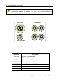
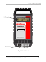
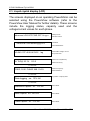
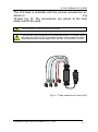
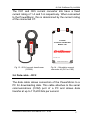
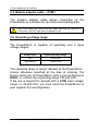
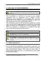
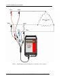
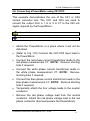
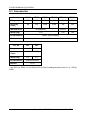
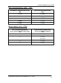
PowerMonic MODEL–PM20/PM30XX USER MANUAL © CHK GridSense Pty Ltd 2004 © CHK GridSense Pty Ltd 2004 PowerMonic PM20 / PM30 User Manual, Version 5.3 This product complies with IEC 61010 The material presented in this manual is copyright protected by CHK GridSense Pty Ltd 2004. Any reproduction in whole or part for any purpose without the prior written consent of CHK GridSense Pty Ltd is strictly prohibited. Information in this document is subject to change without notice. The photograph in Fig 15 is provided with the courtesy of Country Energy. All trademarks are property of their respective owners. Printed in Australia AUSTRALIA / NEW ZEALAND N3207 This is a Class A product. In a domestic environment this product may cause radio interference, which the user may need to take steps to prevent. 2 PowerMonic PM20/30xx User Manual V5.3 – 0704 © CHK GridSense Pty Ltd 2004 LIMITED WARRANTY The PowerMonic is guaranteed to be free of mechanical and electrical defects when dispatched from our store. Provided that the PowerMonic has been operated within its normal ratings as specified, it will be repaired or replaced free of charge if, within a period of twelve (12) months from date of our invoice to the original purchase, it is proven, upon examination by our engineers, to be defective in material or workmanship. This warranty is void if the unit has been tampered with, abused or if the defect is related to service not performed by CHK GRIDSENSE Pty Ltd. Responsibility of CHK GRIDSENSE Pty Ltd: Under this guarantee, it is limited to the repairing or replacing of any defective part and the instrument is returned freight paid to and from our Testing and Service office, Sydney. PowerMonic PM20/30xx User Manual V5.3 – 0704 3 © CHK GridSense Pty Ltd 2004 TABLE OF CONTENTS 1. THE POWERMONIC PM20/PM30 ..........................................6 2. POWERMONIC KIT OVERVIEW .............................................7 2.1. Liquid crystal display (LCD) 2.2. Voltage leads 10 11 2.2.1. Single Phase lead –PC4 11 2.2.2. Three phase 4-wire lead – VL4 12 2.2.3. Three phase 3-wire lead – VL3 13 2.2.4. Three phase 6-wire lead – VL6 14 2.3. Current transformer leads 2.4. Data cable – RC2 2.5. Modem adaptor cable – PCM1 2.6. Operating voltage range 16 17 18 18 3. SAFE USE OF THE POWERMONIC .....................................19 3.1. Hazard assessment 19 3.1.1. Live low voltage work 20 3.1.2. Equipment safety 21 3.2. IEC 61010 Measurement Category 24 4. CONFIGURING THE POWERMONIC BEFORE USE ..........25 5. INSTALLING YOUR POWERMONIC ....................................27 5.1. Pre-installation checks 5.2. Warranty cards 5.3. Securing the PowerMonic with the holster and strap 5.4. Connecting a PowerMonic to a 3-phase 4-wire system 5.5. Connecting a PowerMonic to a 3-phase 3-wire system 5.6. Connecting a PowerMonic using CK1/CK5 27 28 28 30 32 35 6. POWERMONIC PM20/30 SPECIFICATIONS .......................38 6.1. Accessories 40 7. TROUBLESHOOTING............................................................42 7.1. The PowerMonic does not start up after applying power: 42 7.2. The PowerMonic does not display the Voltage / current values:42 7.3. The PowerMonic displays the voltage/current values as zero: 42 4 PowerMonic PM20/30xx User Manual V5.3 – 0704 © CHK GridSense Pty Ltd 2004 7.4. The PowerMonic displays incorrect voltage/current values: 43 7.6. The PowerMonic does not communicate with the PC using the PowerView software: 44 7.7. The PowerMonic date and time are not correct: 44 8. USER NOTES.........................................................................45 9. CHK GRIDSENSE SUPPORT SERVICES ............................46 10. INDEX....................................................................................47 PowerMonic PM20/30xx User Manual V5.3 – 0704 5 © CHK GridSense Pty Ltd 2004 1. THE POWERMONIC PM20/PM30 Congratulations! You are a proud owner of a PowerMonic PM20/PM30 – state of the art analysers and data loggers for power supplies. International Safety Symbols: CAUTION Symbol: See explanation in manual This manual covers the PM20 and PM30. Other products in the PowerMonic suite are described in their relevant manual. CHK places the highest emphasis on safety. Please see section 3. SAFE USE OF THE POWERMONIC on page 19. Ensure that only qualified personnel use the PM20/PM30. This manual describes the installation and operation of the PM20 and PM30 three-phase power quality and disturbance analysers. Both units incorporate three-phase, three-channel voltage logging and three-phase, four channel current logging. The PM20 and PM30 log the RMS voltages and currents, harmonic voltages and currents, and power factor for each phase. Additionally, the PowerMonic can record transient RMS events on PM20 and PM30, and actual waveform data on the PM30. A summary of their logging capability is shown in the next page: 6 PowerMonic PM20/30xx User Manual V5.3 – 0704 © CHK GridSense Pty Ltd 2004 Logged Data PM20 PM30 RMS voltage and current ü ü 3 phase power factor ü ü Total harmonic distortion (THD) ü ü Individual harmonics up to 2400 Hz (48th harmonic) X ü Medium term disturbances (10 ms RMS data) ü ü Short term disturbances (digitised waveform signal) X ü Power system frequency as measured on the A phase ü ü PM20 PM30 kVA (3 phases) ü ü kW (3 phases) ü ü kVAR (3 phases) ü ü Derived Data 2. POWERMONIC KIT OVERVIEW The PowerMonic PM20 and PM30 family of equipment are listed below. The main instruments and their accessories are described in the following topics. Item Description 1 PowerMonic PM20 or PM30 unit 2 CK1 or CK5 substation current converter kit 3 PC4 single phase lead 4 VL4 4-way three phase lead 5 VL3 3-way three phase lead 6 VL6 6-way three phase lead 6 RC2 data cable 8 PCM1 modem cable PowerMonic PM20/30xx User Manual V5.3 – 0704 7 © CHK GridSense Pty Ltd 2004 For safety reasons, use only CHK GridSense Pty Ltd accessories specifically designed for use with this product. The use of any other manufacturer's equipment is NOT recommended. VOLTAGE CURRENT RS232 Data A B C N Fig 1 – PowerMonic end connectors Connector VOLTAGE RS232 Data 8 Description 3 Phase 6 wire plus earth CAT III 440Volts Connection to PC or Serial input device CURRENT “A” Current Transformer (“A” Channel) CURRENT “B” Current Transformer (“B” Channel) CURRENT “C” Current Transformer (“C” Channel) CURRENT “N” Current Transformer (“N” Channel) PowerMonic PM20/30xx User Manual V5.3 – 0704 © CHK GridSense Pty Ltd 2004 LCD display PowerMonic 3 Phase Power and Disturbance Analyser MODEL XXXX MADE IN AUSTRALIA Connectors Fig 2 – PowerMonic unit PowerMonic PM20/30xx User Manual V5.3 – 0704 9 © CHK GridSense Pty Ltd 2004 2.1. Liquid crystal display (LCD) The screens displayed on an operating PowerMonic can be selected using the PowerView software (refer to the PowerView User Manual for further details). These screens include the logging status, capacity used and the voltage/current values for each phase. hh:mm:ss LOG OFF PWR OFF Vx.yy.z Startup screen Firmware version ↓ 2 seconds hh:mm:ss LOG dd/mm/yyyy OFF Time/Date LOG ON/OFF/FULL ↓ 2 seconds VA 240.1 PF+0.99 IA 530.2 lag Phase A/B/C voltage, current and power factor ↓ 2 seconds N: THD(I) 35.1% 123.5 Neutral current (distortion) Neutral current (A) ↓ 2 seconds FREQ 50.01 PHASE IMB: 10.0% Phase A frequency Phase imbalance ↓ 2 seconds Log Status / Capacit y Used Data logging on: 13% full ↓ 2 seconds Waveform Capture on: 13% full Event Status ↓ 2 seconds RMS Capture on: 25% full Event Status ↓ 2 seconds Table Capture on: 31% full 10 Event Status PowerMonic PM20/30xx User Manual V5.3 – 0704 © CHK GridSense Pty Ltd 2004 Under certain conditions, the PowerMonic may display an error message screen. The possible error messages, causes and solutions are given in the table below. Error Message Cause Solution MAIN BATTERY LOW The battery used to power the PowerMonic has low voltage and should be replaced. Return the PowerMonic to your supplier for service. TIME BATTERY LOW The battery used to power the internal clock has low voltage and should be replaced. Return the PowerMonic to your supplier for service. 2.2. Voltage leads The voltage leads connect the PowerMonic to the equipment under test. Three types of leads are available: • PC4 single phase lead • VL4 three phase lead • VL3 three phase lead • VL6 three phase lead 2.2.1. Single Phase lead –PC4 The PC4 is supplied for use in the office or for single phase measurements. This lead has an internal earth connection. Fig 3 – Single phase lead (PC4) PowerMonic PM20/30xx User Manual V5.3 – 0704 11 © CHK GridSense Pty Ltd 2004 2.2.2. Three phase 4-wire lead – VL4 The VL4 is a four-way set (3 x active and 1 x common neutral). This lead is used for measurement of three-phase four-wire systems (Star or Wye configurations). This VL4 set is shown in Fig 4. This lead does not include an earth connection. Fuses should only be replaced by an authorised person. If in doubt, return the leads along with the full PowerMonic system to the supplier for repair. Replacement fuses must be rated to HRC 2A, 38 x 10.3mm, 500V 100kA. Fig 4 - Three phase lead to fuse (VL4) Fig 5 - Large clamps (AC4CL) 12 PowerMonic PM20/30xx User Manual V5.3 – 0704 © CHK GridSense Pty Ltd 2004 Fig 6 - Banana plugs with small clamp (AC4BC) 2.2.3. Three phase 3-wire lead – VL3 The VL3 is a three-way set (3 x active). This lead is used for measurement of three-phase three-wire systems (i.e. no neutral) such as Delta configurations. This VL3 set is shown in Fig 47. This lead does not include an earth connection. Fuses should only be replaced by an authorised person. If in doubt, return the leads along with the full PowerMonic system to the supplier for repair. Replacement fuses must be rated to HRC 2A, 38 x 10.3mm, 500V 100kA. Fig 7 - Three phase lead to fuse (VL3) PowerMonic PM20/30xx User Manual V5.3 – 0704 13 © CHK GridSense Pty Ltd 2004 Fig 8 - Large clamps (AC3CL) Fig 9- Banana plugs with small clam p (AC3BC) 2.2.4. Three phase 6-wire lead – VL6 The VL6 is a six-way set (3 x active and 3 x common neutral). This lead is used for measurement of three-phase three-wire systems (i.e. no neutral) such as Delta configurations as shown in Fig 10. When using the VL6 configuration, the three voltage channels are totally isolated from one another, so it may be used to monitor voltage sources that are floating with respect to each other. The working voltage between leads must not exceed 500 V RMS. 14 PowerMonic PM20/30xx User Manual V5.3 – 0704 © CHK GridSense Pty Ltd 2004 The VL6 lead is available with the various accessories as shown in Fig 101and Fig 12. The accessories are joined at the fuse holder end of the lead. This lead does not include an earth connection. Fuses should only be replaced by an authorised person. If in doubt, return the leads along with the full PowerMonic system to the supplier for repair. Replacement fuses must be rated to HRC 2A, 38 x 10.3 mm, 500 V 100 kA. Fig 10 - Three phase lead to fuse (VL6) PowerMonic PM20/30xx User Manual V5.3 – 0704 15 © CHK GridSense Pty Ltd 2004 Fig 11 - Large clamps (AC6CL) Fig 12 - Banana plugs with small clamp (AC6BC) 2.3. Current transformer leads The current transformer (CT) leads allow clip-on type connection to the current transformers or substation current converter units. The PowerMonic continuously detects the current rating of the clip on CTs while they are attached and adjusts the LCD accordingly. 16 PowerMonic PM20/30xx User Manual V5.3 – 0704 © CHK GridSense Pty Ltd 2004 The CK1 and CK5 current converter kits have a fixed current rating of 1 A and 5 A respectively. When connected to the PowerMonic, this is determined by the current rating of the connected CT. 3 PHASE 1A:200mA CONVERTER MODEL CK1 CR 500 M T Serial No. xxxxx MADE IN AUSTRALIA Fig 13 - 500 A current transformer (CR500) Fig 14 – Substation current converter kit (CK1 or CK5) 2.4. Data cable – RC2 The data cable allows connection of the PowerMonic to a PC for downloading data. This cable attaches to the serial communications (COM) port of a PC and allows data transfer at up to 115,200 bits per second. PowerMonic PM20/30xx User Manual V5.3 – 0704 17 © CHK GridSense Pty Ltd 2004 2.5. Modem adaptor cable – PCM1 The modem adaptor cable allows connection of the PowerMonic to a modem for remotely downloading data. This PCM1 cable only works one way. Make sure that the DB9 end is connected to the RC2 data cable (PowerMonic end). 2.6. Operating voltage range The PowerMonic is capable of operating over 2 input voltage ranges: Voltage Input Operating Voltage Range Low 63-260 VAC High (default) 125-440 VAC The operating range is clearly labelled on the PowerMonic. Unless otherwise specified at the time of ordering, the factory setting for all PowerMonic units is pre-configured at HIGH, i.e. normal input operating range 125-440 VAC. If the unit is required to operate with a LOW input voltage range, i.e. 63-260 VAC, you must return the PowerMonic to your supplier for reconfiguration. 18 PowerMonic PM20/30xx User Manual V5.3 – 0704 © CHK GridSense Pty Ltd 2004 3. SAFE USE OF THE POWERMONIC If you do not understand any instructions in this manual, ask someone to assist you. The PowerMonic is intended to be used on low voltage energised lines or equipment (415 V RMS or less). Personnel using equipment on energised lines must be authorised by the relevant regulatory bodies to carry out such work and must have appropriate training. The information given in this document is given as a guide only. It is the user's responsibility to ensure that correct and safe procedures are followed at the actual worksite. CHK offers no warranty or indemnity for accidents that may occur when following these instructions. The PowerMonic is rated at IEC61010 CAT III 440 Volts Be careful when the PowerMonic is connected to a voltage source using a three phase lead (VL4 or VL6) - it is not grounded. The PowerMonic and some types of voltage leads have internal HRC fuses. Do not attempt to replace these fuses in the field. Return the full PowerMonic system with the voltage leads to your supplier if you suspect a blown fuse. 3.1. Hazard assessment Prior to using the PowerMonic, the operator must carry out a worksite, pre-job hazard assessment to identify the safety and environmental needs. This must be done prior to commencing work and prior to recommencing work after leaving the worksite. PowerMonic PM20/30xx User Manual V5.3 – 0704 19 © CHK GridSense Pty Ltd 2004 This hazard assessment should: • • • • • • Identify possible hazards and risks. Identify the safety needs of the job. Identify the correct procedures, practices and equipment for the job. Eliminate unsafe conditions and actions from the worksite. Identify the need for personal protective clothing. Perform an ongoing risk assessment during the job. 3.1.1. Live low voltage work Check your relevant regulatory body's rules for working with live equipment. For the correct and safe use of this equipment, it is essential that all operating personnel follow these safe ty procedures. When using a PowerMonic on or near live low voltage conductors, the following basic safety principles should be observed. See Fig 1 for typical work sites. Apart from the conductor that you are working on, you must be insulated from earth and any other conductor or maintain a distance of at least 500 mm (or other distance as required by relevant legislation or live working rules) from those points. • • • • • 20 Use insulated matting to cover bare busbars and exposed metalwork. Use ground mats. Wear protective safety eyewear and a hard hat. You should be trained in first aid procedures and have a portable first aid kit on hand. If working alone, ensure that a responsible person knows that you are working on live line equipment and will initiate emergency action if you do not call in within a specified period. PowerMonic PM20/30xx User Manual V5.3 – 0704 © CHK GridSense Pty Ltd 2004 Fig 15 – Use of insulating mats in switchboard application • When connecting the voltage leads or CT tongs to the conductors, do not assume that the insulation on the handle is adequate insulation. You must wear an insulating glove on each hand. Ensure that the exposed metal parts of the voltage lead clamps do not contact other conductors and cause a short circuit. Insulating Gloves must be worn on each hand when handling voltage leads or CT tongs. 3.1.2. Equipment safety The PowerMonic equipment should be regularly tested and maintained to make sure the equipment and leads are in good order. INSPECTION BEFORE USE: Prior to using a PowerMonic, you should check the following: • No outer sheath of any lead is damaged, and no inner insulation is showing. • The sheaths of all leads are secured at the ends. PowerMonic PM20/30xx User Manual V5.3 – 0704 21 © CHK GridSense Pty Ltd 2004 • Plugs and connectors, including fuse holders are properly connected and serviceable. • The operating range, as indicated on the front of the PowerMonic, is suitable for the application. PERIODIC MAINTENANCE AND TESTING: The PowerMonic and leads should be inspected, tested and tagged on a regular basis (e.g. every 3 months). Testing should include: • Inspection (as above). • Insulation test conducted at 500 V DC between each phase conductor with a minimum acceptable level of insulation resistance of 1 MΩ. • A record of inspections should be kept that shows: • Date of inspection, plant number or inspection number for the PowerMonic/accessory. • Results of the tests and inspections and details of any repair work. • Signature of an authorised inspector. EQUIPMENT FAULTS: If the equipment is found to be faulty in any way, including blown fuses, it should be returned to your supplier for service. CALIBRATION: The equipment should be calibrated every 12 months. CLEANING YOUR EQUIPMENT: All equipment should be cleaned with a soft, moist cloth using only a mild detergent. 22 PowerMonic PM20/30xx User Manual V5.3 – 0704 © CHK GridSense Pty Ltd 2004 STANDBY BATTERY : The PowerMonic uses a sealed lead acid standby battery to power the unit when loss of AC supply occurs for two minutes to allow logging of waveforms etc. Like all Lead Acid batteries, the performance of the battery will degrade if it is exposed to long periods of high temperature and/or it is allowed to discharge excessively. The battery life of the PowerMonic can be exte nded by following a few simple precautions as outlined below: • When the PowerMonic is not in use it should be stored at ambient temperatures below 30o C • When the PowerMonic is not in use it should be stored with a fully charged battery. This can be achieved by: - Charge the battery by energising the PowerMonic for 24 hours before storage - Recharge the battery after every three months of non use - Recharge the battery after each use of the PowerMonic PowerMonic PM20/30xx User Manual V5.3 – 0704 23 © CHK GridSense Pty Ltd 2004 3.2. IEC 61010 Measurement Category Under the IEC 61010 standard, the location of the measured point determines the transient overvoltage stresses that may be imposed on the measuring equipment. This voltage is independent of the nominal working voltage (e.g. 240 volts) of the system The 4 Measurement Categories (also known as Overvoltage Categories) are: Measurement Category CAT I CAT II Description Measurements of circuits not directly connected to Mains Measurements performed on circuits directly connected to the low voltage installation CAT III Measurements performed in the building installation CAT IV Measurements performed at the source of the low voltage installation Examples Secondaries of low power transformers, Protected electronic equipment, Household appliance, portable tools and similar equipment Distribution boards, circuit breakers, wiring, bus -bars, switches, socket outlets, industrial equipment such as stationary motors permanently connected to the fixed installation Electricity Meters, overhead lines, primary overcurrent protection equipment, underground cables to remote equipment Under the IEC 61010 standard, Equipment is assigned a working voltage value (e.g. 300 Volts) and a measurement category which reflects the amount of overvoltage stress that the equipment can tolerate. This is expressed as a CAT number and associated working voltage value. The PowerMonic is rated at Measurement Category CAT III, 440 Volts. 24 PowerMonic PM20/30xx User Manual V5.3 – 0704 © CHK GridSense Pty Ltd 2004 4. CONFIGURING THE POWERMONIC BEFORE USE The PowerMonic is configured using a PC running CHK's PowerView software for Microsoft Windows. To install this software, refer to the PowerView User Manual. To connect the PowerMonic to the PC: 1. 2. 3. 4. 5. 6. 7. Connect the RC2 data cable to one of the COM ports on your PC (refer to your PC manual for details of your COM ports). You may need to use a 9-to-25 pin serial port adapter. After connecting the RC2 data cable to the PC, make a note of the serial connector you used (COM1, COM2, COM3, etc). You will need to know this when you run the PowerView software. Connect the PC4 single phase lead to the PowerMonic. Connect the RC2 data cable to the PowerMonic. Connect the PC4 single phase lead to the mains socket. Start the PowerView software. Refer to the PowerView User Manual for further operating information. You can now use PowerView to configure the PowerMonic. When configuration is complete, disconnect the PowerMonic from the PC and proceed with installation. PowerMonic PM20/30xx User Manual V5.3 – 0704 25 © CHK GridSense Pty Ltd 2004 To Mains Socket PC4 Single Phase Lead To PC COM port PowerMonic 3 Phase Power and Disturbance Analyser MODEL XXXX Data Cable MADE IN AUSTRALIA Fig 16 – Connecting the PowerMonic to the PC 26 PowerMonic PM20/30xx User Manual V5.3 – 0704 © CHK GridSense Pty Ltd 2004 5. INSTALLING YOUR POWERMONIC The PowerMonic must be installed in accordance with the relevant legislation and workplace OH&S guidelines. Refer to section 3. SAfe use of the PowerMonic for basic safety advice that should be followed if no other procedures apply. When connecting current transformers (CTs) to the PowerMonic, ensure that each CT is matched to the appropriate voltage channel (refer to the diagrams with the installation instructions). Australia Phase ID Voltage Lead Colour Current Transformer Channel A Red A B White B C Blue C Neutral Black N (Neutral) The voltage leads are colour-coded red, white and blue (A, B, and C phase) and are to be attached to corresponding phases. The PowerMonic is powered from the A phase connection. On VL4 type leads, the black lead is the neutral connection. 5.1. Pre-installation checks • • • Verify that the nominal voltage to be tested is within the operating range of the PowerMonic as indicated on the front label. Identify and test the neutral and all phases. Ensure that voltage leads and CT leads are secured and not likely to move or dislodge. PowerMonic PM20/30xx User Manual V5.3 – 0704 27 © CHK GridSense Pty Ltd 2004 • • • The PowerMonic is powered by A phase voltage. You must connect this phase for the PowerMonic to begin logging. Unus ed voltage leads should be connected to neutral or placed in an isolated container. (Do not leave the unit unattended with unconnected voltage clamps). The A phase must be able to provide 10 W to power the PowerMonic. 5.2. Warranty cards When you first install your PowerMonic, you should complete your warranty card and mail it (postage paid) to CHK GridSense Pty Ltd. 5.3. Securing the PowerMonic with the holster and strap When installing a PowerMonic, hang the instrument in a suitable location and ensure that it is safely secured using the holster and strap provided. Step 1. The strap is first fed through the holster slats and wrapped around the pole. 28 PowerMonic PM20/30xx User Manual V5.3 – 0704 © CHK GridSense Pty Ltd 2004 Step 2. Bring the strap forward to embrace the PowerMonic. Step 3. Wrap the strap around the post and secure the PowerMonic with the quick release clip at the rear. Note: Do not connect the PowerMonic PM20/30 to the pole without embracing the unit with the strap, as this may weaken the holster over time. PowerMonic PM20/30xx User Manual V5.3 – 0704 29 © CHK GridSense Pty Ltd 2004 5.4. Connecting a PowerMonic to a 3-phase 4-wire system Ensure all safety procedures are followed. This procedure assumes the use of a VL4 voltage lead. 1. Secure the PowerMonic to a safe position. 2. (Refer to Fig ) Connect the CTs to the PowerMonic, observing correct phase connections. 3. Connect the CTs to the conductors. Ensure that the arrow is pointing in the direction of the load. 4. Connect all voltage leads to the neutral conductor or place in an isolated bag. 5. Connect the neutral (black) lead to the neutral conductor. 6. Connect the red lead to the A phase conductor. 7. Connect the white lead to the B phase conductor. 8. Connect the blue lead to the C phase conductor. Unused voltage lead clamps should be connected to the neutral conductor Clamps will short live conductors. 9. Plug the free end of VL4 lead to PowerMonic. 10. Verify that PowerMonic starts up. Check the readings including the power factor to ensure correct connection of voltage leads and CTs (refer to Error! Reference source not found.). 30 PowerMonic PM20/30xx User Manual V5.3 – 0704 © CHK GridSense Pty Ltd 2004 11. If the power factor for any phase is displayed as a negative reading, carefully reverse the orientation of the CT for that phase. To remove the PowerMonic, perform these steps in the reverse order. Blue White To Load Red Black All arrows point must point in the direction of the load PowerMonic 3 Phase Power and Disturbance MODEL XXXX MADE IN AUSTRALIA Fig 17 - Connecting the PowerMonic to a 3-phase 4-wire system PowerMonic PM20/30xx User Manual V5.3 – 0704 31 © CHK GridSense Pty Ltd 2004 5.5. Connecting a PowerMonic to a 3-phase 3-wire system Ensure all safety procedures are followed. This procedure assumes the use of a VL6 voltage lead. 1. Secure PowerMonic to a safe position. 2. (Refer to Fig 18) Connect the CTs to the PowerMonic, observing correct phase connections. 3. Connect the CTs to the conductors. Ensure that the arrow is pointing in the direction of the load. 4. Connect all voltage leads to the neutral conductor or place in an isolated bag. 5. Connect the VL6 leads as follows: Lead ID VL6 Lead Colour Fuseholder Colour Conductor A Phase Active Red Red A A Phase Reference Black Black B B Phase Active White White B B Phase Reference Black Black C C Phase Active Blue Blue C C Phase Reference Black Black A 6. Connect the A phase reference to the B phase conductor. 7. Connect the A phase active to the A phase conductor. 8. Connect the B phase reference to the C phase conductor. 32 PowerMonic PM20/30xx User Manual V5.3 – 0704 © CHK GridSense Pty Ltd 2004 9. Connect the B phase active to the B phase conductor. 10. Connect the C phase reference to the A phase conductor. 11. Connect the C phase active to the C phase conductor. Unused voltage lead clamps should be connected to the neutral conductor 12. Plug the free end of VL6 lead to PowerMonic. 13. Verify that PowerMonic starts up. Check the readings including the power factor to ensure correct connection of voltage leads and CTs (refer to section Error! Reference source not found. ). 14. If the power factor for any phase is displayed as a negative reading, carefully reverse the orientation of the CT for that phase. To remove the PowerMonic, perform these steps in the reverse order. PowerMonic PM20/30xx User Manual V5.3 – 0704 33 © CHK GridSense Pty Ltd 2004 Fig 18 - Connecting the PowerMonic to a 3-phase 3-wire system 34 PowerMonic PM20/30xx User Manual V5.3 – 0704 © CHK GridSense Pty Ltd 2004 5.6. Connecting a PowerMonic using CK1/CK5 This example demonstrates the use of the CK1 or CK5 current converter kits. The CK1 and CK5 are used to convert the output from a 1 A or 5 A CT to the 200 mA signal required by the PowerMonic. Ensure all safety procedures are followed. This procedure assumes the use of a VL4 voltage lead. 1. Attach the PowerMonic in a place where it will not be disturbed. 2. (Refer to Fig 119) Connect the CK1/CK5 input lead to the PowerMonic. 3. Connect the red phase current transformer leads to the red phase measurement CT. NOTE: Remove shorting links if required. 4. Connect the white phase current transformer leads to the white phase measurement CT. NOTE: Remove shorting links if required. 5. Connect the blue phase current transformer leads to the blue phase measurement CT. NOTE: Remove shorting links if required. 6. Temporarily attach the four voltage leads to the neutral conductor. 7. Remove the red phase voltage lead from the neutral conductor. Attach the red phase voltage lead to the red phase conductor (this lead powers the PowerMonic). PowerMonic PM20/30xx User Manual V5.3 – 0704 35 © CHK GridSense Pty Ltd 2004 When the power on the red phase is first applied to the PowerMonic, the LCD will display the date and time. 8. Remove the white phase voltage lead from the neutral conductor. Attach the white phase voltage lead to the white phase conductor. 9. Remove the blue phase voltage lead from the neutral conductor. Attach the blue phase voltage lead to the blue phase conductor. 10. Connect the VL4 input lead to the PowerMonic. 11. If the power factor for any phase is displayed as a negative reading, swap the two leads connected to the banana sockets of the relevant phase of the CK1/CK5. WARNING: If necessary, replace the shorting link before swapping leads. To remove the PowerMonic, perform these steps in the reverse order. 36 PowerMonic PM20/30xx User Manual V5.3 – 0704 © CHK GridSense Pty Ltd 2004 CT (1A output) Blue (C) phase CT (1A output) (B) phase White CT (1A output) (A) phase Red Black Neutral phase ue Bl Red Wh ite PowerMonic 3 Phase Power and Distur bance Analyser 3 PHASE 1A:200mA CONVERTER MODEL CK1 M T 3 PHASE POWER & DISTURBANCE ANALYSER MODEL XXXX 3 PHASE POWER & DISTURBANCE ANALYSER PM30 MADE IN AUSTRALIA MADE IN AUSTRALIA Serial No. MADE IN AUSTRALIA Serial No 01813601 Made in Australia d Re it e Wh Blue Fig 19 – Connecting the PowerMonic using CK1/CK5 kits Leads and connectors are not supplied with the CK1 or CK5 current converter kits. PowerMonic PM20/30xx User Manual V5.3 – 0704 37 © CHK GridSense Pty Ltd 2004 6. POWERMONIC PM20/30 SPECIFICATIONS Voltage Current Input Channels 3 (isolated) 4 Measuring (RMS) 125-440 V 0-3000 A (max with clip-on CTs, others no limit) Range 63-260 V available on request Isolation Voltage between Channels 600 V RMS (not isolated between CT inputs) Power Frequency 40-70 Hz (50-60 Hz nominal) 40-70 Hz nominal) Instrument Accuracy 0.4% reading ± 1 lsd 0.4% reading ± 1 lsd System Accuracy 0.4% reading ± 1 lsd 1% reading (0.5M CTs) Resolution 0.1 V 0.1 A (0-500 1 A (1000-3000 A) System Instrument Input 0-200 mA CT Burden 2.2 Ω ± 1% (50-60 ± 1 IEC 61010-1 2001 Protection Levels Pollution Degree 2 Installation Category III Material Group III, 600 V Measurement Category III 440 Volts (Double Insulation or Reinforced Insulation) Connectors Environmental Voltage & Power 8 pin 30mm dia Temperature -10°C to + 60°C Current 4 pin circular Humidity 20% to 99% RH Data 5 pin circular Sealing IP65 38 PowerMonic PM20/30xx User Manual V5.3 – 0704 Hz lsd A) © CHK GridSense Pty Ltd 2004 Power Factor +1 to -1, Accuracy ± 0.01 ± 1 lsd Power (Real) Accuracy approx. 2% when used with class 0.5 M CTs Harmonics PM30: Logging from 1st to 48th, both even and odd PM20: Not Available Total Harmonic Distortion Accuracy ± 2% Sample Rate 11,413 samples per second (>228 / cycle at 50 Hz, >190 / cycle at 60 Hz) Logging Rate Normal RMS: 30 seconds to 4 hours (user selectable) Real Time Clock ± 50 ppm (2 min/month approx) Event Re cording (see table below) PM20: PM30: Power Source When Logging - A phase to Neutral, 125 – 440 V Rechargeable 6 V 0.5 Ah sealed lead acid battery backup for power outages Clock – ½ AA, 3 V Lithium Power Consumption 10 W typical (from A phase) Memory 4 Mb of non-volatile FLASH memory Communication RS-232 serial interface, software selectable to 115,200 baud Display 2 line x 16 character, scrolling selected screens every 2 seconds Information shown: date, time, 3 voltages and 4 currents, PF, frequency, log status, errors Analysis Software PowerView Microsoft WindowsT M-based Dimensions 230mm(l) x 120mm(w) x 90mm(d) Weight 3 kg (instrument), 7 kg typical with accessories in carry case RMS recording of 13.6 sec at 10 ms intervals RMS recordings of 13.6 sec at 10ms intervals Waveform recordings 120 ms @ 11,413 samples/s PowerMonic PM20/30xx User Manual V5.3 – 0704 39 © CHK GridSense Pty Ltd 2004 6.1. Accessories Cat. No. Range Accuracy Class1 CR100 CR200 CR500 CR1000 CT1000L CT3000L 0-100A 0-200A 0-500A 0-1000A 0-1000A 0-3000A 1M 1M 0.5M 0.5M 2M 2M 50 (diameter) 100x125 100x128 0.78 1.05 1.90 Window (mm) Weight (kg) Encapsulation Plastic, fully insulating 2.2 Ω Burden Cat. No. Range Accuracy Class1 Weight (kg) Encapsulation Burden CK1 CK5 0-1 A 0-5 A 0.5M (AS 1675) 5.5 5.5 Plastic enclosure 2.2 Ω 1 app 0.5% for 0.5M, 1% for 1M and 2% for 2M of reading accuracy from 0.1 to 1.25 full scale. 40 PowerMonic PM20/30xx User Manual V5.3 – 0704 © CHK GridSense Pty Ltd 2004 Data communications cable – RC2: PowerMonic connector (M12 Euro) PIN 9-pin connector (DB9 female) PIN 1 brown 5 (GND) 2 white 7 (not used) 3 blue 8 (RTS) 4 black 2 (Tx) 5 grey 3 (Rx) Modem adaptor cable – PCM1: 9-pin connector (DB9 male) (to be connected to RC2 data cable) PIN 25-pin connector (DB25 male) (to be connected to modem) PIN 5 7 (GND) 8 4 (RTS) 20 (DTR) 2 2 (Tx) 3 3 (Rx) PowerMonic PM20/30xx User Manual V5.3 – 0704 41 © CHK GridSense Pty Ltd 2004 7. TROUBLESHOOTING 7.1. The PowerMonic does not start up after applying power: When powered up, the PowerMonic LCD should show the instrument date/time and the log status. If the LCD remains off, check that the voltage lead is connected to the voltage connector and that the voltage lead is connected to the power point. Note that the PowerMonic is powered from the red (A) phase. A minimum voltage is required for start-up. Refer to PowerMonic PM20/PM30 Specification . If the LCD shows only a dark bar on the first line, the PowerMonic is not functioning due an internal hardware fault or it may have lost the firmware from the non-volatile memory. Return the unit to your supplier for repair. 7.2. The PowerMonic does not display the Voltage / current values: If the values of voltages/currents do not display, you must configure the PowerMonic to do so using the PowerView software. If this is not configured, the PowerMonic displays only the date/time and the log status. 7.3. The PowerMonic displays the voltage/current values as zero: • • • 42 Check the connections of the voltage leads and CTs. Check the pins on the connectors on the PowerMonic and voltage leads and CTs for broken, loose, or dislodged pins. Check the fuses on the voltage leads. PowerMonic PM20/30xx User Manual V5.3 – 0704 © CHK GridSense Pty Ltd 2004 • • Check for faulty signal inputs on the PowerMonic by swapping the voltage or current inputs and checking the displayed value. Check for faulty current transformers by swapping the current inputs and checking the displayed value. 7.4. The PowerMonic displays incorrect voltage/current values: • Check that the voltage leads and CTs are connected to the right inputs and phases. • Check the pins on the connectors on the PowerMonic voltage lead, and CTs for broken, loose, or dislodged pins. • Check the fuses on the voltage leads. • Check that the CTs' pole faces are free of dirt or rust. Poorly-maintained CTs may cause measurement errors. The PowerMonic may need recalibrating. CHK recommends that PowerMonic units should be recalibrated every 12 months. 7.5. The PowerMonic LCD shuts down immediately after removing power: When the power is removed from the PowerMonic , the LCD should remain active for at least 10 seconds. Typically the display remains active for a period of up to 2 minutes after the power is removed. The PowerMonic has an internal battery that maintains power during this power-off period. This battery normally discharges gradually over time. To recharge the internal battery, connect the PowerMonic to power for 24 hours. If the problem persists, the battery may need replacing and you should return the PowerMonic to your supplier for service. PowerMonic PM20/30xx User Manual V5.3 – 0704 43 © CHK GridSense Pty Ltd 2004 7.6. The PowerMonic does not communicate with the PC using the PowerView software: • • • Check if the data cable (RC2) is connected to the PowerMonic's data connector and to the PC's COM port. Check that no pins on the PowerMonic's data cable (RC2) or the PC's COM port are broken, loose, or dislodged. Check that the PowerMonic is powered on and functioning. 7.7. The PowerMonic date and time are not correct: The PowerMonic clock can be set using the PowerView software. The internal clock is maintained during power-off periods by an internal battery. If this is not functioning properly, return the unit to your supplier for repair. 44 PowerMonic PM20/30xx User Manual V5.3 – 0704 © CHK GridSense Pty Ltd 2004 8. USER NOTES PowerMonic PM20/30xx User Manual V5.3 – 0704 45 © CHK GridSense Pty Ltd 2004 9. CHK GRIDSENSE SUPPORT SERVICES If you have any questions about the operation of the PowerMonic or the PowerView software, first look in the accompanying PowerMonic Users Guide, the PowerView User Manual, or consult the on-line help file that comes with the PowerView software. REPAIR AND CALIBRATION To guarantee that your instrument complies with factory specifications, we recommend that the PowerMonic be submitted to our factory service center at one-year intervals for recalibration, or as required by other standards. For instrument repair and calibration: CHKGRIDSENSEPTYLTD Unit 3 Ground Floor 20-36 Nancarrow Avenue Meadowbank NSW2114 Australia (Or contact our authorised distributor close to you.) TECHNICAL SALES AND ASSISTANCE If you are experiencing any technical problems, or require any assistance with the proper use or application of this instrument, please call our technical hotline: CHKGRIDSENSEPTYLTD Unit 3 Ground Floor 20-36 Nancarrow Avenue Meadowbank NSW2114 Australia Tel: +61 2 8878 7700 Fax: +61 2 8878 7788 Email: [email protected] Web: www.gridsense.net 46 PowerMonic PM20/30xx User Manual V5.3 – 0704 © CHK GridSense Pty Ltd 2004 10. INDEX Accessories ....................31 Calibration................ 15, 16 COM port.........................18 Configuring PowerMonic .......................................18 Connecting PM20/PM30 to PC.............................18 Contacting CHK .............37 CT.....................................11 Current transformer.......11 Current transformer leads .......................................11 Data cable .......................12 Equipment.........................3 Faulty............................15 Error messages................7 Fuses ...............................13 High voltage....................12 Installation Securing to a pole ......20 Installing your PowerMonic.................20 Liquid crystal display.......6 Low voltage.....................12 Modem adaptor cable ...12 Neutral.............................20 Operating voltage range .......................................12 PC4....................................7 PCM1...............................12 pinout............................32 Personal Computer COM port .....................18 Connecting PM20/PM30 ...................................18 Phase ..............................20 PM20 .............................2, 5 PM30 .............................2, 5 Power factor ...................30 PowerMonic..................2, 5 Configuring ..................18 Installing .......................20 specifications ..............28 PowerView..................6, 18 RC2............................12, 18 pinout ...........................32 Returning equipment ....15 Safety ..............................13 Hazard assessment ...13 Inspection before use 15 Live low voltage ..........13 Maintenance ...............15 Testing .........................15 Single phase lead............ 7 Specifications .................28 Three phase lead ........7, 9 Troubleshooting .............33 VL4..................................... 7 VL6..................................... 9 Voltage channel.............20 Voltage leads .............7, 20 Warranty .........................20 PowerMonic PM20/30xx User Manual V5.3 – 0704 47