1
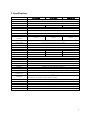
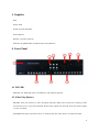
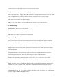
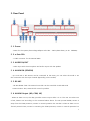
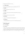
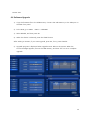
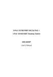
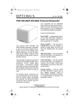
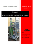
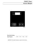
User’s Manual A Digital Hard Disk Recorder 1. Precautions for Safety Class A Device (Business Broadcasting Communication Device) The seller and the user should remember this device is certified for Class A Electromagnetic Wave, and this device is intended to be used in other places than home. The manufacturer does not take any responsibility for mental and physical damage and loss caused by the malfunction or failure of the DVR. This document is to prevent personal, material and property damage and other accidents. So, follow instructions in this document. Warning – If you don’t follow instructions, this can result in injury or death. - Do not disassemble, repair or modify the product arbitrarily. (A fire, electric shock or injury can occur. If the product needs repair, contact the service center.) - Do not damage, modify or bend the power plug. (A fire or electric shock can occur.) - Do not insert metal or flammable materials into the vent. - Keep the product away from liquid. If liquid enters the product, a fire, electric shock or injury can occur. - If there is a smoke or odor, unplug the product immediately and contact the service center. (If you keep using the product, a fire or electric shock can occur.) - Do not plug multiple devices into one outlet. (A fire can occur due to overload.) - Do not pull the power cord or touch it with the wet hand. (A fire or electric shock can occur.) - Do not shake the power cord or do not use it for other voltage than marked. (Unstable connection can cause a fire.) - Install the product where good ventilation exists and there is no heat source. Do not cover the product with a curtain or cloth. (Internal overheating can cause a fire.) 1 Warning – If you don’t follow instructions, this can result in injury or property loss. - Do not install the product under the direct sun ray or in the narrow place. - Do not install the product where there is much humidity, dust or soot. (The vent can be clogged to cause malfunction, damage or fire.) - Keep the product in the horizontal position. Do not place the container with liquid on the product. (If liquid enters the product, a fire can occur.) - Be careful when you transporting the product. (If the product falls, this may cause an injury.) - Use authenticated accessories only. - If the product has a problem, contact the seller and follow instructions. If you disassemble the product arbitrarily, repair cannot be warranted. - Use specified batteries only. (Battery damage or leakage can cause a fire.) - Do not install the product at extremely high temperatures (40℃ or higher) or low temperatures (5℃ or lower). - Hold the power plug body to disconnect the cable from the product. - Replace batteries correctly or an explosion can occur. Use batteries only with the same type and specification. Warning – If you don’t follow instructions, malfunction or data loss can occur. - Since its main purpose is to record surveillance video footage, the product is design to maintain continuous operation. - If you switch off power or unplug the product, malfunction or data loss can occur. Warning – If you don’t follow instructions, data loss can occur. - Since this product uses the HDD continuously, use the new HDD if possible. - Back up important data. - We are not responsible for data loss caused by the bad HDD. 2 2. Specifications Model Image System Multi-tasking Video In Signal Video Channel Video Output Video Compression UDR-904H UDR-908H UDR-916H HD-SDI:1080p / 720p Auto detection Quadplex HD–SDI: SMPTE 292M 4CH BNC 12CH BNC 16CH BNC HDMI(Main) , VGA(Sub), HDMI SPOT(8ch, 16ch) H.264 Display Resolution 1920Ⅹ1080p, 1920Ⅹ1080i, 1440Ⅹ900, 1280Ⅹ720p Recording Quality Max Display Speed Max Recording Speed ( 1080P) Time Laps Recording Interval (fps) Recording Mode Playback Search Playback Speed Slow Motion Sensor Input Alarm Output (Relay) Audio In/Out Network 3G Private Zone Motion Detection Hard Disk Hard Status Backup PTZ Control Serial Port 4 Levels (Low, Normal, High, Highest) Real-Time 120FPS 240FPS 240FPS 1,2,3,4,5,6,7.5,10,15,30 (NTSC/720P/1080P, 10 Steps ), 1,2,3,4,5,6,7.5,10,12.5,25 (PAL, 10 Steps) Schedule, Event (Alarm, Motion, Video loss Detection), Manual Calendar, Event (Alarm, Motion, Video loss Detection) x1, x2, x4, x8, x16 (Forward, Backward) x1/2, x1/4, x1/8 (Forward, Backward) 4 (NO/NC Selectable) 8 (NO/NC Selectable) 1 (NO/NC) , 1 TTL 2 (NO/NC) , 1 TTL 16 (NO/NC Selectable) 4 (NO/NC) , 1 TTL IN: 4ch , OUT: 1ch IN: 8ch , OUT: 1ch IN: 16ch , OUT: 1ch 10/100/1000 Base-T (Static, DHCP, E-mail), DDNS iPhone, iPad, android 20x15 22x15, 5 Level Sensitivity 5EA ,E-SATA 1 PORT SMART Function ( Hard status ) USB(Ver2.0), DVD-RW(Option), Network RS-485 RS-232(Console, Reserved) System Log DVR System Started, DVR System Shutdown, Recording Start, Recording Stop, Logout, ETC.. Language ENGLISH,CHINESE,CZECH,FRENCH,GERMAN,ITALIAN,JAPANESE,KOREAN,PORTUGUE SE,RUSSIAN, SLOVAKIA,SPANISH,TAIWAN,TURKEY S/W Upgrade Password Function Power Source Dimension Operating Temperature Weight Network, USB Memory Stick Power OFF, MENU, Record OFF, Key Lock Free Voltage Adaptor AC 100V ~ 240V ( 50Hz-60Hz ) / 4–2 A 438(W) X 440(D) X 88(H) 5℃ ~ 40℃ 10Kg (without HDD) - Above specifications can be changed for performance improvement without notice. 3 3. Supplies - DVR - Power cable - Screws for DVR assembly - User’s Manual - Remote Controller (Option) - Software CD (RAMS PRO, Uniplayer PRO, FULL_Manual ) 4. Front Panel 4.1 DVD-RW - DVD-RW: The DVD-RW drive is installed for easy backup (Option). 4.2 Video Play Buttons - RECORD: Press this button to start recording manually aside from continuous recording. Press this button once to record all channels where video signals are received. Press this button again to stop recording. - R.PLAY(Reverse Play): Press this button to reverse-play the video while it is played forward. 4 Use this button to slow down control in the PTZ control mode. - PAUSE: Press this button to pause video playing. - PLAY: Press this button to play the video according to the predefined channel, start file, audio play configuration. Also, while the video is paused, press this button to play it again. - EXIT: Press this button to stop video playing. - MENU: In the video playing or live mode, press this button to see various menus. 4.3 LED Display - POWER: When power is on, it turns green. - REC: When the video is being recorded, it blinks red. - NET: When the network is connected, it blinks green. 4.4 Function Buttons - LOCK: This button is to prevent the unauthorized user from modifying the system. Press this button to lock the DVR. In the lock mode, if you press any key, the password window will pop up. Enter the password to unlock the system. - FRZ (Freeze): In the live mode, press this button to freeze the video. Press this button again to unfreeze the video. - PTZ (Pan/Tilt/Zoom): In the live mode, press this button to enter the PTZ mode, and then control Pan/Tilt/Zoom/Focus. Press this button again to return to the live mode. - ZOOM: In the live mode, press this button to zoom in or out a certain part of the video. - SEARCH: Press this button to search videos stored on the HDD. - MULTI: Press this button to decide the display mode of the 4CH DVR. Whenever this button is pressed in the live or playback mode, the screen is switched between one-display and fourdisplay. - SEQ(SEQUENCE): In the live with one channel selected, press this button to view channels according to the CAMERA_SEQUENCE value. 5 4.5 Numeric Buttons - Press these buttons to select a channel, enter the password or the network IP in the live or playback mode. 4.6 Direction Buttons - UP: Press this button to move the cursor upward. This button raises the camera in the PTZ mode and switches channels in the playback mode. - DOWN: Press this button to move the cursor downward. This button lowers the camera in the PTZ mode and switches channels in the playback mode. - LEFT: Press this button to change the setting in the menu. This button turns the camera to the left in the PTZ mode and slows play speed in the playback mode. - RIGHT: Press this button to change the setting in the menu. This button turns the camera to the right in the PTZ mode and accelerates play speed in the playback mode. - OK: Press this button to apply the selected item. 4.7 IR Reception Terminal - This terminal receives IR data from the remote controller. 4.8 Jog/Shuttle -JOG: Use this button to view stored images one by one in the forward or reverse direction. -SHUTTLE: Use this button to fast-forward or reverse the video. 4.9 USB Port (2EA) - The USB port is used to back up videos or captured still images on the HDD. Also, the USB mouse enables easy DVR operation. 6 5. Rear Panel 5. 1. Power - Power for the system (Free Voltage Adaptor AC 100V ~ 240V (50Hz-60Hz) / 4-2A 200Watt) 5. 2. e-Sata 1EA - e-STAT connector for the external HDD 5. 3. AUDIO IN/OUT - Audio input with the microphone and audio output with the speaker 5. 4. ALARM IN (SENSOR) - Up to 16 NO or NC sensors can be connected. In the menu, you can select the mode or set the connection with the input channel (depending on the model). 5. 5. RS-485 - RS-485 SERIAL TYPE: The external controller can be controlled via RS-485 serial communication. Also, external PTZ control is possible. 5. 6. ALARM Output (NO, COM, NC) - When an alarm occurs, the relay provides contact output while it is on. The user can select one of NO, COM or NC according to the connected alarm device. The NO (normal OPEN) contact is away from the COM (common) contact in normal operation but touches it when an alarm occurs. The NC (normal Close) contact is contacting the COM (common) contact in normal operation but 7 becomes away from it when an alarm occurs. 5. 7. VIDEO IN(HD) - IN: Camera input terminal. The number of terminals differs by the model. 5. 8. SPOT - The general SPOT terminal can be used for output. 5. 9. HDMI - The HDMI port can be used to output main and SPOT signals on the monitor. 5. 10. VGA - The VGA terminal can be used for monitor output. 5. 11. RS-232 - Control can be done via RS-232 serial communication. 5. 12. Ethernet - The (10/100/1000 Mbps) RJ-45 connector can be used for Internet connection. 6. Basic Operation 6.1. Power ON/OFF 6.1.1 Power ON - When you plug in the product, the POWER LED turns green to indicate power is supplied to the DVR stably. According to HDD capacity, there can be a time difference in booting. While booting is going on, the progress bar at the bottom indicates booting status. When booting is complete, OSD (On Screen Display) is displayed. Then, the user can operate the DVR at his/her discretion. 8 6.1.2 Power OFF - Press SHUTDOWN in the system menu to turn off the DVR. When the password window appears, enter the user password (default: 111111) to shut down the DVR. After the shutdown message, remove the adapter cable from the rear panel. 6.1.3 Date and Time Setting - Enter the date and time to the DVR system. Then, go to Date/Time and press OK to apply entered date and time. 6.1.4 ID and Password Setting - Set the user ID and password for the DVR system. 6.1.5 Network Setting - Select the network type setting in the menu. STATIC, DHCP and DDNS are supported. 6.2 Recording 6.2.1 Recording Setting - Go to Recording Setting in the menu to set details. The resolution is automatically decided according to the camera input resolution. Supported resolutions are 1280Ⅹ720P, 1920Ⅹ1080i, and 1920Ⅹ 1080P. *Note: Select the same resolution for the HD camera, and then select the input for each channel. (EX) Scenario 1: 720p for all HD channels; Scenario 2: 1080p for all channels; Scenario 3: 1080i for all channels; Scenario 4: AUTO) Also, you can decide which audio is connected to which video channel and set recording quality for each channel. Four recording qualities are available: NORMAL, LOW, HIGH, and HIGHEST. You can set different or the same quality for each channel. Lastly, you can select recording conditions. For more information, “see 3.2 Recording Setting Menu in the Full Manual.” 6.2.2 Recording Condition Setting - You can record according to recording settings - REC1, REC2, and REC3. For more information, 9 “see 3.2 Recording Setting Menu in the Full Manual.” 6.3 Play 6.3.1 Play with the PLAY Button - Press the PLAY button to play the video according to the channel, play start point and audio setting selected in the menu. 6.3.2 Audio Play - To play the audio-linked file, select the channel, and then click on the RIGHT button. Then, the audio menu appears. Turn on audio and click on PLAY to play the audio. Or, in the front panel of the DVR, press OK, select the channel, and press OK again to display the audio menu. Turn on audio and click on PLAY to play the audio. 6.4 Search The DVR has four search modes. 6.4.1 Search Modes - Quick Search: Enter YYYY/MM/DD for quick search. - Calendar Search: The calendar search environment is provided to enable the user to view recording data at a glance. - Event Search: The recording data list is displayed for ALRAM, MOTION, VIDEO LOSS events. - OVERLAPPED LIST: The list of data overlapped overtime. 6.4.2 How to Search - Quick Search: Press the Search button to show four search modes. Select TIME, enter YYYY/MM/DD, and then press OK to play channels of the selected time simultaneously. - Calendar Search: Press the Search button to show four search modes. Select CALENDAR to display the YYYY/MM/DD window. Select the year, month, date, hour and minute step by step to play channels of the selected time simultaneously. - Event Search: Press the Search button to show four search modes. Select EVENT, turn on/off 10 search conditions, and then select the LOG list to show the event list. Then, select the desired event list to play channels simultaneously. - OVERLAPPED LIST: Press the Search button to show four search modes. Select OVERLAPPED LIST to display the list of data overlapped overtime. Then, select the desired list to play channels simultaneously. 6.5 Backup 6.5.1 DVD-RW (Option) - Insert the DVD-ROM to the DVD-RW drive, press the Menu button, and then use the backup menu to back up videos on HDD for a certain period of time to the DVD-ROM. - In the Backup menu, select DVD/RW as a target, select the backup time/backup file name/backup channel, and then select WRITE to start backup. (If ESTIMATE is selected, the selected backup volume is calculated.) - Since our Uniplayer PRO is included in the backup CD/DVD, videos can be played in other PCs. - Backup files can be played by Uniplayer PRO on the CD supplied with the DVR. 6.5.2 USB Memory - Files can be backed up to the USB memory connected to the USB port. Connect the USB memory and use the system setting and backup menu to back up videos on HDD for a certain period of time to the USB memory. - Connect the USB memory, select USB as a target, select the backup time/backup file name/backup channel, and then select WRITE to start backup. (If ESTIMATE is selected, the selected backup volume is calculated.) - Since our Uniplayer PRO is included in the backup CD/DVD, videos can be played in other PCs. - Backup files can be played by Uniplayer PRO on the CD supplied with the DVR. 6.5.3 Network - Video and audio files on the DVR HDD can be backed up to user ’s PC via the network from the 11 remote area. 6.6 Software Upgrade 1) Copy the firmware file to the USB memory. Connect the USB memory to the USB port on the DVR front panel. 2) In the DVR, go to Menu > INFO > UPGRADE. 3) Select DEVICE, and then press OK. 4) When the device is selected, press the START button. After waiting a moment, if you want upgrade, press OK, if not, press CANCEL. 5) Upgrade progress is displayed when upgrade starts. Reboot the system. When the success message appears, remove the USB memory, and then click on OK to complete upgrade. 12 6.7 Client Program 6.7.1 RAMS PRO - This program allows live video monitoring through remote access to the DVR over the network, search/play of data on the DVR, and their backup to the client. - DVR software upgrade - Run RAMS PRO and press the button to display the DVR list window. In Connect, create the group, enter the name, address, port, ID, and password of the DVR to be accessed, and press ADD to save them. - The default value is: “PORT: 7000, ID: ADMIN, PASSWORD: 111111” 6.7.2 Uniplayer PRO - This program allows play of files recorded, captured or backed up by RAMS PRO. 6.7.3 Mobile Viewer - With the PDA or smartphone with access to the wireless Internet, DVR status and videos can be monitored in real time.. - i-RAMS pro: real-time DVR status and video monitoring program for the i-Phone - a-RAMS pro: real-time DVR status and video monitoring program for the Android phone 7 Default ID/Password - By default, the DVR has ADMIN1, ADMIN2, and User1~6. - By default, the client can have ADMIN1, ADMIN2, and User1~6. - When the DVR is used for the first time, following password is set to ADMIN. For other users, their password should be set. - ID: ADMIN Password: 111111 13 8. Warranty Warranty Thank you for buying our product. THEALLMEDIBIO abides by the Regulation on Compensation for Customer Damage. 1. This product has passed thorough quality control and precision inspection. 1. This product is warranted for one year after its delivery. - If a fault occurs while the product is used normally, it can be repaired free in our service center or dealer shop. 3. However, for followings, service fees are charged even if the warrant period is not over. - Malfunction and failure that occur after the warranty period - Malfunction and failure caused by the user’s negligence - Failure caused by natural disaster - Failure caused as instructions or precautions in the manual are not followed - Failure caused as specified power is not used - Cleaning or accessories - Failure caused as the user repairs and modifies the product arbitrarily 4. Product Information Model No. Serial No. Date of Purchase Seller Customer Name Address THEALLMEDIBIO. CO., LTD. 14