1
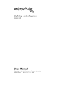
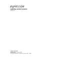
USER MANUAL
Contents
SPECIFICATIONS ........................................................................................................ 1
CONTROL REFERENCE .... ........................................................................................ 2
FRONTPANEL ............................................ . .... ................................................ 2
BACKPANEL.. .................................................................................................. 4
MODE SELECTION.. ................................................................................................... .6
RECORD.. ..................... ... ................................................................................... .6
PLAY.. ................................................................................................................
.6
SETUP.............................................................................................................................
7
SETUP PROCEDURES.. .................................................................................. 7
DESK LAMP INTENSITY .............................................................................. 7
ANALOGUE OUTPUT
T POLARITY.. ........................................................... 7
MEMORY ALLOCATION ............................................................................. .8
SOFT-PATCH DIMMERS.. ............................................................................. 8
AUTO-INCREMENT ..................................................................................... .8
FLASHINGCDRSOR ..................................................................................... 8
IN / OUT-FADE TIMES................................................................................. 8
MANUAL CONTROLS .............................................................................................. 9
PRESETS ............................................................................................................
9
ADD/KILL BUTTONS.. .................................................................................. 9
DEAD BLACKOUT (DBO). ............................................................................. 9
GRAND MASTER ........................................................................................... 9
SCENES.. ........................................................................................................................
10
RECORDING SCENES .................................................................................... 10
EDITING SCENES.. ......................................................................................... . 1 0
BLIND RECORDING.. ....................................................... . ............................. 10
PLAYING BACK SCENES.. ............................................................................ 11
SWAPPING SCENE BANKS.. ...................................................................... 11
CHASES. ........................................................................................................................
12
RECORDING CHASES .................................................................................. .12
PLAYING BACK CHASES.. ........................................................................... 13
EDITING CHASE STEPS ............................................................................... .13
OUTPUT HOLD ............................................................................................................
15
CROSSFADE .................................................................................................................
15
SOFTPATCH.. ...............................................................................................................
15
...............................................................................................................................
16
MIDI & DESK LINKING.. ........................................................................................... 17
NOT USING MIDI or DESK LINKING ....................................................... 17
LINKING TWO INSTINCT CONSOLES .................................................... 17
MIDI RECEIVE.................................................................................................. 17
Technical Notes for MIDI.. ............................................................................ .18
M-CARD ........................................................................................................................
19
CLEARING MEMORY ................................................................................................ 20
Appendix A INSTALLATION.. ............................................................................... 21
Appendix B MAINTENANCE.. .............................................................................. .22
Appendix C TECHNICAL INFORMATION.. ...................................................... 23
Jands Electronics Pty Ltd
578 Primes Highway
St Peters 2044 Australia
Phone (02) 516 3622
Fax
(02) 517 1045
JANDS INSTINCT Lighting Control Console
SPECIFICATIONS
Channels
cenes
hasers
OUTPUTS
Analog
Digital
CONNECTORS
Analog Out
48,60or72
864 Maximum
36 Maximum (864 Steps)
0 to 10 volts DC
Positive or Negative polarity
RS485 standard
USITT DMX-512 protocol
2 x Bumdy 48 Pin Female or
2-3 x Socapex 337 Female
1 x Cannon 5 Pin Female
Digital Out
Audio Trigger 3-pin Female AXR
MIDI In/out 2 x 5-pin Female Din
DESK LAMP
12v current limited
supply
2 x Littlelite 12G Hi
Lamp Type
2 x Cannon 3 Pin female
Connector
‘OWER
Requirements 240 or 110 volts
45 Watts (85 Watts w / analog outputs), 50 - 60 Hz
C o n n e c t o r IEC
2 amp 3AG
Mains Fuse
DIMENSIONS (1 x d x h)
1200mm x 530mm x 12Omm.
48 Channel
1460mm x 530mm x 12Ornm.
60 Channel
1720mm x 530mm x 12Omm.
72 Channel
WEIGHT
48 Channel
20 kg
60 Channel 22kg
72 Channel 24kg
1.2mm steel front panel locked into aluminium
Construction:
extrusions and internal bracing panels to form a
lightweight rigid chassis. Customwood end pieces.
The front panel is one-piece reverse-screened Lexan to
Finish:
provide a durable tough finish. Switch caps are black
with white hot-stamped lettering to indicate channel
number or function.
The base can be removed after releasing the screw:
Access:
holding it to the chassis. Two separate panels may then
be hinged down to provide access to the Power Supply
and all printed circuit boards. As high voltages arc
present in the power supply, and there are no userserviceable parts inside the console, the base should
not be removed by the user. Servicing should be
strictly left to qualified personnel or service agents.
1
User Manual V 2.2
JANDS INSTINCT Lighting Control ,Console
.CONTROL REFERENCE
FRONTPANEL
1
Preset - There are two rows of preset faders which can be used to
control the output of individual channels.
2
Preset Master - These two sliders control the maximum level of their
respective sets of Preset sliders. Under control of Grand Master.
P1 Button - Add / Kill buttons for Preset 1.
P2 Button - Add / Kill buttons for Preset 2.
Scene Masters.- Each of these 24 sliders may be used to fade a prerecorded group of channels (a Scene) up or down. Under control of
Scene Master.
6
Scenes Grand Master - Controls the maximum level of the 24 Scene
Master sliders. Under control of Grand Master.
7
Add/Kill Button - These non-latching buttons are used to flash a
Channel, Preset or Scene to the level set by the Add/Kill Master slider.
When set to ADD, the selected output is added to the existing output
of the console. When set to KILL, the selected output will flash to the
level set by the Add/Kill master while blacking out or killing all other
outputs.
8
Add/Kill Master - Controls the maximum level of the Add/Kill
function.
9
Add/Kill Select Button - Swaps the Add/Kill buttons between the Add
and Kill modes.
10 Hold Button - Pressing Hold places the existing output of the console
onto the Hold fader. A second press of Hold clears the hold memory.
11 Output Hold Fader - This slider is used to control the level of the
information stored in the Hold memory. Under control of Grand
Master.
12 Chaser A Master - Controls the maximum level of Chase A sequences.
Under control of the Grand Master.
13 Chaser B Master - Controls the maximum level of Chase B sequences.
Under control of the Grand Master.
2
User Manual V 2.2
I
14
Ch A Button - Chaser A One-Shot button. When pressed, the button
will trigger Chaser A to run its programmed sequence once and then
stop. The Chase Rate will be set by the Chaser A Rate slider. Note that
this button acts in the same way as an Add/Kill button, when pressed
the level of the chase will be controlled by the Add/Kill Master and in
the Kill mode all other outputs will be blacked out.
15 Ch B Button - Chaser B One-Shot button. When pressed, the button
will trigger Chaser B to run its programmed sequence once and then
stop. The Chase Rate will be set by the Chaser B Rate slider.
16 Grand Master - Controls the maximum level of all level Masters
except the Add/Kill Master.
17 DBO Button- This Latching button (push on-push off) will disable all
console output.
18 Sample Button - Pressing this button stores the current desk output in
memory as a Crossfade source.
19 Cross Fade Button - Initiates the Crossfade which fades the sampled
output to the selected scene output.
20 Crossfade Rate Slider - This slider is used to manually override the
crossfade rate. When in the centre position the fade-in and fadeout
rates proceed at the rates set in the setup menu.
21 Chaser Rate - This slider is used to control the speed of the Chaser. The
Chaser will stop at minimum rate and can then be single-stepped by
placing the cursor under “step”and using the Up/Down buttons.
22 Go/Cue Button - Start/Stop control for the Chaser. When CUEd, the
Chaser rate may be monitored and adjusted before pressing GO. This
button will also cancel a one-shot chase.
23 Fwd/Rev Button - Toggles Chaser operation between Forward,
Reverse and Bounce.
24 Display - The 48 character, backlit, Liquid Crystal Display (LCD) displays
menus for Scene, Chase A, Chase B, Setup, and Softpatch as well as
help messages.
25 Cursor Keys (up, down, left, right arrows) - Moves the cursor around
the various items on the menus displayed on the LCD
26 Up Button - When pressed, will increment the number or function
under the cursor in the Display. When held down, it will behave as a
“fast-forward” button. When both Up and Down are pressed together,
the number in the Display will reset to its minimum value.
3
User Manual V 2.2
27 Down Button - When pressed, will decrement the number under the
cursor in Display. When held down, it wiII behave as a “fast- rewind”
button.
28 Full - This button allows values displayed in the LCD to be quickly set
to their maximum value. It provides a convenient alternative to
holding the up button pressed.
29 Scene - Pressing this button accesses the Scene Menu which is
displayed on the LCD. .
30 Chase A - Enables the Operator to Record, Edit or Play Chase
sequences.
31 Chase B - Enables the Operator to Record, Edit or Play Chase sequences.
32 Setup - Enables the Operator to set various INSTINCT parameters to
cater for a particular job and personal preferences.
33 Softpatch - Enables the operator to program patching information.
Three separate patches may be programmed and stored in the Instinct.
34 Midi - Pressing this button accesses the Midi Menu which is displayed
on the LCD.
35 Record - If pressed in the Chase or Scene menu the current desk
output will be recorded. If pressed in the Edit Channel mode the
contents of the edit buffer will be recorded. Record is also used to store
a softpatch that has been altered.
36 Help - To display help on the function of a button press “Help” then
the button you need help with. If you need to know about something
on the LCD place the cursor under it and press help twice. Help
messages scroll automatically or can be accelerated using the down
arrow key.
37 Edit Chan - Allows editing of Channel levels in Scenes and Chases.
Only available when SCENE, CHASE A or CHASE B are selected first.
BACKPANEL
38 Mains Control - Inlet socket, 2 amp fuse and desk ON/OFF switch.
39 Mode Select Switch - A key-switch to alternate the Operating Mode
between Play and Record.
40 Chaser Trigger - Will accept audio signals from microphone to line
level. Chaser steps are then triggered from pulses derived from this
input.
4
User Manual V 2.2
41 Digital Output - 5 pin AXRconnector with digital multiplexed output.
Conforms to USITT. DMX-512 Digital Protocol.
42 Midi In/Out - Standard MIDI connection for communication with
MIDI controller. Also used for, linking two, Instinct consoles.
43 Interface RS 232 - Connection to allow communication between the
console and a Personal Computer. This facilitates storing of INSTINCT
information on floppy or hard disks, or programming on computer
and then down-loading to the INSTlNCT.
44 Link - -This connector is not currently used.
45 Analogue Output (optional) - Burndy 48 pin or Socapex 37 pin
connectors which provide discrete analogue outputs (0 to +/- 10 volts).
46 M-Card Slot - Connection for an optional Memory Card. Used to
backup information from the console..
5
User Manual V 2.2
JANDS INSTINCT Lighting Control Consolc
‘,
MODE SELECTION
The INSTlNCT has two Operating Modes: PLAY and RECORD. It is
possible to alternate between these two modes by use of the keyswitch
which is located on the rear panel of the console.
RECORD
In the Record mode Scene, Chase, Setup and Softpatch recording is
possible. In this mode all functions are available to the Operator. When in
the record mode the display shows an r in the top left hand comer.
PLAY
The Play mode is indicated by a small p in the top left hand comer of the
display. When the console is switched to play the operator is prevented
from changing any recorded information. In the play mode it is not
possible to:
n re-record or edit scenes
n alter the chases in any way
n alter anything in the setup menu with the exception of desk lamp
intensity and crossfade times.
n change the selected softpatch
The play mode can be used to lock out dimmers by softpatching their level
to zero.
6
User Manual V 2.2
JANDS INSTINCT
Lighting Control Console
When the Instinct is powered up for the first time the operator may wish
to change some of the default factory settings which influence the way the
console operates. However it is not necessary to change any of these
settings in order to use the desk and many users will find the default
setting suitable for their immediate use.
The setup options available and their default settings are as follows:
m Control desk-lamp intensity.
100%
W Analogue output polarity
Negative
25 Banks (600 Scenes)
m Available. Scenes Banks
12 Chases
W Available Chases.
200
m Number of dimmers to Softpatch
w Auto-Increment Scenes & Chase Steps On
1 Minute
n Crossfade In-fade and Out-fade times
SETUP PROCEDURES
To enter the Setup mode, press the SETLJP Function button. The Setup
menu will appear on the LCD Disolav, as illustrated below:
Desk Lamp Level:Full
Total Banks: 25
Since the Display can only show 2 lines at a time it is necessary to use the
cursor 1‘ & 3. kevs to see the rest of the menu. Pressing the J key will reveal
the rest of the menu as follows:.
Total Chases: 12
I
Once the required option has been located the Up or Down Keys are used
to change the setting. Note that using the cursor ?’& J keys normally keeps
the cursor under the setting to be changed. However when setting In fade
or Out Fade times it may be necessary to use the t & 4 keys to locate the
cursor under either the minutes or seconds setting.
DESK LAMP INTENSITY
The desk lamp intensity may be varied from zero to full (100) to allow the
Operator to choose an optimum intensity for different ambient lighting
conditions.
ANALOGUE OUTPUT POLARITY
The polarity of the Analogue Outputs may be set to either Positive (+) or
Negative (-). This is to cater for certain dimmers that only accept single-
JANDS INSTINCT
Lighting Control Console
MEMORY ALLOCATION
There is enough memory in the Instinct to store a total of 37 scene banks
(each bank contains 24 scenes) and chases. A scene-bank is the same size as
a chase so increasing the number of chases by one will reduce the number
of scene banks by one and vice versa. To alter the scene bank to chase ratio:
0 Ensure that the Mode Select switch on the back panel is set to the
Record Operating Mode.
Q Press Setup and place the cursor under Total Banks (or Total Chases)
0
Use the Up Down Full buttons to alter the number.
The ratio of scenes to chases can be set from 1 scene bank and 36 chases to
36 scene banks and 1 chase.
Each scene bank consists of 24 scenes and each Chase is made up of of 24
steps.
SOFT-PATCH DIMMERS
The Digital output can be Soft-Patched before leaving the INSTINCT. This
eliminates messy and tedious dimmer patch wiring at the dimmer racks.
In the Setup mode it is possible to set the number of dimmers to be
patched from 72 to a maximum of 200. However it does not matter if there
are less dimmers used than this number indicates.
AUTO-INCREMENT
When Auto-increment is on, every time you record a Scene or Chaser
Step - the scene number or chase step number in the Display automatically
advances by one.
FLASHING CURSOR
Allows different cursor shapes to be used
IN / OUT-FADE TIMES
This allows the Operator to set separate In-fade and Outfade times. This is
the time taken to crossfade with the Crossfade Rate slider in the middle.
Enter a time from 1 second to 99 minutes 59 seconds.
8
User Manual V 2.2
MANUAL CONTROLS
PRESETS
The PRESETS are the sliders that manually control individual channel
output on the console. On the INSTINCT there are two rows of sliders
which allow the operator to ‘preset’different lighting looks and to fade
between them. Each row of presets has a PRESET MASTER which
determines the overall output level for all the sliders of that row. eg. if
slider 12 is at 80% and it’s Master is at 50% then the output from Channel
12 will be at 40%.
ADD/KILL BUTTONS
Pressing a channel Add/Kill buttons causes the individual Channel
outputs to flash instantly to the level set by the Add/Kill Master slider.
Pressing a scene Add/Kill buttons causes the Scene output to flash
instantly to the level set by the Add/Kill Master. The Add/Kill Master is
not controlled by the Grand Master slider. It is the only level fader that is
independent of the Grand Master.
If the Add/Kill Select in the Mastering section is set to ADD, then pressing
an Add/Kill button will flash that Channel or Scene to the level of the
Add/Kill master, and Add it to the console’s current output.
If the Add/Kill Select is set to KILL, Then pressing an Add/Kill button will
flash that Channel or Scene to the level of the Add/Kill master (as before),
but it will blackout or kill all other console output.
DEAD BLACKOUT (DBO)
The DBO button is used to instantly kill all console output. It is a push-on,
push-off button, and it’s LED indicates when the DBO is active
GRAND MASTER
This slider determines the overall output level for all controls on the
Instinct except the Add/Kill buttons.
9
User Manual V 2.2
JANDS INSTINCT Lighting Control Console
RECORDING SCENES
Ensure that the Mode Select switch on the back panel is set to Record.
Press the Scene button and the display will show the Scene menu as
illustrated below:
1 Scene: 1
Use the cursor buttons to move the cursor within the Display, and the
Up/Down buttons to change the following settings:
Set the Bank number (1 to 36 - depending on the setup configuration).
Set the desired Scene Number (from 1 to 24).
Set up the desired outputs for this Scene using the Presets or Scene
Masters and press the RECORD button. The Display will show
‘RECORDED” on the second line. If the Auto-increment is active (see
section 4.5) the Display will update to the next Scene. Otherwise, press
Up to set the Display to Scene 2.
Set up outputs for the second and subsequent scenes and Record them
as above.
Remember that the Up and Down buttons will repeat if kept pressed. Also
the Display can be made to reset to one by pressing Up and Down together.
EDITING SCENES
If the level of a particular Channel within a Scene needs to be altered
(edited),
Q Ensure that the Mode Select switch on the back panel is set to Record.
Q Press the Scene Function button and then the Edit Chan Function
button.
0 Using the Cursor and Up/Down buttons, select the Bank and Scene
numbers.
@ Select the Channel number and new level (0 to full)
0 Press the Record button.
If the altered Scene is not rerecorded, the changes will be ignored. In this
way scenes can be altered on stage without necessarily being permanently
stored.
BLIND RECORDING
If the scene master for the scene being edited is up (the scene is on stage)
then the edit will be live and the operator will see the changes being made.
If the scene master is at zero then it will be a blind edit.
10
User Manual V 2.2
JANDS INSTINCT Lighting Control Console
PLAYING BACK SCENES
To play back a Scene, press the Scene function button. The LCD display
will show “Bank xx”. Select the appropriate bank with the Up or Down
buttons, and move the desired Scene Master slider, or press it’s Add/Kill
button. The Scenes Master in the Mastering section controls the
maximum level of the Scene Masters.
It is possible to operate up to a full Bank of 24 Scenes simultaneously.
SWAPPING SCENE BANKS
It may be desirable to simultaneously use Scenes from different Banks, or
to manually cross-fade from a Scene on one Bank to a Scene on another
bank. This may be acheived using the Output Hold facility.
Q Select a Scene and set it to the desired level.
8 Press the Hold button. The Hold LED will turn on to show that the
Hold facility is in use. Advance the Hold fader to maximum.The
Scene Master slider can now be returned to zero, because the Hold
slider now has control of the Scene.
0 Leaving the Hold slider at maximum, select the Bank for the other
Scene. The two Scenes may now be used together, or cross-faded by
pushing up the new Scene Master slider to full while simultaneously
pulling back the Hold slider to zero.
An alternative method for scene bank swapping is to have a common
scene recorded in both banks. The operator may have the last scene in each
bank the same as the first scene in the proceeding bank.
11
User Manual V 2.2
JANDS INSTINCT Lighting Control C o n s o l e
RECORDING CHASES
The Chaser is used to automatically sequence through a pre-recorded
series of “scenes” called STEPS. The operator can control the level, speed,
and direction of the Chase sequence. Programming a Chase is similiar to
the procedure described previously for scenes:
Q Ensure that the Mode Select switch on the back panel is set to Record.
Q Select either the Chaser A or Chaser B function button and the display
will show. the chase (A or B)menu as illustrated below:
Chase A:. 1 Step: 1
Lenqth: 24
Since the Display can only show 2 lines at a time it is necessary to use the
cursor T & 4 kevs to see the rest of the menu. Pressing the J key will reveal
the rest of the menu as follows:.
1 Audio: Off Chase B OnlyI
Chasemode:Sequential
Attack Time:
Off
Decay Time:
Off
END
Next Chase:
END
Prior Chase:
Max Rate:
984 BPM
Use the cursor buttons to scroll the Display, and the Up/Down buttons to
_
change the following settings:
Set the Chase number (1 to 36 - depending on the setup configuration)
and Step number .
Set the desired chase length from 1 to 24 steps.
Chaser B can be set to trigger from an audio input if required.
Set Sequential or Random pattern.
Setting attack time on lets the outputs fade up to full level over half
the step time.
Setting decay time on lets the outputs fade down to zero level over
half the step time.
Next Chase can be set to join the end of the current chase to the
beginning of another chase
Prior Chase can be set to join the beginning of the current chase to the
end of another chase
Set the maximum chase rate in beats per minute (BPM). The default
(and maximum) setting is 984 BPM. This will be the chase speed with
the rate fader set to 10. The fader can then be used to slow down the
speed.
Set up the desired outputs for the first Step using the Presets or Scene
Masters and press the RECORD button. The Display will return to the
first two lines and show “RECORDED” on the second line. If the Autoincrement is active (see section 4.5) the Display will update to Step 2.
Otherwise, press Up to set the Display to Step 2.
12
User Manual V 2.2
JANDS INSTINCT lighting Control Console
@ Set up outputs for the second and subsequent steps and Record them
as above.
Remember that the Up and Down buttons will repeat if kept pressed. Also
the Display can be made to reset to, one by pressing Up and Down together.
PLAYING BACK CHASES
T o play a Chase sequence, press the Chase A or Chase B Function buttons
and select the Chase number with the Up or Down buttons. Any Chase
sequence can be assigned to either Chaser A or Chaser B - they both access
the same memory. Select the speed of the Chaser with the CHASER RATE
slider. The flashing red LED in the GO/CUE button indicates the Chaser
rate.
When the Chaser rate is correct, pressing the GO/CUE button will start the
Chase sequence. The Chaser Master controls the output level of the
Chaser. Pressing the GO/CUE button a second time will stop (Cue) the
Chaser.
If the Chaser is active, the Display will show the current Chaser Step
number. If the Rate slider is then set to zero, the Up and Down buttons
may be used to single-step the Chaser.
The direction of the Chaser may be changed with the FWD/REV button.
When the green FORWARD LED is on, the Chase will run from step 1 to
the highest number step. When the red REVERSE LED is on, the Chase
will run from the highest number step to Step 1. When both LEDs are on,
the Chase will run from Step 1 to the highest number step and back to
Stepl, and continue in this manner. This is called the BOUNCE mode.
Pressing the FWD/REV button toggles it to the next mode.
The Chasers also have a ONE-SHOT function. This is triggered by the CH
A or CH B buttons in the Mastering section. When triggered, the Chase
will sequence from Step 1 to the set Length and then stop. The Chase Rate
slider determines the rate of the sequence. If the REV LED is on, the OneShot will start at the highest Step and sequence backwards to Step 1. If
Bounce is on, the One-Shot will sequence one complete forward and
backward cycle.
EDlTING CHASE STEPS
If it is discovered that a particular Step in a Chaser is incorrect it may be
edited as follows:
Select Chase A or B;
Select Chase number;
0 Select Step number;
@ Set up correct Channel outputs;
8 Press Record button.
Q
Q
13
User Manual V 2.2
JANDS INSTINCT Lighting Control Console
It is also possible to edit particular channels using the Edit Chan Function
button. First press Chase A or Chase B and then press Edit Chan. Use the
Cursor and Up/Down buttons to select the Chase and Step numbers, and
then select the Channel number and the new level. When all have been
changed, pressed the Record button to store the changes in memory.
Failure to do this will result in the changes being ignored.
Press Chase A or B;
Press Edit Chan;
Select Chase number;
Select Step number;
Select Channel;
Select new level;
Press Record button.
14
User Manual V 2.2
JANDS INSTINCT Lighting Control Console
OUTPUT HOLD
Pressing the Hold button will save the current console output onto the
Hold fader. A second press will clear the Hold memory.
Hold is useful when changing scene banks but may also be used as a third
preset or to freeze a chase step.
CROSSFADE
A crossfade facility has been included to allow a smooth and repeatable
fade-in/fade-out between two different scenes. To fade from a, current
Scene to a new Scene, press the SAMPLE button. This stores the current
console output in the Crossfade memory, the output is maintained by the
Crossfade function and the Scene controls are disabled. A new Scene may
now be selected.
When ready to fade, press the X fade button. This starts the fade between
the output as sampled and the new scene. The rate slider will override the
X fade. With the slider in the middle, the fade will proceed at normal rate.
When pushed to the top, the fade will accelerate, or when pulled to the
bottom, the fade will stop. Separate in and out fade times can be set in the
setup mode (up to 99 mins 59 secs).
SOFTPATCH
SOFTPATCH may be used to patch the INSTINCTS DMX-512 output to
dimmers using this protocol or via a demultiplexer (such as the Jands
DDX 48) to normal analogue dimmers. This eliminates the need for a
matrix or "spaghetti patch” at the dimmer racks, and allows the dimmers
to be re-patched quickly and easily during a performance. Three different
patches may be stored in memory as Patch 1, Patch 2 and Patch 3.
It is important to note that patching is done by dimmer channel. Hence
the dimmer to be patched is selected first then the desk channel to control
it is chosen. A particular desk channel may be patched to any number of
dimmers, but two or more channels cannot be patched to the same
dimmer.
To record or alter a softpatch:
0 Ensure that the Mode Select switch on the back panel is set to Record.
Q Press the Softpatch button and then display will show:
Patch No: 1
1 At:Full
0 With the Cursor under Dimmer number select the dimmer to be
patched. At this point changing the dimmer number with the
Up/Down/Full buttons allows the operator to view the existing patch
but does not alter it.
15
User Manual V 2.2
0 With the Cursor under channel number the Up/Down/Full buttons
will change the desk channel that is patched to the selected dimmer
channel.
0 With the cursor under the At level the proportional level of that
dimmer is changed using the Up/Down/Full buttons.
63 Press the Record button to save the changes.
Note: All patch changes are live, it is not possible to record one softpatch
while using another.
HELP
The help button gives two kinds of help. Firstly there is help on the
INSTINCT button functions. Secondly there is help for the messages on
the LCD. If you want to find out about a certain button, first press “Help”
then that button. I f you want to find out what a message on the LCD
means, then place the cursor under it and press “help” twice.
Help messages are generally bigger than can fit on one LCD screen. For this
reason the text will automatically scroll after a short delay to the next page.
Speedy readers can advance to the next page by pressing “down arrow”.
16
User Manual V 2.2
MIDI-& DESK LINKING
NOT USING MIDI or DESK LINKING
When not using MIDI set MIDI mode (press the MIDI button to get to it) to
off. This will prevent the MIDI-in socket from controlling the desk.
When not linking two desks together set LINK ‘mode to NORMAL.
LINKING TWO INSTINCT CONSOLES
Desk linking allows two Instincts to be connected together and have
common mastering, synchronized chases etc. Desk linking does not affect
record and edit functions. These will have to be performed on each desk
individually. The linking ensures that both desks are playing the same
thing at the same time. Also the two desks still have separate outputs.
To link a pair of desks:
0 Connect the MIDI out of one to the MIDI in of the other. Do this again
in the other direction so that both MIDI connectors on both desks are
connected to the opposite type of MIDI connector on the other desk.
Q Select the MIDI menu by pressing the MID1 button and the display will
show the following menu.
MASTER LINK Mode
1 MIDI Channel
I
Since the Display can only show 2 lines at a time it is necessary to use the
cursor ? & J keys to see the rest of the menu. Pressing the & key will reveal
the rest of the menu as follows:.
rzJzJ?J
Use the cursor buttons to scroll the Display to LINK Mode.
Q Set one desk into MASTER mode and the other into SLAVE mode.
The master desk will now control the slave in the following functions:- all 24 scene masters
- the cross fader
- the hold control
- preset and chaser masters
- the grand master
- add/kill
- chaser speed and direction
Therefore the only controls on the slave desk that need be used are record
and edit functions along with the presets themselves.
If you want to use two linked desks with a MIDI input then you will have
to remove the plug in the MIDI-in of the master desk and put the MIDI in
here. The desk link is now taking place over only one cable. The removed
cable made a kill on the slave desk cause a kill on the master desk so you
will no longer have this ability.
MIDI RECEIVE
17
User Manual V 2.2
JANDS I N S T I N C T L i g h t i n g Control Console
The MIDI input on the Instinct allows any MIDI device such as a keyboard
or a sequencer to access and control the scenes and chases on the Instinct.
Connect the MWI out on the device to MIDI in on the Instinct using a
suitable cable.
Select the MIDI menu by pressing the MIDI button and the display will
show the Midi menu as illustrated below:
I
1
NORMAL LINK Mode
1 MIDI Channel
I
I
Since the Display can only show 2 lines at a time it is necessary to use the
cursor T & & keys to see the rest of the menu. Pressing the J key will reveal
the rest of the mend as follows:.
Use the cursor buttons to scroll the Display, and the Up/Down buttons to
change the following settings:
0 Set MIDI channel to the MIDI channel your MIDI device is sending on.
(1 - 16)
@ Select MIDI mode on.
The two MIDI machines are ready to talk. C (2 octaves below middle C)
will start/stop chase A. The notes chromatically above that have the
function listed in the table below. For the scene masters the note velocity
corresponds to the scene master intensity.
Note
36
37
38
39
40
41
42-65
Function
C Chase A Start/Stop
C# Chase B Start/Stop
D Chase A One Shot
D# Chase B One Shot
E Chase A single step
F Chase B single step
F# Scene masters 1 to 24
Technical Notes for MIDI
Digital values (switches) use the convention of anon-zero velocity for
switch on and a zero velocity for switch off. For analog values (levels) the
velocity is the intensity (C-127). The Instinct MIDI interface uses only notes
and velocities to transfer data. Note off is interpreted in the same way as
note on with zero velocity. MIDI receive is in OMNI off/poly mode when
normal link mode is selected. If either slave mode or master is selected
then MIDI will be in OMNI mode On.
18
User Manual V 2.2
J a n d s INSTINCT Lighting Control Console
M-CARD
It is possible to store all the information programmed into the INSTINCT
on a compact memory card. The memory card (M-Card) may be used to
safeguard data, transport information from one Instinct to another and
expand the number of available scenes and chases. Recording or reading
an M-Card takes less than 1 second.
The procedure for using an M-Card is as follows:
Insert the M-Card, screened side up, into the rear panel connector. The
M-Card has an On/Off switch which must be in the ON position to
allow Recording.
Press the M-CARD function button
The Display will now show:
Press the ‘r (up arrow) cursor key to record information from the
Instinct to the M-Card
Press the .I, (down arrow) cursor key to record information stored in
the M-Card to the Instinct.
Depending on your choice you will be prompted as illustrated below to
confirm the action.
Write INSTINCT TO MCARD
1‘ for YES J for NO
Rz OR
O
Read MCARD
to INSTINCT
T for YES 1 for NO
8
@
Press the T (up arrow) cursor key to confirm the action
Press the .I. (down arrow) cursor key to cancel the action.
Remember that reading from an M-Card will erase all information
currently in the Instinct and replace it with information stored in the MCard.
19
User Manual V 2.2
J a n d s INSTINCT Lighting Control Console
CLEARING MEMORY
There is normally no need to clear t h e entire memory of the Instinct. This
procedure should only be used when information recorded in the console
is no longer required.
To clear the lNSTINCT memory hold down the Pl, P2, CHASE. A and
CHASE B Add buttons whilst turning the desk power on. The Display will
now show the following:
Clear the Desk?
t F o r Yes, &for NO
I
the ?’ key now allows the operator to proceed to clear areas of
memory selectively. Pressing the 1 exits this operation.
Pressing
The next screen that appears in the display allows all scene and chase
information to be erased:
Clear Chases & Scenes ?
,r For Yes, Jfor No
The next screen that appears in the display allows all softpatch
information to be erased:
Clear the SOFTPATCH ?
-r For Yes, Jfor No
next screen that appears in the display allows all setup information to
be erased. Clearing the Setup information resets the factory defaults (see
SETUP).
The
I
Clear the SETUP ???
,r For Yes, Jfor No
I
After proceeding through these screens the display returns to show scene
information.
20
User Manual V 2.2
JANDS INSTINCT Lighting Control Console
Appendix B MAINTENANCE
The INSTINCT series has been designed to withstand the rigours of
touring use. However, it may still be damaged by gross misuse. Note that
the warranty does not cover damage of this sort. Protective road-cases are
available for the INSTINCT series and are essential if the console is to
travel extensively.
Be careful not to spill liquids onto the Instinct. The lexan front panel
provides a very durable surface but a cup of coffee entering the console
through the slider cutouts will probably cause serious damage.
It is usually. quicker and cheaper to double-check connections to the
console before turning the power on, than it is to replace destroyed
components and circuit boards. If in doubt, ask someone who does know.
It is not necessary to use much pressure on the buttons or sliders. These
will inevitably suffer if the operator is too heavy-handed.
BACKUP BATTERY
TROUBLESHOOTlNG
If a system fault should become evident, try to isolate the source. ie
dimmer racks, connecting cables, lighting desk, etc.
Use any mimic LEDs to help isolate the fault.
If the fault is traced to the desk, try to determine under what conditions
the fault appears.
Refer the desk to a JANDS service outlet for repair.
There are no user-serviceable parts inside an INSTINCT.
Servicing of an INSTINCT should be left to qualified technicians.
22
User
Manual V
2.2
Appendix C TECHNICAL INFORMATION
TABLE A3.1Bumdy No 1
Channel
Burndy
1
A
2
B
3
C
5
6
7
8
9
10
11
12
13
14
15
16
17
18
19
20
21
22
23
24
25
26
27
28
30
31
3
32
33
34
35
Earth
Earth
Earth
Earth
TABLE A3.2 Burndv No 2
E
F
G
r”
K
L
M
N
P
R
S
T
u
V
W
X
Y
z
;
49
50
51
52
53
54
55
56
57
58
59
60
61
N
P
R
S
T
u
V
W
X
Y
2
:
e
g
h
i
j
k
m
n
t
.
.
aa
23
User Manual V 2.2
JANDS INSTINCT Lighting
TABLE A3.3 -
TABLE A3.4 -
TABLE A3.5 -
Ea
19
20
21
22
23
Earth
Earth
Earth
24
32
33
34
35
36
37
User Manual V 2.2
25
User Manual V 2.2