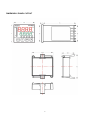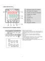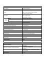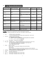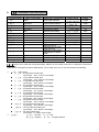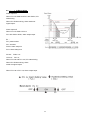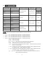
1
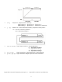
PT-8320 User Manual 1 DIMENSION / PANEL CUTOUT 2 PANEL DESCRIPTION: EXPLANATION FOR TERMINAL WIRING: 3 STANDARD SPECIFICATIONS Power Supply 85~265V AC 50/60 Hz Power Consumption 7VA Maximum Upper:Red 4 digit of 7 segment display Bottom:Green 4 digit of 7 segment display Display 10 segment bar-graph display Thermocouple:J, K, B, N, R, S, T, E RTD:PT100, JPT100 Input Signal Direct Voltage:0~230mV Control Output Relay Output SPST-NO,5A/250V AC Pulse Output(Drive SSR) 12VDC(NPN),20mA (MAX.) Analog 4~20mA ,0~10V DC (MAX.600Ω) Alarm Output SPST-NO,5A/250V AC Alarm Delay Time 0 ~ 99 second Alarm Output Hysteresis Adjustment 0 ~ 9999 degree C Communication Interface RS485(MODBUS) Working Temperature 0 ~ 50℃ (20~85% RH) Cycle Time of Output Control 0 ~ 50.0 seconds Digital 0 ~ 3 digital Digital Filter 1 ~ 100 times Control Method ON/OFF or PID+Fuzzy(Auto Tuning) Input Compensation -1999 ~ 9999 Fraction Value 0.0 ~ 999.9 Setting Range -1999 ~ 9999 Accuracy 0.3%FS ± 1digit Sampling Interval 400ms Memory Retention EEPROM OTHER FUNCTIONS Error code displayed on PV, with sensor error alarm Sensor Error Detection output ability. HBA(Heater Break Alarm), Current error of heater can be detected via CT transformer. Detect the loop break and Heater Break Alarm Or using LBA(Loop Break Alarm) to detect system failure via software. Remote Setting Voltage、Current signal in order to Remote Set Point (RSP) change SV value EVENT function Remote control for executing specific command Re-transmit the voltage、current after the exchange of Re-transmission PV、SV 4 A. ANUE DESCRIPTION Main parameters selection Main Parameters Name of Parameter Description of Parameter PV value Present value SV value Setting value LV-0 Status information LV-1 PID setting LV-2 Advance setting for control Prog Ramp & Soak setting ALM Alarm setting StUP Hardware construction setting EXPA Expansion function setting CoMM Communication setting LoCK Lock function SCAL Analog auxiliary input setting rSP Remote Set Point auxiliary input setting Ct Current transformer input setting Under operating mode, please press MOD button in order to exchange above Main menu selection 5 B. Parameters block description Parameters Display Name of Parameters Description of Parameters Pattern Display the present executing Display Range Default ~ 0 ~/ 0 ~ 0 // rSt pattern Step Display the present executing step Link Display the present link setting Program Ramp & Soak control On/Off Advance Skip to next step / OFF Standby time Display waiting time for start ~ 0 ~ 0 ~ 0 (minute) Elapse time Display schedule of executing time (minute) Repeat time Display style executed time Heater MV Display heater output .~. 0 Cooler MV Display cooler output .~. 0 section shows controller status, mainly for Ramp/Soak information. To go to LV-0, please press MOD once under SV/PV, the details are listed as below: ¾ ¾ ¾ ¾ ¾ ¾ ¾ ¾ ¾ ¾ : Indication of the on-going pattern 0:Not in the Ramp/Soak control mode, which means oPEr = onoF or Pid : Indication of the on-going step 0:Ramp/Soak control not starts yet. SV:Maintain the last SV (EXPA->Pend=SV) after patterns are completed. 1、3、5、7、 9、11、13、15 :Ramp step 2、4、6、8、10、12、14、16:Soak step : Next pattern。(0: there is no next pattern) : Program control: Change is effective while LV2->oPEr not be onoF or Pid. rSt:Reset ramp/soak status, and control/alarm output stop action. rUn:Ramp/soak control begins or continues. Hold:Hold ramp/soak timing :Skip to next step. Ramp=>Soak:SV becomes the setting of the next soak step. Soak=>Ramp: EXPA=>PVSt=PV, PV reaches soak value after ramp time from the current PV. EXPA=>PVSt=SV, PV reaches soak value after ramp time from the current SV setting. :Remaining time before controller actuates (min). :Time performed of the on-going step (min) :Remaining repeat times. :Percentage of manipulate value for the heater. :Percentage of manipulate value for the cooler. 6 C. Parameters block description Parameters display Name of Parameters Description of Parameters Display range Default Tun Auto Tuning / OFF Proportional Proportional parameter ~. 2.0 Integral Time Integral parameter (second) ~ 100 Derivative Derivative parameter ~ 10 Tau Fuzzy parameter . ~. 0.060 Cooling Coefficient Cooling parameter . ~. 1.00 MARE Manual reset . ~. 0 Auto Tune Offset SV Offset during Auto-tuning ~ 0 Heater Hysteresis Control output hysteresis for ~ 0 ~ 0 .~. 5.0 .~. 5.0 / OFF heater Cooler Hysteresis Control output hysteresis for cooler Heater period Cycle time of control heater output (second) Cooler period Cycle time of control cooler output (second) Dead band Dead band control Heater dead band Dead band of heater ~ 0 Cooler dead band Dead band of cooler ~ 0 CT current monitor Display CT Heater burnout Heater break setting -1. ~. 0 section of parameters are used for basic control,P、I、D、tAU、CoEF parameters affect PID+Fuzzy control algorithm performance,theses parameter can be auto calculated by auto-tune function, without the need of complex PID tuning. Fuzzy compensation control makes system response faster and more reliable. To go to LV-1, press MOD twice under SV/PV, and its sub options are listed below: ¾ : Auto tuning on:Auto tuning on oFF:Auto tuning off. When auto tuning is on, controller will start heating and cooling around the setting SV. After two cycles, PID parameters can be calculated. With these PID parameters, the controller can stabilize the system to a desire process value. You can also adopt the oFSt function (especially used during the auto tuning process), to prevent system over-heat during the auto tuning process. 7 ¾ :Proportional Gain parameter。Can be calculated by auto tuning or adjusted manually. This parameter is responsible to the system deviation. When offset occurs, proportional regulator responds to reduce the offset. ¾ :Integral parameter。Can be calculated by auto tuning or adjusted manually. When steady offset exist in a consistent temperature, Integral regulator will start compensating until offset is fixed. ¾ :Derivative parameter。Can be calculated by auto tuning or adjusted manually. Derivative regulator can predict the system trend by rate of change; derivative regulator will fix the offset in advance, before offset happens. ¾ :Fuzzy factor parameter. Can be calculated by auto tuning or adjusted manually. Fuzzy control compensates the insufficiency of PID controller and helps to reach the target based on the deviation and rate of change. Bigger Tau, more Fuzzy compensation! ¾ :Cooling coefficient. Can be calculated by auto tuning or adjusted manually. Cooler proportional gain = P / Coef This function is used in cooling control, to tell the performance of cooler. ¾ :Manual reset. When Integral i=0, and PV>SV, then MV=MArE. ¾ :SV offset setting during Auto tuning When this function is set up, auto tuning will make the system to oscillate around SV + oFSt . For example, SV=200°C;OFST= -10°C. Auto tuning will calculate as SV+OFST=200+(-10)=190°C, to avoid over-heating. ¾ ¾ :Hysteresis for cooler on/off control. :Hysteresis for heater on/off control. During ON/OFF control, control output should be turned off when PV>SV, and turned on when PV<SV. To avoid frequent ON and OFF control, hysteresis can be set. When HYS is set, PV>SV+HYS to turn off the control output, and turned on when PV<SV-HYS. ¾ :Heater control cycle time(sec) ¾ :Cooler control cycle time(sec) For any control output that is not in linear analog signal such as relay and 12V pulse output, signal output status will be ON/OFF only. For better PID result, Time Proportional is used. For example, period is set to be 5 seconds and PID is 30%. (ON)= 30%. 5*0.3=1.5 sec. (OFF)= 70% 5*0.7=3.5 sec. Control output reacts quicker as cycle time gets shorter. When mechanical contact output is used, please consider issue of mechanical life. 8 ¾ ¾ ¾ :Enable/disable dead band control. :Dead band for heater. :Dead band for cooler. Heating and cooling range can be controlled via dead band setting Heater dead band control:If PV>SV+DB-H, heater is not active. Cooler dead band control:If PV<SV+DB-C, cooler is not active. DB-H>0;DB-C>0 Over SV+DB-H deactivates heater Under SV+DB-C deactivates cooler DB-H>0;DB-C<0 Over SV+DB-H deactivates heater Under SV+DB-C 以 deactivates cooler Deactivates heater Deactivates cooler SV Deactivates cooler SV+(DB-H) SV+(DB-C) DB-H<0;DB-C<0 Over SV+DB-H deactivates heater Under SV+DB-C deactivates cooler SV+(DB-C) SV Deactivates heater SV+(DB-H) DB-H<0;DB-C>0 Over SV+DB-H deactivates heater Under SV+DB-C deactivates cooler Deactivates heater Deactivates cooler SV+(DB-C) ¾ Deactivates heater SV+(DB-H) SV Deactivates cooler SV+(DB-H) SVSV+(DB-C) :Display CT (current transformer)input current Install CT input expansion module, it will display relative current value ¾ :Heater break alarm setup: when CT transformer current is lower than SV during heating, it will be considered heater break. Thus, alarm will send out. 9 D. Parameters block description Parameter display Name of Parameters Input Description of Parameters Input signal selection Operation Control mode selection Remote/Local Set Value Dot Unit Multiplier Bias Mode Filter Standby timer LbA detection Time LbA detection Width LED Status Bar Transfer SV Hi Transfer SV Lo SV Remote/unit intput Temperature setting Decimal point setting Temperature unit display PV Multiplier PV compensation input Control mode setting Digital filter Waiting time for control starting (second) Detection time of heater break (second) Detection of temperature differentiation of heater break Bar-graph display Re-transmit SV high value Re-transmit SV low value Display Range ////// //// // / / ~ ~ / .~. ~ / ~ ~ Default K type ~ 0 ~ 1.0 HEAT/CooL/Prog ~ ~ HEAT 100.0 0 OnoF off 0.0 dot1 ℃ 1.000 0.0 H-C 5 0 section is for advanced control parameters, ON/OFF or PID control mode can be configured to achieve the requirement. Under SV/PV mode press 3 times of MOD button, it is for main menu of LV-2, the sub-selection as following: ¾ ¾ : Input signal :K Type thermocouple input Input range:-200~1370°C 0.3%±1Digit。 :J Type thermocouple input Input range:-210~1200°C 0.3%±1Digit。 :T Type thermocouple input Input range:-200~400°C ±2°C±1Digit。 :E Type thermocouple input Input range:-200~1000°C 0.3%±1Digit。 :R Type thermocouple input Input range:-50~1760°C 0.3%±1Digit。 :S Type thermocouple input Input range:-50~1760°C 0.3%±1Digit。 :B Type thermocouple input Input range:250~1820°C ±8°C±1Digit。 :N Type thermocouple input Input range:-200~1300°C 0.3%±1Digit。 :PT Type thermocouple input Input range:-200~850°C 0.3%±1Digit。 :JPT Type thermocouple input Input range:-200~850°C 0.3%±1Digit。 :DC Type voltage input Input range:0~230mV 0.3%±1Digit。 : :ON-OFF; :PID :Program; :Program-ONOFF 10 On/Off mode On/Off mode control is a very common and simple control mode. When the control output is programmed as the heating output and the temperature lower than setting value, control output start to activate; if the temperature is higher than setting value, control output deactivate in order to control the temperature. It also can adjust hysteresis band to reduce the overshooting on the system to achieve the best control and stability. PID mode MV SV PV PID control is corresponding to three constants which are proportional, integral, derivative. P is to handle the immediate error, I is to learn from the past and D is to handle the future. When control output is the heating output, the PT-series will apply PID+ Fuzzy algorithm to calculate a MV value (manipulate value) to be used in determining whether the control output should be strong or weak in order to constantly calculating the deviation of stability and prediction. The built-in Fuzzy control is to enhance the system in stability for achieving the best control and efficient. Program /Program ONOFF Mode Program mode offers 8 patterns temperature control. Every pattern includes temperature setup, time of ramp, time of soak. Measurement unit is minute. The 8 patterns temperature control allows the system to reach the set temperature within the set time of ramp(increase/decrease), and to maintain the set temperature within the set time of soak. It can also utilize Wait Width(EXPA->WAit) to let the system stay close to the setup even if the system is unable to follow the setup perfectly. There are 8 sub-patterns for set up in one pattern. Via Link function, 64 sub-patterns temperature control can be given with ON/OFF and PID control as optional. 11 ¾ ¾ ¾ ¾ ¾ ¾ ¾ ¾ ¾ ¾ ¾ ¾ ¾ ¾ :Remote(RSP) or local SV :Remote mode (RSP); :Local mode。 :Temperature set value; Set value between。 :Decimal point set value。 :decimal point 0 :decimal point 1 :decimal point 2 :decimal point 3 :Measurement Unit setup。℃/℉ :PV magnification adjustment。 :PV Offset input。When PV’s current value and expected value does not match, PV offset input function can be utilized for adjustment.PV = PV*MUL + biAS :Control setup。 :for system heating and cooling。 :for system cooling。 :Digital filter;Decrease static signal。1~100 filter time can be set。 Digital filter can only affect PV value time update, not speed update。 :Wait Width:System can be set to control when the system can be actuated.When Wait Width is set to be 0, there will be no Wait function. :LBA heater burnout time:Set LBA burnout cycle time(second) ,when LbAt is set to be 0,there is no LBA function。 :LBA heater burnout temperature difference:Set LBA burnout temperature difference. When system is being heated and temperature increase is less than the temperature difference within LBA time, controller will assume heater is broken then LBA alarm signal will be sent out. :Bargraphic Indicator :Heating control value,one light represents 10% value. :Cooling control value,one light represents 10% value. :8 modes are active. First light blinks:First mode of temperature increasing/decreasing is active. First light on constantly:First mode of temperature holding is active. Second light blinks:Second mode of temperature increasing/decreasing is active. Second light on constantly:Second mode of temperature holding is active. :Set to re-transfer greatest SV value: :Set to re-transfer smallest SV value: When output is the SV re-transfer analog output, SV can be transferred into the corresponding voltage and current output. Example:TR-H =100.0 TR-L=0.0 Liner output 0~10VDC SV 0.0 ~ 100.0 corresponds to 0~10V analog output 12 E. Parameter Table Parameters display Name of Parameters Description of Parameters Display range Value Pattern NO. Pattern selection ~ 1 Number of steps Steps needed to be performed ~ 8 ~ Set Value Temperature setup ~ 0 ~ Ramp time Time increase/decrease(min) ~ 0 ~ Soak time Time of temperature holding(min) ~ 0 Repeat time Repeat time ~ 0 Link pattern Link pattern ~8 0 Time signal step Output signal step 1 ~ r1 Signal 1 ON time Signal 1 ON time (min) ~ 0 Signal 1 OFF time Signal 1 OFF time (min) ~ 0 Time signal2 step Output signal step 2 ~ r1 Signal2 ON time Signal 2 ON time (min) ~ 0 Signal2 OFF time Signal 2 OFF time (min) ~ 0 Parameter is a multi-pattern control function. Every pattern can perform 8 steps of temperature control. Via link pattern, 64 steps of temperature control can be performed. Press MOD 4 times under SV/PV mode,sub-menu can be selected under the main menu as below: ¾ :8 pattern selection:Total of 8 patterns for selection. It is also the first action pattern among the 8 patterns. ¾ :Step selection:Step 1~8. Temperature increase/decrease, temperature hold can be set in each step. ¾ ~:Temperature setup:Set target temperature in each step. Ex.: SV=50 PV=30 SV1=50 tr1=1 ts1=2 PV starts to increase to reach SV(increase speed is in inverse ratio to ramp time). After 1 minute, SV reaches 50 and temperature begins holding for 2 minutes. ¾ ~:Time of increase/decrease(Ramp):Set time needed(minute) in order to reach the set temperature. ¾ ~:Time of holding(Soak):Time of hold(minute) after ramp time. 13 ¾ ¾ :Pattern Link:Pattern selection followed by completion of each pattern. :Repeat time:Repeat time for each step Default setting=0,Repeat time= 0,Total action= 1 Default setting=1,Repeat time= 1,Total action= 2, and so on. Ex.:Set Link=2 followed by Pattern 1. Link=1 followed by Pattern 2. ¾ ¾ ¾ /:Signal output procedure:signal output setup r1:Temperature increase 1 s1:Temperature holding 1 r2:Temperature increase 2 s2:Temperature holding 2 / :Signal on wait time:Signal output turns on at set wait time /:Signal off wait time: Signal output turns off at set wait time. Signal will be turned off followed by time signal 1~2. Signal will be turned on in specified step. 14 F. Parameter Table Parameters display Name of Parameters Description of Parameters Display range Reset Value Soft Start Alarm soft start / OFF Position 1 Alarm position 1 ~ 0.0 Hysteresis 1 Hysteresis 1 ~ 0.0 Delay Time 1 Delay time 1(sec) ~ 0 Style 1 Style 1 ~ Sty1 , Position 2 Alarm position 2 ~ 0.0 Hysteresis 2 Hysteresis 2(sec) ~ 0.0 Delay Time 2 Delay Time 2 ~ 0 Style 2 Style 2 ~ Sty1 , Position 3 Alarm position 3 ~ 0.0 Hysteresis 3 Hysteresis 3(sec) ~ 0.0 Delay Time 3 Delay Time 3 ~ 0 Style 3 Style 3 ~ Sty1 , Position 4 Alarm position 4 ~ 0.0 Hysteresis 4 Hysteresis 4(sec) ~ 0.0 Delay Time 4 Delay Time 4 ~ 0 Style 4 Style 4 ~ Sty1 , There are 4 sets of alarm parameter setting designed to fit different application condition. In addition, there is Error Alarm function(ALM->StyLE->SErr) for additional protection for your system. Press MOD 5 times under SV/PV mode to go to ALM main menu. Sub-menu: ¾ :Alarm soft start on/off Alarm will go off when system is within the alarm range twice. ¾ :Position 1 setup. ¾ :Hysteresis 1 setup. ¾ :Delay time 1 setup(sec). ¾ :Style 1 selection(Please refer to ¾ :Position 2 setup. ¾ :Hysteresis 2 setup. ¾ :Delay time 2 setup(sec). ¾ :Style 2 selection(Please refer to StyL alarm style description). StyL alarm style description). 15 ¾ :Position 3 setup. ¾ :Hysteresis 3 setup. ¾ :Delay time 3 setup(sec). ¾ :Style 3 selection(Please refer to ¾ :Position 4 setup. ¾ :Hysteresis 4 setup. ¾ :Delay time 4 setup(sec). ¾ :Style 4 selection(Please refer to StyL alarm style description). StyL alarm style description). 16 6.1 Offset High Alarm Alarm Style Alarm output on When PV>=SV+POS1, DY1 starts timing. When DY1 finishes timing, alarm sends out signal output. Alarm output off When PV<SV+POS1-HYS1, alarm output stops. Ex.: PV= present value SV= set value POS1= Alarm set point DY1= Alarm delay time SV=60; POS1=10; HYS1=5; DY1=5; When PV>=70, DY1 starts timing. When DY1 finishes timing, alarm sends out signal output. When PV<65, alarm output stops. 17 6.2 Offset High Alarm Alarm output on When PV>=SV-POS1, DY1 starts timing. When DY1 finishes timing, alarm sends out signal output. Alarm output off When PV<=SV-POS1-HYS1, alarm output stops. Ex.: PV= present value SV= set value POS1= Alarm set point DY1= Alarm delay time SV=60; POS1=10; HYS1=5; DY1=5; When PV>=50, DY1 starts timing. When DY1 finishes timing, alarm sends out signal output. When PV<45, alarm output stops. 18 6.3 Offset Low Alarm Alarm output on When PV<=SV-POS1, DY1 starts timing. When DY1 finishes timing, alarm sends out signal output. Alarm output off When PV>=SV-POS1+HYS1, alarm output stops. Ex.: PV= present value SV= set value POS1= Alarm set point DY1= Alarm delay time SV=60; POS1=10; HYS1=5; DY1=5; When PV<=50, DY1 starts timing. When DY1 finishes timing, alarm sends out signal output. When PV>=55, alarm output stops. 19 6.4 Offset Low Alarm Alarm output on When PV<=SV+POS1, DY1 starts timing. When DY1 finishes timing, alarm sends out signal output. Alarm output off When PV>=SV+POS1+HYS1, alarm output stops. Ex.: PV= present value SV= set value POS1= Alarm set point DY1= Alarm delay time SV=60; POS1=10; HYS1=5; DY1=5; When PV<=70, DY1 starts timing. When DY1 finishes timing, alarm sends out signal output. When PV>=75, alarm output stops. 20 6.5 Out-Range Alarm Alarm output on When PV<=SV+POS1 or PV<=SV-POS1, DY1 starts timing. When DY1 finishes timing, alarm sends out signal output. Alarm output off When PV>=SV+POS1+HYS1 or PV<=SV+POS1-HYS1, alarm output stops. Ex.: PV= present value SV= set value POS1= Alarm set point DY1= Alarm delay time SV=60; POS1=10; HYS1=5; DY1=5; When PV<=50 or PV>=70, DY1 starts timing. When DY1 finishes timing, alarm sends out signal output. When PV>=55 or PV<=65, alarm output stops. 21 6.6 In-Range Alarm Alarm output on When PV>=SV-POS1 and PV<=SV+POS1, DY1 starts timing. When DY1 finishes timing, alarm sends out signal output. Alarm output off When PV<=SV-POS1-HYS1or PV>=SV+POS1+HYS1, alarm output stops. Ex.: PV= present value SV= set value POS1= Alarm set point DY1= Alarm delay time SV=60; POS1=10; HYS1=5; DY1=5; When PV>=50 and PV<=70, DY1 starts timing. When DY1 finishes timing, alarm sends out signal output. When PV<=45 or PV>=75, alarm output stops. 22 6.7 Absolute Value High Alarm Alarm output on When PV>=POS1, DY1 starts timing. When DY1 finishes timing, alarm sends out signal output. Alarm output off When PV<=POS1-HYS1, alarm output stops. Ex.: PV= present value SV= set value POS1= Alarm set point DY1= Alarm delay time SV=10; POS1=60; HYS1=5; DY1=5; When PV>=60, DY1 starts timing. When DY1 finishes timing, alarm sends out signal output. When PV<=55, alarm output stops. 23 6.8 Absolute Value Low Alarm Alarm output on When PV<= POS1, DY1 starts timing. When DY1 finishes timing, alarm sends out signal output. Alarm output off When PV>=POS1+HYS1, alarm output stops. Ex.: PV= present value SV= set value POS1= Alarm set point DY1= Alarm delay time SV=60; POS1=10; HYS1=5; DY1=5; When PV<=10, DY1 starts timing. When DY1 finishes timing, alarm sends out signal output. When PV>=15, alarm output stops. 6.9 SErr Signal Error Alarm Under this alarm mode, alarm will go off when PV encounters irregular condition. When PV indicates [––––] – Sensor break [U U U U] – Exceed low limit measuring range [o o o o] – Alarm goes off if exceeding high limit measuring range 24 G. Parameter Table Parameters display Name of Parameters Out1 Out2 Sub1 Sub2 Description of Parameters control/alarm/output transmission Display range Reset Value ,,, Heat ~,, Cool ,,, ALM1 ,,, ALM2 AUX1 AUX2 AUX3 AUX4 Event 1 Event 2 ,,, AUX input ~ None ,,, Event input Event 3 Event 4 Direction 1 Direction 2 Input direction Direction 3 (forward or reverse) Direction 4 ,, / None Hi Users can set parameters according to application environment and habit. ¾ : Out 1 control/alarm/output transmission:Selectable output types ¾ : Out 2 control/alarm/output transmission:Selectable output types ¾ : Sub 1 control/alarm/output transmission:Selectable output types ¾ : Sub 2 control/alarm/output transmission:Selectable output types :Heater control output :Cooler control output ~:Alarm output to be performed with ALM for detail setup. :Heater break alarm to be performed with CT transformer. :Loop break alarm to detect heater break by software. This function has to be performed with LV-2→LbAt and LbAW. :Controller has to work with analog output to transfer PV value to voltage/current value. For module 0-10vDC、4-20mA, please refer to SCALE. :Controller has to work with analog output to transfer SV value to voltage/current value. For module 0-10vDC、4-20mA, please refer to LV-2→tr-H and tr-L. ~:In specified steps, ts1~2 will send out signal after On Wait Time and ts1~2 will be turned off after Off Wait Time. 25 Ex.: ts1=S2, on=2, off=3 After 2 minutes in Temperature Holding Step 2, ts1 will be on. After another 1 minute, it will be off again. After ts-1~2 goes to the next step, all signal will be off until it reaches specified steps. :When 8 steps are completed, Pend will receive a pulse signal. :When performing 8 steps, Stg will receive pulse signal when it is in ramp or soak Ex.:To correspond SV 0.0~100.0 to 0-10VDC output, please set LV-2→tr-H = 100, LV-2→tr-L = 0 ¾ :Aux 1 input ¾ :Aux 2 input ¾ :Aux 3 input ¾ :Aux 4 input Offer different signal input including remote SV value(RSP)、remote Event, current transformer, and CT input. :Remote SV value setup with 0-10V,0-20mA module input. Please go to rSP in main menu for detail setup. :Current transformer input for current measurement with Ct module. Please go to Ct in main menu for detail setup. ~:Specified Event can be set with Event module. ¾ : Event 1 input ¾ : Event 2 input ¾ : Event 3 input ¾ : Event 4 input ~:Specified Event can be set with Event module. Under Stup→EVt1~4 in main menu,corresponding Event(Reset,Remote 26 -Local ,Manual, Hold, Advance) can be set。Simply switch on to perform. :Switch on => LV-2->r-L=on Switch off => LV-2->r-L=oFF :Switch on => Switch between manual and standard mode :Switch on => LV-0->Prog=rSt Switch off => LV-0->Prog=rUn :Switch on => LV-0->Prog=HoLd Switch off=>LV-0->Prog=Retrieve Hold original setting :Switch on => LV-0->AdV=on ¾ :Output direction 1(Forward/reverse) ¾ :Output direction 2(Forward/reverse) ¾ :Output direction 3(Forward/reverse) ¾ :Output direction 4(Forward/reverse) Select Forward output or Reverse Output with Out1, Out2, Sub1, Sub2. 27 H. Parameter Table Parameters display Name of Parameters Description of Parameters Set value upper limit SV upper limit setup , Display range Reset Value ~ 9999 ~ -1999 SV-H>SV-L Set value lower limit SV lower limit setup , SV-L<SV-H AT hysteresis Auto Tune hysteresis . ~. 0.5 Power ON Power on // rSt / Pend condition Pend condition / rSt Wait width Wait width ~ 0 PV Start PV/SV start / PV Return display SV/PV main menu Auto //// 0 return(sec) // HBA latch HBA latch alarm / OFF Reset default Default vale retrieval / OFF Users can set parameters according to application environment and habit. ¾ :SV value upper limit setup:To limit maximum SV value, preset value is 9999. ¾ :SV value lower limit setup:To limit minimum SV value, preset value is -1999. ¾ :Auto Tune hysteresis setup:To avoid signal interruption during Auto Tune which causes faulty calculation, At-H value is preset to be 0.5. System will be heated to PV+0.5, and cooled to PV-0.5 during Auto Tune. ¾ :Power on setup:This mode is designed for 8 patterns(Program mode). It can set Continue, Reset, Run and Manual when system is on. :Controller turns on. Program mode is in reset condition. Alarm will not go off. :Controller is in manual mode when it is turned on. :Controller turns on. Program mode resets automatically. Con:Restore the program status before power failure, and continue operating (rSt、rUn、Con options are effective while LV2->oPEr=Prog or P-nF) ¾ :Pend status:Set controller’s mode after 8 patterns finish running. It can be set as Reset. Controller will return to rSt after 8 patterns complete and alarm does not go off.(LV0->Prog=rSt) It can be set as SV. Controller will remain in the last SV after 8 patterns complete and continues functioning. ¾ :Wait Width:When performing 8 patterns, ∣PV-SV∣has to be smaller than Wait width in order to enter the next step and follow the setting. Default value 0: Disable. 28 ¾ : Ramp/Soak initial SV setting, the SV initial value of the first step or when skip into ramp step, the SV initial value accumulate from the current PV or according to the SV setting. PV:Perform based on PV setup SV:Perform based on SV setup ¾ :PV/SV main menu auto return:Display will automatically returned to PV/SV main menu when there is no new setup for time input. Setup range is oFF、10、20、30、40、50、60.(Default oFF Not return to PV/SV automatically,Unit:second) ¾ :Alarm latch:HBA latch alarm can be set. When latch mode is on, HBA alarm not de-energize while system outside the alarm range. (default:OFF) ¾ :Preset default value retrieval(reset):This mode can retrieve preset default value. 29 I、 List of parameters Parameters display Name of Parameters Description of Parameters ID Identification BPS. Baud rate Style Transmitting Style Format Transmitting Format Hex/Ascii Hex Time Out Setting for Time limit ~ 100 Allow Write Allow writing for parameters / ON ¾ :Identify the address of control unit ¾ :Selection for Baud Rate communication Display range Default ~ 1 Describe below 9600 Describe below 600 :Baud rate 600 1200 :Baud rate 1200 2400 :Baud rate 2400 4800 :Baud rate 4800 9600 :Baud rate 9600 19200:Baud rate 19200 38400:Baud rate 38400 ¾ :Selection for communication style 8n1:None parity check, Stops one bit 8n2:None parity check, Stops two bits 8o1:Odd check, Stops one bit 8E1:Even check, Stops one bit ¾ :Selection for communication format HEH.:Hex mode AS.Ci:ASCII mode ¾ :Setting for time limit ¾ : Allow writing, setting the communication with parameters writing(ON/OFF) 30 8n1 J、 Parameters block description Parameter Display Name of Parameters LABEL Description of Parameters Setting Range Default Lock selection ~ LB00 Through LAbe parameter setting, it is adjust the main menu selectable and good for use friendly, avoid the possibility mistake in setting function. LB00 LB01 LB02 LB03 LB04 PV/SV ● ● ● ● ● LV-0 ● ● LV-1 ● ● ● LV-2 ● ● ● Prog ● ● ALM ● ● ● StUP ● EXPA ● CoMM ● LoCK ● ● ● ● ● SCAL ● rSP ● Ct ● CALI ● MANU ● ● ● ● ● ● ● CALI:Calibration selection MANU:Manual selection 31 K. Parameter Table Parameter Display Name of Parameters Description of Parameters Setting Range Pre-set value Scale Hi Greatest PV value ~ 100.0 Scale Lo Lowest PV value ~ 0.0 Sensor input voltage Sensor AD voltage Sensor Hi Greatest voltage input .~. 0.25 Sensor Lo Lowest voltage input .~. 0.1 Scale Enable Scale enable switch / OFF ¾ :Greatest PV value:Set PV value in Span voltage. ¾ :Lowest PV value:Set PV value in Zero voltage. PV can be re-transmitted for t-PV(Transfer PV). ¾ :Sensor AD voltage:Set SCHi、SCLi. ¾ :Greatest voltage input:Set greatest measuring voltage in Sensor input. ¾ :Lowest voltage input:Set lowest measuring voltage in Sensor input. ¾ :Input switch:ON/OFF voltage input in PV display Ex. 1:PV value 0.0~ 100.0 corresponds to 0~10V DC output in SUB2 terminal Ex. 2:0-10mV value corresponds to PV 0.0~200.0 in Sensor output Steps: 1、 2、 3、 4、 Steps: 1、 Connect 0-10mV DC to PT8 in Sensor output terminal. 2、 SCAL→SCH = 200.0 3、 SCAL→SCL = 0.0 4、 Input 0V to observe SCAL→SEnS and input value into SCAL→SCLi 5、 Input 10mV to observe SCAL→SEnS and input value into SCAL→SCHi 6、 SCAL→SCEN = ON 7、 Back to main menu Input 0mV, PV = 0.0? Input 10mV, PV = 200.0? 8、 Complete setup StUP→SUB2 = t-PV in main menu SCAL→SCH = 100.0 in main menu SCAL→SCL = 0.0 in main menu Complete setup 32 L. Parameter Table Parameter Display Name of Parameters Description of Parameters Setting Range Pre-set value Scale Hi Greatest SV Value(RSP) ~ 10.0 Scale Lo Lowest SV Value(RSP) ~ 0.0 AD Voltage AD Voltage Input Hi Set Span Voltage .~. 2.264 input Lo Set Zero Voltage .~. 0.072 Note:LV-2 → r-L has to be turned on in order to perform each mode. ¾ :Greatest SV Value:Set greatest SV value in Span voltage. ¾ SCL :Lowest SV Value:Set lowest SV value in Zero voltage. ¾ :Sensor AD Voltage:To calibrate zero, span voltage ¾ : Set Span Voltage:Set greatest voltage output for AD. ¾ :Set Zero Voltage:Set lowest voltage value for AD. Ex.:Set input of 0~10vdc in AUX1 SV value: 0.0~100.0 Steps: 1、 Connect 0-10VDC output to PT8(AUX1)(RSP 0-10Vdc) 2、 Select rSP under StUP→AUX1 in main menu. 3、 Select rSP→SCH = 100.0 in main menu 4、 Select rSP→SCL = 0.0 in main menu 5、 Input 0V to observe rSP→AD.Input value into rSP→SCLi 6、 Input 10v to observe rSP→AD. Input value into rSP→SCHi 7、 Select LV-2→r-L = ON in main menu 8、 Back to PV/SV main menu Input 0v, SV = 0.0 Input 10v,SV = 100.0 9、 Complete setup 33 M. Parameter Table Display Name Description Range Preset Value Scale Hi Scale Hi(CT current) ~ 35.0 Scale Lo Scale Lo(CT current) ~ 0.0 AD Voltage AD Voltage Indication Input Hi Set Span voltage .~. 2.5 input Lo Set Zero voltage .~. 0.1 Note:Tolerance of greatest CT current input is 30mA ¾ :Scale Hi:Set greatest CT value in Span voltage ¾ :Scale Lo:Set lowest CT value in Zero voltage ¾ ¾ :Set Span voltage:。 ¾ :Set Zero voltage:。 :Sensor AD Voltage:To calibrate zero, span voltage Ex.:When hardware detects heater breakage, CT input utilizes AUX1 and SUB1 to send alarm signal. Steps:(Please refer to CT input module in the right) 1、 Connect CT transformer to PT8(AUX1)。 2、 Select Ct under StUP→AUX1 in main menu. 3、 Select HbA under StUP→SUB1 in main menu. 4、 Observe AD voltage exceeds 0.100v when heater is on under Ct→AD in main Ex.:Calibrate CT transformer: Transformer input is 5A;Ratio is 1000:1 menu. If AD voltage exceeds 0.100v, it 1、 Main menu Ct→SCH = 5.0 means transformer is connected correctly. 2、 Main menu Ct→SCL = 0.0 3、 Input 0A to observe 5、 Observe Ct value(HNC) when heater is off and (HNO) when heater is on under Ct→AD display,input value into LV-1→Ct in main menu. SCLi 4、 Input 5A to observe AD,input 6、 Input proper set value (HNC < Hb < HNO) value into SCHi under LV-1→Hb in main menu. Normal 5、 Complete setup. setup is 70% of HNO. 7、 Complete setup. 34 N、 Parameter Table Display Name Description Analog input calibrate Sensor input calibration Analog output1 calibrate Analog output1 calibration Analog output2 calibrate Analog output2 calibration Analog output3 calibrate Analog output3 calibration Analog output4 calibrate Analog output4 calibration Fuzzy Switch FuzzySwitch TEMP121 information Temperature Information Range Preset Value / ON Calibration mode can be performed based on each input/output. To go to Cali main menu, please press and hold for 5 seconds under SV/PV mode. To go back to SV/PV mode, please press and hold ¾ for 5 seconds under Fine-Tek mode. :Sensor Input Calibration:After calibration, voltage and resistance can be measured accurately. Sub-menu: 1、PAS :Input correct password to enter.(password:12) 2、0mV :Calibrate 0mv input. 3、50mV:Calibrate 50mV input. 4、r100:Calibrate 100Ω input. 5、r300:Calibrate 300Ω input. 6、Adjt: Temperature compensation calibration. PV = PV + Adjt (Please see Example 1 for detail) ¾ ~:Analog Output Calibration: Calibration will be performed based on each analog output to get accurate Span & Zero voltage Sub-menu: 1.AdjF:Calibrate Span voltage output(0~10v), current(4~20mA) 2.Adj0:Calibrate Zero voltage input(0~10v), current(4~20mA) (Please see Example 2 for detail) ¾ :Fuzzy Switch:Whether Fuzzy is to be activated when setting up PID.(Preset Value:ON) ¾ :IC Temperature Indication:To indicate temperature information. IC temperature for thermocouple input. PV = TC temperature difference + internal IC temperature 35 Example 1:Calibrate Sensor input Example 2:Calibrate OUT1 analog output 0~10v DC Setup: 10、 Connect calibrator with sensor input Setup: for 5 seconds to 11、 Press and hold 1、 Connect calibrator with analog output 2、 Press and hold enter Cali mode enter Cali mode 12、 Select AiC 13、 Press under Aic→PAS = 12 3、 Select AoC1 4、 Press 14、 Set calibrator output= 0mV 15、 Press to enter Aic→0mv to edit. Press until value is stable, then press to confirm. then press 5、 Press until value is stable, then press to confirm. then press Press to enter Aic→r100 to edit. Press until value is stable, then press to confirm. Note:(Please follow RTD wiring steps when calibrating) 20、 Set calibrator= 300Ω 21、 Press to enter Aic→r300 to edit. Press until value is stable, then press to confirm. Note:(Please follow RTD wiring steps when calibrating) 22、 Press Press to get 10.00v. to enter AoC1→Adj0 to 、 to enter Aic→r300 to edit. to enter Aic→Adjt to edit error of room temperature and present temperature IC. Note:(Please refer present temperature IC in inFo→tEMP) 23、 Setup complete. 36 to get 0.00v. to confirm. 6、 Setup complete. 18、 Set calibrator output= 100Ω 19、 Press 、 edit. Observe calibrator voltage value, to enter Aic→50mv to edit. Press to enter AoC1→AdjF to edit. Observe calibrator voltage value, 16、 Set calibrator output= 50mV 17、 Press for 5 seconds to O、 Parameters block description Parameter Name of Parameters Description of Parameters Setting Range Default Manual operation Display PV value ~ Heater MV Control heater output manipulate .~. 0 .~. 0 value Cooler MV Control cooler output manipulate value ¾ :Display PV value ¾ :Control heater output manipulate value ¾ :Control cooler output manipulate value 37