1
Instrumentation Scientifique de Laboratoire
FZP 5G2s
User’s Manual
Instrumentation Scientifique de Laboratoire - BP 70285 - 14653 CARPIQUET CEDEX FRANCE
Phone: (+33) 2.31.26.43.00 Fax: (+33) 2.31.26.62.93 Web site: http://www.isl-france.com
Page 2
FZP 5G2s User's Manual
DOCV226A011-C
Historical Review
Revision
§ concerned
Modification descriptive
Date
Original issue
05/15/03
Part 1§ 4.3.3.1
ISL Alan® manager software available on the FZP 5G2s analyzers
Part 1§ 2.4
Cleaning recommendations of the detection cell
Part 2 § 2.3.3
Update of the end of test messages
Appendix B
Detailed characteristics of the RS 232C link communication protocol
Part 1 § 2.1
Updating and adding of the standard methods ASTM D7153 and
IP529
Warning; Part 1 §
2.2.2 & 5
Adding of an advertising on Class IIIA laser detection cell hazards
Part 2 § 2.1
Modification of explanations concerning the Other menu
index
A
B
C
DOCV226A011-C
FZP 5G2s User's Manual
01/26/04
09/21/05
Page 3
ISL(c) copyright
The FZP 5G2s Analyzer and this manual are protected by copyright.
Reproduction of the unit will result in prosecution.
All rights to the manual are reserved. Reproduction in any form, including in the form of excerpts, shall require written permission from
the copyright holder.
ISL FZP 5G2s Software(c) 2003, ISL
This present software is owned by ISL and is registered with the « Agence pour la Protection des Programmes », 249 rue de Crimée 75019 Paris. It is protected in France by the « Code de Propriété Intellectuelle » laws and internationally by international treaty
provisions, and all other applicable national laws. It must not be copied, reproduced, adapted, translated, rented or disassembled. This
also applies to the accompanying manuals.
INFORMATION
Information in this document is subject to change without notice and does not represent a commitment on the part of ISL. ISL provides
this document "as is", without warranty of any kind, either expressed or implied, including, but not limited to, the particular purpose. ISL
may make improvements and/or changes in this manual or in the product(s) and/or the program (s) described in this manual at any
time. This product could include technical inaccuracies or typographical errors. Changes are periodically made to the information
herein; these changes may be incorporated in new editions of the publication. Reproduction of any part of this manual without express
written permission is forbidden.
Translation in foreign local language (other than French or English)
Translation in other language than French and English have no contractual value and have been performed under responsibility of the
local distributor.
In any case the reference of the present literature will be the French and/or English release provided under ISL copyright.
Page 4
FZP 5G2s User's Manual
DOCV226A011-C
Reserved for public relations department
N° ................................
Date .............................
CUSTOMER
REPORT
PURPOSE
I wish to
Report an error
Submit a suggestion / a comment
Get more information
In the area of
Hardware
Software
Manual
ANALYZER ENVIRONMENT (please be complete)
• HARDWARE
Type of Analyzer: FZP 5G2s
Serial N° : ...................................................
Options :
Parallel printer
Graphic printer
Plotter
RS232C interface
Current loop interface
Other : ......................................................
• SOFTWARE
Version : ........................................................
ATTACHED SHEETS
Listing
Diskette
Drawing
Text
Other
PROBLEM DESCRIPTION / COMMENTS
SUBMITTED BY
Name :
Company :
Address :
Phone :
Fax :
Date:
Send this report to your local Sales office or to Groupe ISL - Service Clients
BP 70285
14653 CARPIQUET CEDEX FRANCE
Phone : (+33) 2.31.26.43.00 – Monday through Friday from 9 :00 a.m. to 5 :00 p.m. French Time
Fax : (+33) 2.31.26.62.93
Web site: www.isl-france.com
DOCV226A011-C
FZP 5G2s User's Manual
Page 5
Page intentionally blank.
Page 6
FZP 5G2s User's Manual
DOCV226A011-C
Caution
This ISL Analyzer has been carefully designed, manufactured and inspected
for quality. It has been equipped with a number of safety features.
However, the use of this Analyzer may involve the handling of solvents,
chemicals, and other potentially dangerous flammable, toxic, etc.) materials.
Please exercise caution when handling these materials while operating the
Analyzer.
Please:
read the manual
wear proper protective clothing
perform all suggested service procedures
use care to prevent accidents
The manufacturer accepts no responsibility for any damage or liability arising
from the use of Analyzers.
Use of Non-ISL Products and Accessories. Defects or damage that result from
the use of Non-ISL branded or certified Products, Accessories, Software or
other peripheral equipment are excluded from warranty.
CAUTION! Laser radiation when open the detection cell: Disconnect the
analyzer from the mains.
This label is located on the
detection cell.
DO NOT STARE INTO BEAM: CONSEQUENCES COULD BE
IRREVERSIBLE.
The use of optical instruments with this product will increase eye hazard: The FZP
5G2s is equipped with a Class IIIA laser detection cell. As the laser beam used is
harmful to eyes, do not attempt to disassemble the cell. Refer servicing to
qualified personnel only.
DOCV226A011-C
FZP 5G2s User's Manual
Page 7
Page intentionally blank.
Page 8
FZP 5G2s User's Manual
DOCV226A011-C
Contents
PART 1 GENERAL ........................................................................................................................................ 1-13
1. INTRODUCTION
1-15
1.1.
1.2.
1.3.
1.4.
ISL company profile ...........................................................................................................................................1-15
About this manual ...............................................................................................................................................1-16
Typographical conventions .................................................................................................................................1-16
Meaning of symbols............................................................................................................................................1-16
2. TYPE OF ANALYZER
1-17
2.1. FZP 5G2s product overview ...............................................................................................................................1-17
2.2. Technical specifications ......................................................................................................................................1-17
2.2.1. Operation in ambient conditions ....................................................................................................................1-17
2.2.2. Features..........................................................................................................................................................1-17
2.2.3. Power supply .................................................................................................................................................1-17
2.2.4. Dimensions ....................................................................................................................................................1-17
3. CARE IN USE
1-18
3.1. Care in the use of testing and cleaning equipment ..............................................................................................1-18
3.2. Precautions to take when using built-in cooling Analyzers.................................................................................1-18
4. UNPACKING AND INSTALLATION
1-18
4.1. Care in unpacking ...............................................................................................................................................1-18
4.2. Installing the FZP 5G2s: unlocking the shock absorbers ....................................................................................1-18
4.3. Connections ........................................................................................................................................................1-19
4.3.1. Connection to the mains ................................................................................................................................1-19
4.3.2. Connecting the printer ...................................................................................................................................1-19
4.3.3. FZP 5G2s / PC link........................................................................................................................................1-19
5. DESCRIPTION OF THE DEVICE
6. THE USER INTERFACE
1-21
1-22
6.1. Front panel ..........................................................................................................................................................1-22
6.1.1. The LCD ........................................................................................................................................................1-22
6.1.2. Backlight setting ............................................................................................................................................1-22
6.2. The control keys..................................................................................................................................................1-23
6.3. The Welcome display..........................................................................................................................................1-23
PART 2 USE OF THE FZP 5G2S WITH PRE-INSTALLED PRODUCTS ............................................. 2-25
1. INTRODUCTION
2-27
2. THE FIRST TEST
2-27
2.1. Selection of a pre-installed product.....................................................................................................................2-29
2.2. Characterization of the test..................................................................................................................................2-29
2.2.1. Sample identifying.........................................................................................................................................2-29
2.2.2. Operator ID....................................................................................................................................................2-29
2.2.3. Text entry display ..........................................................................................................................................2-30
2.3. Initiating the test .................................................................................................................................................2-31
2.3.1. Procedure.......................................................................................................................................................2-31
2.3.2. Test in progress..............................................................................................................................................2-31
2.3.3. End of test......................................................................................................................................................2-32
2.4. Cleaning the detection cell ..................................................................................................................................2-32
PART 3 ADVANCED USE OF THE FZP 5G2S.......................................................................................... 3-33
1. INTRODUCTION
3-35
2. THE MAIN LEVEL SCREENS
3-35
3. RESULTS DISPLAYING AND PRINTING: THE "RESULTS" MENU
3-37
3.1. Result displaying from result memory ................................................................................................................3-37
3.2. Result printing.....................................................................................................................................................3-40
4. PRINTING AND PRINTER SETUP: THE “PRINT” MENU
3-41
4.1. Service printing...................................................................................................................................................3-41
4.2. Printer setup ........................................................................................................................................................3-41
DOCV226A011-C
FZP 5G2s User's Manual
Page 9
5. TEST SETTING AND PRINTING: THE “RUN ENVIRONMENT” MENU
3-43
5.1. Run parameters of a product................................................................................................................................3-44
5.2. List of operator names.........................................................................................................................................3-45
6. ALARM TREATMENT
3-46
6.1. Types of alarm.....................................................................................................................................................3-46
6.1.1. Failure alarms.................................................................................................................................................3-46
6.1.2. Warning alarms ..............................................................................................................................................3-46
6.2. Displaying alarms, stopping the buzzer...............................................................................................................3-46
6.3. Alarm processing.................................................................................................................................................3-46
6.4. Failure alarms......................................................................................................................................................3-47
6.4.1. Memory failure ..............................................................................................................................................3-47
6.4.2. “Low battery”.................................................................................................................................................3-47
6.4.3. “Signal conditioning (A/D Cnv)”...................................................................................................................3-47
6.4.4. “Cooling circuit”............................................................................................................................................3-47
6.4.5. “Heating circuit” ............................................................................................................................................3-48
6.4.6. “Sample temperature safety”..........................................................................................................................3-48
6.4.7. “Cooling unit temperature safety”..................................................................................................................3-48
6.4.8. “Cooling unit stroke control safety”...............................................................................................................3-48
6.4.9. “Cooling unit board link safety” ....................................................................................................................3-48
6.5. Warning alarms ...................................................................................................................................................3-48
6.5.1. “End of test: Freeze point detected”...............................................................................................................3-48
6.5.2. “End of test: Freeze Pt not detected”..............................................................................................................3-48
6.5.3. “End of test: Crystall. not detected”...............................................................................................................3-48
6.5.4. Buzzer modulation setup................................................................................................................................3-49
6.6. Alarms historical .................................................................................................................................................3-49
7. CONFIGURATION: THE "SETUP" MENU
3-50
7.1. Power on parameters: the "General" menu..........................................................................................................3-51
7.2. Run parameters: the "Run" menu ........................................................................................................................3-51
7.3. Configuring alarms : the "Alarm" menu..............................................................................................................3-51
7.4. Personalization and access authorization to level 1: the "Lab." menu.................................................................3-52
7.5. Printer configuration: the "Printer" menu............................................................................................................3-52
7.6. FZP 5G2s
PC communication: the "PC Link" and "RS232" menus ..............................................................3-52
7.6.1. RS232C link setup: the "RS232" menu..........................................................................................................3-53
7.6.2. Alan® link setup: the “PC link” menu ...........................................................................................................3-54
7.7. Date/Time setting: the "Clock." menu.................................................................................................................3-54
7.8. The "Service" menu.............................................................................................................................................3-55
7.9. The ISL menu ......................................................................................................................................................3-55
7.10. The About FZP 5G2s menu.................................................................................................................................3-55
8. ACCESS LEVELS AND PASSWORD : THE "ACCESS" MENU
3-56
PART 4 MAINTENANCE OF THE FZP 5G2S .......................................................................................... 4-57
1. MEASUREMENT AND DIAGNOSTIC: THE "SERVICE" MENU
4-59
1.1. Measurement displaying on the FZP 5Gs Analyzer: the “Measures” menu ........................................................4-59
1.2. Diagnostic aid......................................................................................................................................................4-60
1.3. Cooling compressor diagnostic ...........................................................................................................................4-60
2. ADJUSTMENT: THE "QUALITY" MENU
4-61
2.1. Sample probe correction table: the "Correct Table" menu ..................................................................................4-61
2.2. Calibration of sample temperature measurement: the "Samp. T. Calib." menu...................................................4-62
2.2.1. Tools required ................................................................................................................................................4-62
2.2.2. Procedure .......................................................................................................................................................4-62
3. THE “SERVICE” MENU OF THE MAIN PRINTING MENU
4-64
3.1. Regulation monitoring.........................................................................................................................................4-64
3.2. Internal parameters ..............................................................................................................................................4-64
4. THE “SERVICE” MENU OF THE “SETUP” MAIN MENU
4-65
4.1. Entering regulation values: the "Regul." menu....................................................................................................4-66
4.2. Entering calibration values: the "Calib." menu....................................................................................................4-66
4.3. Entering detection values: the "Detect." Menu....................................................................................................4-66
4.4. File download command: the “ISL UDS" menu ..................................................................................................4-66
4.4.1. Transfer procedure .........................................................................................................................................4-66
4.4.2. Installation and start-up of the downloading program....................................................................................4-66
4.4.3. User-requested transfer ..................................................................................................................................4-67
4.4.4. Transfer fails or screen not lit ........................................................................................................................4-68
5. MAINTENANCE
4-69
5.1. Control Unit housing cover disassembling..........................................................................................................4-69
5.2. Location of the Acquisition Board ......................................................................................................................4-69
Page 10
FZP 5G2s User's Manual
DOCV226A011-C
APPENDIX A – PRINTING TYPE EXAMPLES............................................................................................ 71
1 - RESULT TICKET PRINTING – DETAILED FORMAT (WITH PRODUCT)
73
2 - PRODUCT PARAMETER PRINTING
73
73
3 - OPERATOR NAME LIST PRINTING
4 - CALIBRATION TICKET PRINTING
73
5 - ANALYZER MEASURE PRINTING
73
6 - INTERNAL PARAMETER PRINTING
74
APPENDIX B – RS232 LINK FEATURES ON FZP 5G2S............................................................................. 77
1 - INTERFACE FEATURES
79
2 - OUTLET CONNECTOR BROACHING
79
3 - COMMUNICATION PROTOCOLS
80
4 - ENQ / ACK PROTOCOL DETAILS
81
5 - TRANSMITTED DATA
82
5.1 5.2 5.3 5.4 5.5 -
Message format ...................................................................................................................................................... 82
The result message ................................................................................................................................................. 82
The run context message........................................................................................................................................ 83
The test product message ....................................................................................................................................... 84
RS232 link test message......................................................................................................................................... 84
6 - RS232 COST
84
APPENDIX C - SEQUENCE CHARTS............................................................................................................ 85
1 - TEST LAUNCH DIAGRAM
87
2 - ACTION CHART
88
INDEX
INDEX
........................................................................................................................................................... 89
91
FZP 5G2S SPARE PART LIST ...................................................................................................DOCV226X200
UNLOCKING THE SCHOCK-ABSORBER .............................................................................DOCV226X001
DOCV226A011-C
FZP 5G2s User's Manual
Page 11
Page intentionally blank.
Page 12
FZP 5G2s User's Manual
DOCV226A011-C
Part 1
General
Page intentionally blank.
Page 1-14
FZP 5G2s User's Manual
DOCV226A011-C
Introduction
1.Introduction
1.1. ISL company profile
We would like to take this opportunity to thank you for choosing ISL product. We are confident that you will be
completely satisfied with your new Analyzer and we hope that you continue to call on us for all of your laboratory’s
petroleum testing needs. Before you begin, we ask you to take a few minutes to become acquainted with ISL and its
history.
ISL’s beginnings go back to 1975, when a group of engineers and scientists from the heart of the Northern France’s
petrochemical industry began seeking ways to automate petroleum testing. The neighboring industry served as an
excellent research and development proving ground for their new equipment.
By the end of 70’s, several quality instruments had been developed and were being marketed in Europe under
ATPEM Trademark.
The most famous of these new instruments was the CPP 97, Automatic Cloud and Pour Point Analyzer. Introduced
in the early 1980’s, its successor, the CPP97-6, revolutionized cold flow testing enabling up to six tests automatically
and simultaneously.
Adding new automatic instruments each year, ATPEM soon became a worldwide leader in automatic petroleum test
instrumentation. In 1986, they expanded operations, reorganizing into the company now knows as ISL.
Striving to maintain close contact with customers in over 75 countries, ISL has since grown, founded Sales & Service
branches on each continent. With design, marketing, service and support operating together under the ISL roof, the
company reached “a new dimension” in 1993 by obtaining ISO 9002 certification from the BVQI. Working hard to
extend our quality assurance program, we received ISO 9001 certification in 1995.
Though best known for distillation, viscosity testing, cold behavior instrumentation, flash point, evaporation loss,
oxidation, and asphalt testing equipment, ISL's contributions to automated petroleum testing continue to grow. With
more than 10 patents to date, ISL's constant research into new technologies buttresses our precedent for ultimate
precision, performance and safety. The company now offers over 20 Automatic Analyzers for different applications
giving incontestable benefits to its users in increasing of test precision by elimination of operator subjectivity and
human errors, while increasing productivity and reduce operator time with highest level of safety.
A worldwide distribution network supports our customers with quick, efficient service, and our highly knowledgeable
service staff buttresses this relationship, providing solutions to product or application challenges.
Please visit our web site for more information: http://www.isl-france.com .
DOCV226A011-C
FZP 5G2s User's Manual
Page 1-15
1.2. About this manual
This manual is made up of four main parts, entitled:
Part I: General
Part II: Using the FZP 5G2s with pre-installed products
Part III: Advanced use of the FZP 5G2s
Part IV: FZP 5G2s Maintenance
The first part presents the Analyzer and this manual content.
The second part allows the operator to carry out an initial test to determine the hydrocarbon freezing point with the
FZP 5G2s, in a few steps, confidently and with no particular prior knowledge.
The third part, on the other hand, makes it possible to use the FZP 5G2s potential to the full. It is, therefore, intended
rather for the knowledgeable user who is familiar with tests for determining hydrocarbon freezing points. In any case,
the sensitive parts of the FZP 5G2s software, those linked to the test parameters, can be read- and write-protected
by a system of passwords chosen by the user.
The fourth part, intended for service staff, explains in detail maintenance and upgrade operations of the Analyzer.
1.3. Typographical conventions
Convention
Meaning
Bold
Important words or phrases
Bold Italics
Menus or buttons on the LCD
Bold + SMALL CAPITALS
Keys on the front panel of the device
1.4. Meaning of symbols
Page 1-16
Note
Important comment.
CAUTION !
Call for particular care.
Referral
Referral to a particular document (Standards) or to another manual.
FZP 5G2s User's Manual
DOCV226A011-C
Type of Analyzer
2.Type of Analyzer
2.1. FZP 5G2s product overview
ISL’s FZP 5G2s has been designed to provide highly accurate freezing point determinations down to -100ºC (-184ºF)
of aviation fuel. It combines a patented built-in cooling system and highly precise detection mechanism into an ultracompact, easy to use instrument that’s ready to work whenever and wherever you are. The unit automatically
controls cooling and heating of specimen and uses optical detectors to monitor appearance and disappearance of
hydrocarbon crystals. Selfcleaning operation speeds and simplifies testing, while novel detection cell based on
patented laser beam technology assure testing of difficult and contaminated samples and assure low-temperature
flow performance of aviation fuels.
The ISL FZP 5G2s analyzer complies with ASTM D7153 and IP 529 standard methods now included in MOD Def
Stan 91-91 issue 5 Jet Fuel specification and test data obtained are in correlation with ASTM D2386, IP 16, ISO
3013 and JIS K2276 standard methods.
ISL has taken great care with the design and manufacture of this device and hopes it will give you every satisfaction.
2.2. Technical specifications
2.2.1. Operation in ambient conditions
Operating temperatures : 15°C to 35°C
Storage : -20°C (-4°F) to 40°C (104°F).
2.2.2. Features
Patented built-in cooling system:
Self contained operation (no external connection necessary)
Temperatures range: down to -120°C (-184°F)
Temperature measurement: Direct specimen temperature control
Measuring instrument: Pt 100 IEC 751 probe – class A
Resolution : +/-0.1°C (+/-0.1°F)
Stability: +/-0.5°C
Detection:
ISL(c) patented optical detection cell
CAUTION ! Laser radiation when open the detection cell: Disconnect the analyzer from the mains.
DO NOT STARE INTO BEAM: CONSEQUENCES COULD BE IRREVERSIBLE.
The use of optical instruments with this product will increase eye hazard: The FZP 5G2s is
equipped with Class IIIA laser detection cell. As the laser beam used is harmful to eyes, do
not attempt to disassemble the cell. Refer servicing to qualified personnel only.
2.2.3. Power supply
Mains power supply: 100/240 VAC, 50/60 Hz
Wattage: 150 W
2.2.4. Dimensions
Dimensions: 250 mm (l) x 620 mm (L) x 390 mm (H)
18” (W) x 25” (D) x 18” (H)
Weight: 26 Kg
DOCV226A011-C
FZP 5G2s User's Manual
Page 1-17
3.Care in use
3.1. Care in the use of testing and cleaning equipment
It is supposed that operators are familiar with the handling of hydrocarbon products and that they are thus aware of
the dangers and risks that attach to them.
3.2. Precautions to take when using built-in cooling Analyzers
Built-in cooling Analyzers comprise a cooling compressor that necessitates several special precautions to be
respected for the long life of the Analyzer and its optimum performance:
•Avoid using the Analyzer on a vibrating surface. Surface vibrations can enter into resonance with those of the
compressor and cause damage to the Analyzer.
•The optimal operating temperature for the Analyzer is around 20°C. To avoid harmful overheating of the unit:
1.Keep the rear of the unit clear to allow heat to escape easily.
2.Keep the ventilation holes in the side of the unit clear. They must be regularly blown clear of dust to avoid
clogging and possible blocking.
4.Unpacking and installation
4.1. Care in unpacking
After unpacking, check the device and its accessories as well as any possible damage sustained in transit, which
must immediately brought to the attention of the carrier so that a statement of damage can be made.
The various parts of the FZP 5G2s are carefully checked and tested before shipping. Nevertheless, it is worth
checking that the equipment received corresponds to the packing list enclosed.
On taking delivery of the FZP 5G2s, unpack all these parts.
Put the Analyzer on a workbench near electrical sockets and connections to cold sources. Allow enough space for
access to the rear connectors.
Leave sufficient space behind the Analyzer for cabling access and for clear ventilation.
4.2. Installing the FZP 5G2s: unlocking the shock absorbers
The FZP 5G2s cooling compressor is mounted on shock absorbers that must be locked during transportation. The
shock absorbers is locked by bolts that screw in underneath the unit (please refer to the document DOCV226X001).
To ensure that the bolts are removed after transportation the unit will not sit flat on its base until they are removed.
When unwrapping the unit:
1.Remove the shock-absorber locking bolts from underneath the unit.
2.Screw them into the special storage panel at the back of the unit as shown below.
Shock absorber locking bolt
Special storage panel for shock absorbers locking bolts.
Picture 1and 2: Locking/unlocking the shock absorbers
Page 1-18
FZP 5G2s User's Manual
DOCV226A011-C
Unpacking and installation
4.3. Connections
4.3.1. Connection to the mains
After unpacking the FZP 5G2s the different extensions need to be connected and it should be plugged into different
networks and circuits (see Picture 3 next page).
Regarding the connection of the FZP 5G2s to the mains, it should be noted that the device is built to operate from 90
to 130 and from 100 to 240 Volts, at 50 or 60 Hz, in accordance with the majority of countries where the device is
marketed. The power cable corresponding to the country of sale is supplied with the device.
4.3.2. Connecting the printer
A parallel port is provided at the back of the analyzer for connecting a printer compatible with the Analyzer (using
PCL-3 or ESC/P language) with which to print out test results, among other things.
Caution! The Analyzer and peripherals must be switched off before connecting any new peripherals.
4.3.3. FZP 5G2s / PC link
The FZP 5G2s Analyzer is fitted as standard with an RS 232C interface and an RS485 interface.
®
4.3.3.1. RS 485 serial link – Connection to the ALAN Network
®
The FZP 5G2s analyzers can be connected to the ISL Alan network (Automatic Laboratory Analyzer Network) with
®
the ISL Alan software developed by ISL.
This software is a multitasking software running under Windows allowing up to 31 ISL Analyzers to be connected to
the same PC computer (see the illustration below). It allows data coming from different ISL analyzers to be collected
and stored.
Besides multi-analyzers results database management and control (according analyzer type: run control, alarms
®
displaying, internal parameters management…), the ISL Alan software allows transmitting results directly to a LIMS
(or ever information system).
®
Note : The Alan Kit is optional hardware and software package. Refer to the Alan Installation and
Getting Started Manual.
Note: The RS485 communication mode has to be parameterized. Refer to the section 7.6.2 - Alan®
link setup: the “PC link” menu page 3-54.
®
Each analyzer connects to the Alan network via the RS485 serial interface through two ports (input/output) located
on the rear panel (see Picture 3 on the next page for more explanations).
Example of an ISL Analyzers network:
DOCV226A011-C
FZP 5G2s User's Manual
Page 1-19
4.3.3.2. RS 232 C serial link
The network input / output ports of the analyzer link interface with the
Alan® network may be connected via a special adapter supplied with the
analyzer to form an RS 232C serial link enabling results to be collected on
a PC and for transmission to a LIMS (see Appendix B – RS232 link
features on FZP 5G2s page Appendix 77 for the meaning of the
messages).
Use the adapter supplied with the analyzer (see the Packing List): it has
two RS 485 connectors on one side, which have to be connected
simultaneously to the Analyzer’s Alan input and output, and on the other
side an RS 232C connector to be connected to the PC.
The ISL analyzers allow transmitting data according to specific customized criteria and a user defined
protocol.
Note: The RS 232C communication mode has to be parameterized. Refer to the section 7.6.1 - RS232C
link setup: the "RS232" menu page 3-53.
4.3.3.3. The "SERVICE" port
The FZP 5G2s has a serial « SERVICE » port as a standard fitting with which, with the help of the « ISL UDS »
service software supplied, software updates can be downloaded via a PC and the contents of the memory such as
the internal parameters and results can be saved for subsequent reloading (refer to the section 4.4 page 4-66 for
transfer commands).
Alan network inlet and
outlet (RS485 link) / RS
232C link (with adapter)
Service port
Logic card
ventilator
Parallel port - Printer
Main switch and
socket
Cooling unit
ventilator
Shock-absorber
fixing panel with
two blocking
bolts in place
Picture 3: Rear panels and connections
Page 1-20
FZP 5G2s User's Manual
DOCV226A011-C
Description of the device
5.Description of the device
The FZP 5G2s consists, broadly speaking, of two major parts:
•A user interface.
•A test bench.
The user interface will be the subject of the next section.
The extremely simplified test bench features an orifice through which, by means of a syringe (supplied), a 10-ml
sample is injected for test purposes.
This volume is calculated precisely to allow in one single operation:
•The old sample to be removed and replaced by the new one.
•The cell to be cleaned, by dilution of the old sample by the new.
Caution! Cell cleaning is normally done with the next sample and a chase-n-flush technique.
Do not use acetone.
All solvents are prohibited (they may cause deterioration of the cell). Use only heptane.
Note: If the cell is accidentally cleaned with a solvent, this will be rapidly rinsed with an injection from 10 to 20 ml of
heptane or kerosene.
CAUTION ! Laser radiation when open the detection cell: Disconnect the analyzer from the mains.
DO NOT STARE INTO BEAM: CONSEQUENCES COULD BE IRREVERSIBLE.
The use of optical instruments with this product will increase eye hazard: The FZP 5G2s is equipped with
Class IIIA laser detection cell. As the laser beam used is harmful to eyes, do not attempt to disassemble
the cell. Refer servicing to qualified personnel only.
By means of an appended tube, on the right side of the FZP 5G2s, the old sample can be drained into a beaker.
Picture 4: Injecting the sample.
Picture 5: Recovering the used sample.
Refer to the section 2.3 page 2-31 for the complete initiating test procedure.
DOCV226A011-C
FZP 5G2s User's Manual
Page 1-21
6.The user interface
6.1. Front panel
The front panel of the device appears thus:
Back-lighted 8line LCD
Activation keys for
menus or buttons
displayed on LCD
LCD navigation
key
Keys : Stop,
Reset and
Alarm stop
Numeric keypad
and CANCEL and
ENTER keys
Direction keys
Picture 6: Front panel.
6.1.1. The LCD
The front panel of the device therefore includes an 8-line LCD which may be represented thus:
Returns one level
in the display
hierarchy
Button calling for
entry of a numeric
or alphanumeric
value
Previous display
Next display
Menu activated by
key immediately
below (see Picture 6).
Figure 1: General operation of display and menus
On either side of this display, two buttons make it possible to travel up and down the hierarchy of menus (press the
navigation keys – see Picture 6 above – corresponding to the NEXT SCREEN and PREVIOUS SCREEN buttons – see
Figure 1 above – to activate them). In the lower part of the display, there are four keys by means of which the menus
displayed on the display can be activated.
6.1.2. Backlight setting
The LCD screen backlight is set by a combination of the ENTER key and the high DIRECTION KEY for less contrast
and low DIRECTION key for more contrast (refer to the next section).
Note: The intensity of the backlight can change according to the ambient temperature.
Page 1-22
FZP 5G2s User's Manual
DOCV226A011-C
The user interface
6.2. The control keys
Three keys take up the lower left-hand side of the front panel, namely:
TEST
STOP
STOP/TEST: To stop a test or any other operation
If the LED is lit up, this means that a test is in progress.
RESET : To cancel and go up through the display/menu hierarchy
R
Interrupts the audible alarm signal. (ALARM STOP)
If the LED is lit up, this means that a problem has arisen. Pressing on this
button will give the error message content.
The rest of the front panel is occupied by a numeric keypad equipped with a CANCEL KEY and an ENTER key:
ENT
ENTER key: validate an input of variables.
TO CANCEL characters.
Finally, in the lower left-hand section, there are four direction keys used to move around a text field and select
characters to enter variables (e.g. name of sample).
DIRECTION keys.
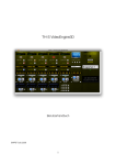
6.3. The Welcome display
When the analyzer is switched on, the welcome screen is displayed. If it does not, first check the backlight settings
(see section 6.1.2 on the previous page).
This screen provides information about ISL and two menus offering the choice of language (when this choice has not
been set as one of the Analyzer’s internal parameters).
I
S
L
Zi Verson
14790 VERSON
FRANCE
www.isl-france.com
Tel:02 31 26 43 00
Fax:02 31 26 62 93
English
Français
Figure 2: Welcome display.
This display remains active until the key corresponding to the language of your choice is pressed. Doing this
activates the display 1 of the FZP Pt Run/Start menu (see Diagram 1 page 2-27).
•Press the key corresponding to the language of your choice to continue.
Note: You can disable the language choice as part of the startup parameters, refer to the Part 3 section 7.1 page 351. If the choice is locked, press any key on the front panel.
DOCV226A011-C
FZP 5G2s User's Manual
Page 1-23
Page intentionally blank.
Page 1-24
FZP 5G2s User's Manual
DOCV226A011-C
Part 2 Use of the FZP 5G2s with preinstalled products
Page intentionally blank.
Page 2-26
FZP 5G2s User's Manual
DOCV226A011-C
Introduction
1.Introduction
This part will be concerned with all aspects relating to the test for determining the freezing point of hydrocarbons
using pre-installed products. They are stored in a memory that can be saved or updated very easily (e.g. when a
standard is changed) by downloading from a PC via the SERVICE port (refer to the chapter 0 page 4-66).
2.The first test
In this chapter we will deal with a Freezing point test carried out with the FZP 5G2s, stage by stage. We will,
however, only describe the menus that are strictly necessary for the successful operation of the test, the main screen
level being explained in Part 3. We will further assume that the operator has taken due note of the care that needs to
be taken with the substances tested.
I
S
L
www.isl-france.com
Tel:(33) 2 31 26 43 00
Fax:(33) 2 31 26 62 93
Français
ZI Verson
14790 VERSON
FRANCE
English
FZP Pt Run/Start menu
Prod: 1 By default
ID:
Op:
Product
Smpl ID
Oper.
Start
now
Select a product
1
2
3
4
5
: By default
:
:
:
:
6 :
7 :
8 :
9 :
10 :
Sample ID
Other
OK
_
ABCDEFGHIJKLMNOPQRSTUVWXYZ °#&\|@[]^~:
A
abcdefghijklmnopqrstuvwxyz +*/=<>()’"%
Select an operator name:
Insert
OK
Suppr.
1
2
3
4
5
:
:
:
:
:
6 :
7 :
8 :
9 :
10 :
OK
Other
FZP Pt Run/Display screen
Prod: 1 By default
Status: Cooling
24/01/2003 14:12
ID:
26.0° C
Diagram 1: Starting a test.
DOCV226A011-C
FZP 5G2s User's Manual
Page 2-27
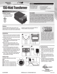
When the device is switched on, the welcome display (see Figure 2 page 1-23) appears. After the language has
been selected (or any key pressed if the language has been locked), the FZP Pt Run/Start menu display directly
appears thus (refer to the Diagram 1 on the previous page):
Prod: 1 By default
ID:
Op:
Product
Smpl ID
Oper.
Start
now
Figure 3: Screen of the FZP pt. Run/Start menu
There are two points to be made in this respect :
After switching on the device, the display of the FZP pt Run/Start menu above is obtained after the
language has been chosen or by pressing any key on the front panel if the language has been locked.
This screen is not placed hierarchically after the Welcome display. The arrow on the left bottom of
the display, the PREVIOUS DISPLAY key (see in section 6.1.1 page 1-22), allows backing up on the main
screens level (refer to the Part 3 chapter 2 - The main level screens page 3-35).
These measures have been taken to accelerate access to test-related menus.
The FZP Pt Run/Start menu display contains the following information:
•Prod: type of product tested (selected by default at switching on)
•ID: identifying name of the sample
•Op: identifying name of the operator
The FZP Pt Run/Start menu display contains the following menus and buttons:
Product : selection of the product type (and its associated run parameters) used to carry out the test
Smpl ID: sample identifying name entry button
Oper. : operator name entry button.
Start now : Start test button.
Note: All these information are optional to start a Freezing point determination test.
Actually if the product selected by default at switching on is suitable for the specimen to be tested, just start the test
by pressing the Start now button.
Page 2-28
FZP 5G2s User's Manual
DOCV226A011-C
The first test
2.1. Selection of a pre-installed product
The Product menu of the FZP Pt Run/Start display (see Figure 3 on the previous page) enables the factory preinstalled product list to be displayed in order to select a product other than one selected by default at switching on.
Different parameters (defined in the Run Environment menu, refer to the Part 3 chapter 5 page 3-43) are
associated with each of these products. Activating the Product menu displays the screen below:
Select a product
1
2
3
4
5
: By default
:
:
:
:
6 :
7 :
8 :
9 :
10:
Other
OK
Figure 4: Product list display of the FZP pt. Run/Start menu
The FZP 5G2s Analyzer can store up to 40 prestored products; the black arrow in the top right-hand corner of the
screen indicates the presence of more lists following on. Use the RIGHT and LEFT DIRECTION KEYS to move from table
to table and scroll through the different pages of products.
To select a prestored product, enable the corresponding field with the DIRECTION KEYS. When the desired field has
been enabled, press the OK key to confirm the selection and return automatically to the FZP Pt Run/Start menu.
The Other menu lets you create a new product to configure a test without using a prestored product but this new
product will not be stored in the list of prestored products (this operation requires level 1, Laboratory level, authorized
access). This method is therefore recommended for one-off tests only.
Press the OTHER key. The screen 1 of the product Environment menu is displayed allowing configuring all
parameters of a product. Refer to the Part 3 chapter 5 - Test setting and printing: the “Run Environment” menu page
3-43 for the procedure to follow.
2.2. Characterization of the test
2.2.1. Sample identifying
Press the Sampl ID key of the FZP Pt Run/Start menu (see Figure 3 page 2-28) to complete the information
regarding the sample identifying, the “Sample ID” entry screen is displayed. Enter the sample identification name
according to the procedure explained in the section below (see section 2.2.3 on the next page).
After confirming the sample ID by pressing the OK key, the initial screen returns automatically to the FZP Pt
Run/Start menu.
2.2.2. Operator ID
Press the Operator key of the FZP Pt Run/Start menu (see Figure 3 page 2-28) to complete the information
regarding the operator identifying. A list of operator names is displayed:
Select an operator name:
1
2
3
4
5
: FK
: HL
:
:
:
6 :
7 :
8 :
9 :
10 :
OK
Other
Figure 5: List of operator names
The FZP 5G2s can store up to 10 operator names. If the desired name has already been saved, enable the
corresponding field with the DIRECTION KEYS on the front panel, and then press OK, the initial screen returns
automatically to the FZP Pt Run/Start menu.
The Other menu lets you identify a new operator, but not record the new identifying name in the list of prestored
names (this operation requires level 1 (Laboratory level) authorized access). This method is therefore recommended
for one-off tests only. To create a new name and save it to memory, see Part 3 chapter 5 - Test setting and printing:
the “Run Environment” menu page 3-43.
Select a name or select an empty field then press the OTHER key to display the “Operator name” text entry screen.
Enter the operator name according to the procedure described below (see section 2.2.3 on the next page). After
confirming the operator ID by pressing the OK key, the initial screen returns automatically to the FZP Pt Run/Start
menu.
DOCV226A011-C
FZP 5G2s User's Manual
Page 2-29
2.2.3. Text entry display
2.2.3.1. Text entry
On this screen, the sample-identifying name for example can be entered. Values for the fields offered can be entered
by means of the corresponding buttons. Thus, to enter the sample-identifying name, the Smpl ID button of the FZP
Pt Run/Start display is pressed. The following display then appears:
Sample ID
_
ABCDEFGHIJKLMNOPQRSTUVWXYZ °#&\|@[]^~:
abcdefghijklmnopqrstuvwxyz +*/=<>()’"%
OK
Delete
Insert
Figure 6: Text entry screen. The field concerned is the sample-identifying name (sample ID).
This display is typical of text entry displays. It is found at all points and is essentially made up of two parts:
A variable part, on the upper part of the display, which is the name of the field.
A recurrent part (whatever the field is) consisting of an alphabetic table (from which the characters to be entered
are selected) and three buttons: OK, DELETE and INSERT.
The characters are entered in the following way:
1.On the entry display, a black rectangle flashes on the first letter of the table ("A"). To select a letter, use the
direction keys on the front panel. Press the key as often as necessary (or keep the finger pressed on it) to
indicate the direction of the character sought.
2.When the flashing rectangle is positioned on the character sought, press the ENTER key on the NUMERIC KEYPAD.
If the character is incorrect, cancel it with the CANCEL key.
3.If there is a mistake in the string of characters entered, use the DIRECTION KEYS and the Insert and Delete
buttons to remedy it.
4.Finally, validate with the OK button of the text entry display.
Proceed in similar fashion for the operator name.
Note: To speed up the test run procedure, the text entry screen has a semi-automatic input
feature.
After validating the initial display returns automatically (in this case, to the FZP Pt Run/Start menu). The same is
true at each entry of text variables by means of the text entry display.
2.2.3.2. Assisted edition
To speed up test starting the text entry screen enjoys a semi-automatic input feature: the latest text inputs are stored
in memory so that the operator only needs to enter the first two or three characters for the whole to be displayed.
If the function Auto Edition is activated, the Analyzer proposes a suite when characters are entered according to
prior enters. This function is intended for accelerate test initiating and it can be configured or deactivated (refer to the
section 7.1- Power on parameters: the "General" menu page 3-51).
Page 2-30
FZP 5G2s User's Manual
DOCV226A011-C
The first test
2.3. Initiating the test
2.3.1. Procedure
After having prepared the analyzer, carry out the following operations to initiate a freezing point test:
Do not forget to put the beaker under the drain tube in order to recover the used sample (see Picture 5
page 1-21).
1.Withdraw, by means of the syringe provided, a 10-ml volume of the sample (for a justification of this choice of
volume, refer to the chapter 5 - Description of the device page 1-21).
2.Insert syringe gently into the orifice designed for this purpose on the test bench (see Picture 4 on page 1-21) and
inject the contents of the syringe.
After the sample is injected, it is essential that the syringe remains inserted in the sample injection orifice.
3.Activate the Start now menu of the FZP Pt Run/Start menu (see Figure 3 page 2-28) : if all the stages have
been carried out correctly, the test starts and the following display will appear:
Prod: 1 By default
Status: Cooling
ID:
26.0°C
24/10/2002 14:12
Figure 7: Start now display (in cooling phase)
The display contains the following information:
•Prod: product type selected to carry out the test
•ID: identifying name of sample
•Status: indicates the operation in progress; in the case of the above figure, this is the cooling phase for the
sample. The indication
Freeze in the status field characterizes the hydrocarbon freezing point search phase.
•The current date and time.
•The current sample temperature given by the sensor (in bold characters).
2.3.2. Test in progress
The FZP 5G2s will cool the sample down until hydrocarbon crystals appear. When the optical detection cell detects
the sample is dark the cooling phase stops. The FZP 5G2s then starts to search for crystals disappearance point by
heating the sample at a low rate.
When the point at which the crystals disappear has been found the message “FREEZE Pt” appears and the result is
displayed.
Then the final phase of sample reheating starts: the analyzer begins a faster warming up of the sample to reach the
ambient temperature, thus allowing a new test to be begun rapidly.
ID:
FREEZE Pt:
24/10/2002 14:12
--54.1°C
Samp.Tmp: 18°C
Figure 8: End of test display (in reheating phase)
To achieve a greater reliability in the result, the FZP 5G2s continues for a moment to heat the sample at a
low rate after finding the point at which the crystals disappear to satisfy itself that the point of
disappearance of the crystals is indeed that found previously. This being so, the sample temperature
display (Figure 7) "jumps" to the End of test display (Figure 8).
DOCV226A011-C
FZP 5G2s User's Manual
Page 2-31
The rapid warming up phase is indicated by the flashing of the green LED of the Stop/Test key (please refer to the
section 6.2 page 1-23).
The result is displayed in reverse video. It is stored in the memory (refer to the chapter 3 - Results displaying and
printing: The "Results" menu page 3-37 for the description of information supplied).
2.3.3. End of test
The end of the test will be indicated by a warning alarm when the sample temperature has attained about 12°C:
1.The message “End of test: Freeze point detected” indicates the Freeze point of the sample tested is obtained.
The result is displayed and stored in the analyzer memory device.
2.The message “End of test: Freeze Pt not detected” indicates the point at which the crystals disappear has not
been found. The FZP does not store any temperature (the result display will not be displayed) but the result is
nevertheless registered.
3.The message “End of test: Crystall. not detected” indicates that no crystallization had been detected (Cd, see
Diagram 4 page 3-39) before the lower temperature set in the product run parameters is reached. Then the
Analyzer can not search the point of crystals disappearance but the result is nevertheless registered.
Press the ALARM STOP key on the keypad to display the alarm message and to acquit it. These messages will be
stored with the results in the memory device.
In few rare cases the FZP 5G2s can start a confirmation cycle so as to improve the result accuracy. The indication
“Second cycle” then appears on the Start now display replacing the sample temperature field (see Figure 7 page 231). Then the test can last up to 30 min. This will be signaled by a message on the result curve and by a binary
message on the result ticket (refer to the section 3.2 page 3-40).
The personalization of the parameters, together with the display and printing out of test results, will be dealt with in
the second part of this manual.
2.4. Cleaning the detection cell
Cell cleaning is normally done with the next sample and a chase-n-flush technique. It will be recalled, however, that
the sample volume has been so calculated that the cell is cleaned by it. But the detection cell will have to be cleaned
from time to time or after running dirty samples or heavily contaminated jet fuel samples. For this, inject 10 ml of
heptane (do not forget to put a beaker at the appended tube end).
Caution! Do not use acetone.
All solvents are prohibited (they may cause deterioration of the cell). Use only heptane.
Note: If the cell is accidentally cleaned with a solvent, this will be rapidly rinsed with an injection from 10 to 20 ml of
heptane or kerosene.
Page 2-32
FZP 5G2s User's Manual
DOCV226A011-C
Part 3
Advanced use of
the FZP 5G2s
Page intentionally blank.
Page 3-34
FZP 5G2s User's Manual
DOCV226A011-C
Introduction
1.Introduction
This part deals with the advanced use of the FZP 5G2s, i.e. the setting of the device according to the needs of the
user. As previously indicated, this presupposes that the user is familiar with the techniques of plugging tests.
The FZP 5G2s settings are accessible from the main screens level (see the Diagram 2 bellow).
2.The main level screens
I
S
L
Zi Verson
14790 VERSON
FRANCE
English
FZP 5G2s
S/N: 214
FZP 5G2s
Software V w.x (Detection y.z)
FREEZE Pt.Run
Start
Display Results
www.isl-france.com
Tel:02 31 26 43 00
Fax:02 31 26 62 93
Français
S/N: 214
Software V w.x (Detection y.z)
Access
Print
Run env
Service
FZP 5G2s
S/N: 214
Software V w.x (Detection y.z)
Quality
Setup
Main screens level
FZP Pt Run/Start
menu
Prod: 1 By default
ID:
Op:
Product
Smpl ID
Oper.
Start
now
Diagram 2: Access to the main display level.
The main level display is the highest hierarchically speaking. It is not directly accessible when the unit is switched
on.
To access it, after switching on the unit and selecting a language (or pressing any key if the language has been
locked), it is necessary to go up one display level (press the RETURN ONE LEVEL UP button, see in Part 1 section 6.1.1
page 1-22).
The Diagram 2 above shows how access to this level operates (refer to the Appendix C page 85 for a complete view
of menus functionality).
If the user has operator level access (access 0), a simple menu is available (
):
A test can be started and followed.
A result and result details can be displayed and printed.
Users with laboratory (access 1) or service (access 2) level access have a complete menu (
DOCV226A011-C
FZP 5G2s User's Manual
+
+
).
Page 3-35
FZP 5G2s
S/N: 214
Software V w.x (Detection Vy.z
FREEZE Pt.Run
Start
Display
Results
Access
FZP 5G2s
S/N: 214
Software V w.x (Detection Vy.z)
Print
Run Env
Service
Quality
FZP 5G2s
S/N: 214
Software V w.x (Detection Vy.z)
Setup
Figure 9: The three displays of the main menu.
The main display level includes the following components, respectively from top to bottom and from left to right:
•The name of the device.
•The serial number of the device.
•The version of the control software and the version of the detection cell.
The menus of the main level are FZP Pt. Run/Start, FZP Pt. Run/Display, Results, Access, Print, Run
Environment, Service, Quality and Setup. These menus will be dealt with in detail in the paragraphs following.
It should be noted, however, that the FZP Pt Run (Start and Display) menu was covered almost in its entirety in
Part 2.
In the following we shall assume that the access level is level 1 (Laboratory). This level allows access to the settings
associated with tests, making it possible to modify them and thus design personalized products that respond to
specific needs. The access levels will be dealt with through the Setup menu.
Page 3-36
FZP 5G2s User's Manual
DOCV226A011-C
Results displaying and printing: The "Results" menu
3.Results displaying and printing: The "Results" menu
Main level screens
FZP 5G2s
S/N: 214
Software V w.x (Detection y.z)
FREEZE Pt.Run
Start
Display
Results
FZP 5G2s
S/N: 214
Software V w.x (Detection y.z)
Access
Print
Run env
Service
FZP 5G2s
S/N: 214
Software V w.x (Detection y.z)
Quality
Setup
Results
Res. : 26/52
29/12/2003 15:26
Prod: 1JET (°C)
ID: 25732IH4
Freeze point : -34.2°C
Print
Transm.
Details
Diagram 3: The Results menu
Test results are stored in a dedicated memory. The FZP 5G2s can store between 45 and 50 test results. When the
memory is full, the FZP 5G2s automatically overwrites the first results recorded.
Results can be displayed, printed and sent to a PC by the RS232C link (refer to the Part 1 section 4.3.3 - FZP 5G2s /
PC link page 1-19).
3.1. Result displaying from result memory
From the Freeze Pt Run/Start menu the user must go up one level in the display hierarchy: press the arrow key on
the left bottom of the display, the PREVIOUS DISPLAY key (see in Part 1 section 6.1.1 page 1-22) to return on the main
screens level (see Diagram 2) then:
1.Press the button for the Results menu of the main level screen 1; this calls up the display allowing access to all
the results saved, which are shown as the display below (Figure 10).
2.To access the desired result, press the DIRECTION KEYS as many times as needed.
Note: The black arrow at the left bottom of the screen indicates the presence of a registered result after the result
displayed.
*Res. : 36/52
05/01/2004 10:11
Prod: 1 Jet A1
ID: Jet A1
Freezing point: -50.5°C
Print
Transm.
Details
Figure 10: Display of the Results menu.
This screen contains the following indications:
•Res. : __/__: Number of the result displayed over the number of results stored in memory
* : an asterisk appears in front of the result number if the test was run although a default had been notified or if a
default occurred during the test. These defaults are not displayed but they are printed out with the result in the
form of a binary message (refer to the next section).
•Date and time of the end of the test.
•Prod : name of the product profile use to test the sample
•ID : Identifying name of the sample
•Freezing point: _ _: Temperature of the point at which crystals in the sample disappear and the cause for test
termination.
2 other possible causes for termination can be displayed:
Freezing point not detected
Crystal. Not detected till _ _
The different types of test have been dealt in the section 2.3.3 - End of test page 2-32.
The end of a test triggers a warning alarm peculiar to each type of end of test. Refer to the section 6.5 page 3-48
for more precise details about these alarm messages.
DOCV226A011-C
FZP 5G2s User's Manual
Page 3-37
The result display contains the following menus and button:
Print: To print the result selected (displayed) and to access to the printer setup menu – see next section
Transm.: Press the Transmit button to validate the result displayed and send it through the serial RS 232C link.
Parameters linked to this communication mode have to be set (refer to the section 7.6.1 page 3-53). Messages
are transmitted in the form of character string in ASCII code (refer to the Appendix B for the meaning of the
content of the messages).
Details: To display the result detail display:
*Res. : 36/52
05/01/2004 10:11
Prod: 1 Jet A1
ID: JET A1
Freezing point: -50.5°C
Cd:-54.1°C Co:-55.6°C Do:-50.6°C
Figure 11: The Result Details display
This screen contains in the upper part the same indications as the display of the Results menu and in the lower part,
3 additional values that characterize the tested fuels’ cooling behavior: Cd, Co, and Do resulting from the two signals
supplied by the optical detection cell (see the following diagrams):
•the Detection signal allowing to determine crystals presence
•the Opacity signal allowing to indicate the sample opacity
Therefore, crystal appearance and disappearance in fuel sample causes typically two peaks in the FZP 5G2s’
Detection Signal; its amplitude and width depend on size and shape of crystals as well as freezing rate of a
particular jet fuel. Neat jet fuels typically show narrow, sharp curves (see Diagram 4 below), while contaminated
fuels’ curve shape can vary widely as their inherent multi-stage crystallization process generates a complex
response curve formation (see Diagram 5 below).
Like Detection Signal, the form and amplitude of the Opacity Signal curve depend on crystal size and shape as well
as the freezing rate of a particular jet fuel. But generally speaking, crystals appearance and disappearance are frank.
Freezing point is the temperature at which last crystals disappear during the reheating stage, this value is
determined by the detection signal.
Cd is the temperature at which the first crystal appears. This value is determined by the detection signal.
Co is the temperature at which the sample becomes dark.
In Neat Fuels, crystals apparition is very frank and the sample becomes nearly immediately dark. Cd is almost
the same as Co.
In Contaminated Samples, Cd is detected much earlier as typically crystals of contaminant appear first. At low
levels of contamination, concentration of such crystals is not sufficient for generation enough light for reliable
Co determination. Co will be detected when crystalline structure starts to be formed which correspond to
beginning of aviation fuel crystallization (the sample becomes dark).
Do is the temperature at which dark almost completely disappears (detected by the Opacity signal).
In Neat Fuels, Do is almost the same as Freezing point.
In Contaminated Samples, Do responds only when the general mass of crystals has disappeared. Due to still
retained crystals of contaminant, the real Freezing point, according to method, is significantly warmer than the
less sensitive Do reading. Nevertheless, at low levels of contamination, Do value can give obvious idea what
might be the Freezing point of aviation fuel if it were not contaminated.
Printout of this additional information on the result ticket or on the result curve is disabled in factory-delivered FZP
5G2s units; however, an experienced user can enable these functions in the field (refer to the section 4.2- Printer
setup page 3-41).
It’s important to note that this additional information (Cd, Co, Do) is exclusive to ISL’s FZP 5G2s design and
detection technique and should be interpreted and applied by users at their own discretion.
These values are derived from a physical property of tested fuel and are therefore repeatable and reproducible;
however, repeatability and reproducibility have not been defined. ISL does not warranty correlation of these
additional values to any known test method. ISL, however, does guarantee reliable Freezing point value from the
FZP 5G2s.
Page 3-38
FZP 5G2s User's Manual
DOCV226A011-C
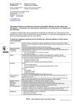
Results displaying and printing: The "Results" menu
ISL FZP 5G2s
S/N : 214
Date : 05/01/2004
10 :11
Product : 1 Jet A1
V5.4
12/01/2004
Op : HC
ID : Jet A1
Freezing point : -50,5°C
D e te c t i o n V 5 . 3
Cd : -54.1°C
Do : -50.6°C
Co : -55.6°C
*1/1*
Co
Do/Freezing Pt
Cd
Diagram 4: Result curve of a neat sample
ISL FZP 5G2s
S/N : 214
Date : 05/01/2003
10 :37
Product : 1 Jet A1
V5.4
12/01/2004
Op : HC
I D : + 2% G o
Freezing point : -37,0°C
D e te c t i o n V 5 . 3
Cd : -47.3°C
Do : -50.8°C
Co
Co : -53.5°C
*1/1*
Do
Freezing Pt
Cd
Diagram 5: Result curve of a contaminated sample
DOCV226A011-C
FZP 5G2s User's Manual
Page 3-39
Information printed with the result curve:
In the top left:
•The analyzer type, its serial number, the N° of the software version installed, the date of the current day
•The date at which the test has been performed, the hour of the test end and the name of the operator
•The product name and the sample identifying name
In the top right:
•The result message “Freezing point: -_ _ . _ “: temperature at which the crystals disappear in the sample
•If this result is rounded (at 0,5°C/°F), the indication “Rounded” appears under the result (parameter of the product,
refer to the section 5.1 page 3-44)
In the middle right:
•The value of parameters Cd, Co and Do
•The indication *1/1*: Number of cooling cycle performed / N° of the cycle having allowed to detect the Freezing
point (up to 2 cycles).
3.2. Result printing
The FZP 5G2s can print results in different ways: with or without details values, with or without product parameters,
in ticket or in curve form. The data printed depend on the analyzer setup and, as required, the results of the last test
or of any test (refer to Appendix A page 71 for printing type examples).
It is also possible to print test results automatically after the end of the test (refer to the section 4.2- Printer setup
page 3-41). To be able to do this, make sure that the unit is linked up to a printer compatible with the analyzer (using
PCL-3 or ESP/P language) and set “on line”.
From the display of the Results menu (Figure 10 page 3-37) press the Print key, the following display appears:
Results printing
Start printing
Now
Print
Content
Printer
Stop
Figure 12: Print menu display (of the Results menu)
This display contains the following menus and buttons:
•Start printing Now: To start the printing of the selected result according to the printer setup.
•Print content: To define the data to be printed and to set the printer.
Pressing the Print Content button calls up the Setup menu of the Print menu. Refer to the section 4.2 - Printer
setup page 3-41. Modify the printer setup requires having level 1 access authorization.
•Printer Stop: To stop the current printing.
Information like warnings occurred during a test just appears at result ticket printing. These failures, indicated at
result displaying by an asterisk in front of the result number (see the Figure 11 page 3-38) are identified by a binary
message printed with the result at the bottom of the ticket or on the curve in the top left following the information:
Warning during test:
Displaying of bits in the following order: bit 7, 6, 5, 4, 3, 2, 1, and 0
Bit
0
1
2
3
4
5
6
7
Significance
Bit 0 = 1: Adjustment of the temperature measurement circuit have to be done
Not used
Not used
Not used
4 = 1: Test performed with two cooling cycles
Not used
Not used
Not used
Note: When only the condition “2 cooling cycles” occurs, the warning binary message is not indicated on the curve
because the message: “As dual cooling cycle was done.
Opacity signal is not available”
is clearly printed in the bottom right of the curve.
Page 3-40
FZP 5G2s User's Manual
DOCV226A011-C
Printing and printer setup: The “Print” menu
4.Printing and printer setup: The “Print” menu
Main level screens
FZP 5G2s
S/N: 214
Software V w.x (Detection Vy.z)
FREEZE Pt.Run
Start
Display
Results
FZP 5G2s
S/N: 214
Software V w.x (Detection Vy.z)
Access
Print
Run env Service
Quality
FZP 5G2s
S/N: 214
Software V w.x (Detection Vy.z)
Setup
Print
Printing
Service
Setup
Stop
Diagram 6: The Print menu
To access to the printing menu, activate the main level Print menu; the following display will appear (as the Diagram
6 above describes it):
Printing
Service Setup
Stop
Figure 13: Print menu screen
The Print menu screen contains the following menus and commands:
•Service : To print the values of measurements and internal parameters (level 2 access required)
•Setup : To setup printing parameters
•Stop : To stop the current printing job
4.1. Service printing
The Service menu of the Print menu is designed for Analyzer maintenance and requires Level 2 access. It contains
submenus from which internal Analyzer measurements can be printed, either instantly or during a full test run
(monitoring regulation) or also the internal Analyzer parameters. Refer to the Part 4 chapter 3 - The “Service” menu
of the main printing menu page 4-64.
4.2. Printer setup
The printer is configured by means of the Setup button of the Printer menu (see Diagram 6 above). Configuration
can also be carried out by means of the Printer menu of the Setup menu (screen 3 of the main screens level).
The following screens appear:
DOCV226A011-C
FZP 5G2s User's Manual
Page 3-41
Display
Meaning of different menus
(Print menu of the Setup menu).
(Going from left to right and from top to bottom).
Field values
Next display
Printer setup
Results printing configuration
Yes
Auto
Curve
Complet
Format
Content
Printer
Check
Auto : automatic printing at the end of test
Yes/No
Format : printing format
Curve/Ticket
Content : printing content
Detailed/Light
Printer check : starting of the printer test
Setup menu display 1
When the content is “detailed”, the detailed values (Cd, Co and Do, refer to the section 3.1 page 3-37) are printed with the
result (ticket or curve) and parameters of the product profile used to carry out the test are printed on the result ticket.
Printer setup
Deskjet color
18
248
Form Feed
Printer
Select
Red
code
Degree
code
Line
feeds
Printer select : printer selection compatible Epson compatible
with the Analyzer (using PCL3 or ESC/P ESC/P; 40
columns; DeskJet
language)
Black/White;
DeskJet Color
Red code: code for printing in red (see printer See printer doc.
doc.).
Setup menu display 2
Degree code: ASCII code designating "degree" See printer doc.
code (see printer doc.).
Line feeds: number of line feeds after printing.
0 to 5
4 printer types can be selected:
E.g. :
Configuration of a 40 column CITIZEN® printer
40
18
91
2
Configuration of an ESC/P 80 column printer
ESC/P
248
2
Configuration of a DeskJet® Color printer:
DeskJet 18
248
Form Feed
Color
For the exact configuration, however, reference must be made to the manual supplied by the printer manufacturer.
Table 1: Print / Setup menu display
Page 3-42
FZP 5G2s User's Manual
DOCV226A011-C
Test setting and printing: the “Run Environment” menu
5.Test setting and printing: the “Run Environment” menu
Main level screens
FZP 5G2s
S/N: 214
Software V w.x (Detection Vy.z)
FREEZE Pt.Run
Start
Display
Results
FZP 5G2s
S/N: 214
Software V w.x (Detection Vy.z)
Access
Print
Run env
Service
FZP 5G2s
S/N: 214
Software V w.x (Detection Vy.z)
Quality
Setup
Run env
Run environment programming
Product
Oper.
Diagram 7: The Run Environment menu
All run parameters of a product profile are visible but a product can only be created or modified if one has the level 1
access authorization (Laboratory).
Access to the run parameters of a product profile as follows:
1.Enable the Run Environment menu on screen 2 of the main level screens (see Diagram 7 above). The
following screen is displayed:
Run environment programming
Product
Oper.
Figure 14: Run Environment menu screen
The Run Environment menu screen contains the following menus:
Product : to display the prestored products list to print, modify or create of a new product profile
Oper. : to display the operator names list to print, modify or create a new operator ID.
Values in the fields of the Run Environ. menu screen cannot be changed without level 1 access
(password), Laboratory.
DOCV226A011-C
FZP 5G2s User's Manual
Page 3-43
5.1. Run parameters of a product
Press the Product key in the Run Environment menu to display the list of prestored products, the following screen
is displayed:
Select a product:
1
2
3
4
5
:
:
:
:
:
6 :
7 :
8 :
9 :
10:
Details
Print
Figure 15: Product menu screen
The Product menu screen contains the following menus:
Print : to print run parameters of the product selected
The Print menu lets you print out the run parameters for the product selected. Press the Print key to start printing
immediately. See the printout example in Appendix A section 2 - Product parameter print page appendix 73.
Details : to access to the product setup menu (see table below)
The FZP 5G2s Analyzer can store up to 40 prestored products; the black arrow in the top right-hand corner of the
screen indicates the presence of more lists following on. Use the RIGHT and LEFT DIRECTION KEYS to move from table
to table and scroll through the different pages of products.
Select a prestored product if you wish to modify its associated run parameters or select an empty field if you wish to
create a new product (see in Part 2 section 2.1- Selection of a pre-installed product page 2-29 for precise
explanations on how to select a field). Press the Details key, screen 1 of the product Details menu is displayed as
shown in the table below.
Display
Meaning of different menus
(Product details menu).
(Going from left to right and from top to
bottom).
Field values
Current product is N°1
Product No: 1
JET (°C)
Name
°C
Unit
Product details menu display 1
Name: product name entry button. String
The product name in this case is JET
Unit: selection of temperature °C/°F
measurement unit. The temperature
is here measured in °C.
Next display...
Results Rounded: the results can be YES/NO
rounded to the nearest 0.5°C.
Product No: 1
Stop Tmp. : temperature of the end
of the cooling phase.
Min :-1200°C
–
184°F
Max :+10°C – 50°F
NO
-100°C
Results
Stop
Rounded
Tmp
Product details menu display 2
Table 2: Product details menu displays
Without the necessary authorizations (passwords), it is not possible to change the field values of the
Product menu displays. This requires authorization at Access 1 level.
Page 3-44
FZP 5G2s User's Manual
DOCV226A011-C
Test setting and printing: the “Run Environment” menu
5.2. List of operator names
Press the Operators key in the Run Environment menu to display the prestored list of operator names (up to 10),
the following screen is displayed:
Select an operator name:
1
2
3
4
5
: ML
: LG
: LL
:
:
6 :
7 :
8 :
9 :
10:
Details
Print
Figure 16: List of operator names
The Product menu screen contains the following menus:
Print : to print the list of operator names
Details : to enter a new name or modify the name selected
The Print menu lets you print out the complete list of operator names. Press the Print key to start printing
immediately. See the sample printout in Appendix A section 3 - Operator name list page appendix 73.
Select a prestored operator name if you wish to modify it or select an empty field if you wish to create a new operator
name. Press the Details key, the « Operator » text entry screen is displayed. Enter the name (see in section 2.2.3
page 2-30 for further details on using the text entry screen) then press OK to confirm.
DOCV226A011-C
FZP 5G2s User's Manual
Page 3-45
6.Alarm treatment
6.1. Types of alarm
6.1.1. Failure alarms
The failure alarms warn the operator in the event of a malfunction.
Failure alarm detection has at least one of the following consequences:
•A test cannot be started,
•A test in progress is stopped,
These failures set off a continuous audio alarm and the red LED of the ALARM STOP key lights up on the keypad (see
in section 6.2 page 1-23). Press the ALARM STOP key to display the alarm message and acknowledge it or not.
The red LED stays on for as long as the failure persists, even if the alarm has been acknowledged.
6.1.2. Warning alarms
The warning alarms warn the operator of an expected event: “End of test: Freezing point detected” for example.
They are accompanied as for them by a discontinuous audio alarm (the signal modulation width is adjustable; refer
to the section 7.3 page 3-51 of this part). The red LED on the ALARM STOP key lights up on the keypad. It goes off
when the alarm is acknowledged.
6.2. Displaying alarms, stopping the buzzer
When an alarm is triggered, press the ALARM STOP key to display the cause. The following screen is displayed:
No alarm to signal
Exit
Acquit
Review
Figure 17: Alarms displaying screen
The alarms screen display contains the following menus and buttons:
Exit: to go back to the previous screen without acquitting the alarm.
Acquit.: to acquit the alarm and to go back to the previous screen.
Press the Acquit key to stop the buzzer and return to the previous screen. Note that the red LED on the ALARM
STOP key stays on for as long as the default persists, even if the alarm has been acknowledged.
Review: to display the alarm historical.
6.3. Alarm processing
Certain alarm cases present a danger. This is why most default settings switch the Analyzer into idle status, thus the
cooling unit is cut out and the heating is stopped.
However, this is not to say that this type of analyzer is hazard-free or that if the Analyzer fails to go into idle status
the operator and/or Analyzer are not in danger. It is important always to check what is going on whenever an alarm
is triggered.
Attention! Generally when the alarm buzzer is triggered, the operator must display the cause and
ensure that everything is working correctly.
For example, owing to a faulty component an alarm that normally should place the analyzer in idle mode fails to do
so. In that case, the operator must intervene by switching off the Analyzer.
Page 3-46
FZP 5G2s User's Manual
DOCV226A011-C
Alarm treatment
6.4. Failure alarms
6.4.1. Memory failure
When the analyzer is switched on, the microprocessor checks the content of the different memories. If there is an
error it will be detected by calculation and comparison with the checksum.
6.4.1.1. “Software memory (PROM)” failure
If this failure is reported, switch the analyzer off then on again. If the failure persists, contact the ISL Customer
Service.
6.4.1.2. “Data memory (Ram)” failure
If this failure is reported, switch the analyzer off then on again. If the failure persists, contact the ISL Customer
Service.
6.4.1.3. “Safe memory (NVM)” failure
The battery for backing up the non-volatile back-up memory (NVRAM) has a service life of 7 to 8 years. This alarm
may therefore be due to a faulty battery.
The content of the saved RAM memory where the Analyzer parameters are stored is checked by the
microprocessor. If there is an error, the Analyzer goes automatically into « download » mode so that the contents of
the RAM memory saved can be restored by loading a backup file from a PC.
For this purpose, a diskette containing the internal parameter factory settings (necessary if memory has not been
recently uploaded) and a PC up/download program are shipped with the standard version of the Analyzer. Refer to
the section 4.4 - File download command: the “ISL UDS" menu page 4-66 on how to load the Analyzer parameters.
Note: So as to have an up-to-date copy of the Analyzer’s internal parameters always to hand, it is advised
to upload the internal parameters to the PC during routine maintenance operations.
Use a new file name each time this operation is performed. Do not use the internal parameter file name on the
original diskette supplied with the Analyzer.
6.4.2. “Low battery”
The system keeps a permanent check on this failure. If the failure is reported:
Do not switch off the analyzer, as this will delete any stored data.
Print or upload to a PC file the Analyzer parameters contained in the non-volatile back-up memory (NVRAM):
Uploading: refer to the section 4.4 page 4-66 on how to load the back-up memory (internal parameters, setting
values, run environments and results).
Printing: the run environments (product run parameters, operator names list, see chapter 5 page 3-43) and the
internal parameters (refer to the chapter 3 page 4-64).
Switch off the Analyzer and call an ISL approved technician to replace the battery (refer to the Service Manual).
Download Analyzer internal parameters or enter it (refer to the chapter 3 - The “Service” menu of the main printing
menu page 4-64).
Note: Regular uploading of the internal parameters must be programmed as part of the analyzer
maintenance procedure. Use a new filename (e.g. with the current date in the name- PIDDMMYY. NVM).
This way the latest version of the internal parameters will be saved to a file.
6.4.3. “Signal conditioning (A/D Cnv)”
This failure is reported upon detection of no dialogue between the CPU and the A/D converter. Switch the analyzer
off then on again. If the failure persists, contact the ISL Customer Service.
6.4.4. “Cooling circuit”
The system checks the cooling circuit 5-min after test starting by verifying the cooling rate. The alarm is triggered if:
1 min after the test is started the rate is higher than threshold 2 (by default: -3°C/min, programmable from -2 to 5°C/min)
On cooling during opacity search:
if the rate is higher than threshold 1 (by default: -1°C/min, programmable from –1 to –10°C/min) during a
recognition time programmable from 0 to 120 s.
A test currently running is stopped. Alarm is stopped each time a test is run.
DOCV226A011-C
FZP 5G2s User's Manual
Page 3-47
6.4.5. “Heating circuit”
The system checks for this failure from the start of the test by verifying the heating rate. The alarm is triggered if it is
not sufficient.
The system cuts the heating command and stops a test being run. The alarm is stopped each time a test is run.
6.4.6. “Sample temperature safety”
The system checks for this failure during the entire test. The alarm is triggered if:
The sample temperature is higher than “threshold +“ (by default: 45°C programmable from –120 to +55°C) during
the recognition time (programmable from 0 to 120s).
The sample temperature is lower than “threshold-“ (by default: -120°C programmable from –120 to +55°C) during
the recognition time (programmable from 0 to 120s).
A test currently running is stopped. Alarm is stopped each time a test is run.
6.4.7. “Cooling unit temperature safety”
This alarm is triggered if the cooling unit is above 48°C. A test currently running is stopped.
In this case it is advised to:
Turn off the Analyzer
Clean the ventilation filters
Turn on the Analyzer
If the problem continues, contact ISL Customer Service.
6.4.8. “Cooling unit stroke control safety”
Contact ISL Customer Service.
6.4.9. “Cooling unit board link safety”
This alarm is triggered if no dialogue is detected with cooling unit control board. A test currently running is stopped.
Turn off the Analyzer.
Open the Analyzer and check the electronic boards connection (refer to the section 5.2 page 4-69)
Turn on the Analyzer
If the problem continues, contact ISL Customer Service.
6.5. Warning alarms
6.5.1. “End of test: Freeze point detected”
The normal Freezing point is obtained. The result is displayed and stored in the memory device.
The indication is displayed at the end of the test, i.e., when the sample has reached the ambient temperature.
The alarm is stopped each time a test is run.
6.5.2. “End of test: Freeze Pt not detected”
Detection temperature range was exceeded (temperature of the end of the cooling phase set in the product profile)
without the Freezing point being detected (the opacity temperature has been detected).
The FZP does not store any temperature (the result display will not be displayed, see section 2.3.2 page 2-31) but
the result is stored in the memory device. The alarm is triggered at the end of the test, i.e., when the sample has
reached the final temperature.
The alarm is stopped each time a test is run.
6.5.3. “End of test: Crystall. not detected”
The message “Crystallization not detected” indicates the sample temperature has exceeded the stop temperature
set in the test product and the opacity temperature has not been detected. Then the Analyzer could not search
crystals disappearance point.
Check on cooling during opacity search.
The result is stored in the memory device: Stop on stop temperature xx .x° .
The indication appears at the end of the test, i.e., when the sample has reached the final temperature. The alarm is
stopped each time a test is run.
Page 3-48
FZP 5G2s User's Manual
DOCV226A011-C
Alarm treatment
6.5.4. Buzzer modulation setup
Alarm displayed during the audio alarm test after modulation setting (refer to the section 7.3- Configuring alarms :
the "Alarm" menu page 3-51 of the current part).
6.6. Alarms historical
The FZP 5G2s can register up to 16 alarm messages.
Activate the Review menu from the alarm-displaying screen (see Figure 17 page 3-46), the following screens
appear:
Displays
Meaning of different menus
(Review menu of the Alarm displaying screen)
(Going from left to right and from top to bottom).
Faults review : permanent field
Exit: To go back to the alarms displaying screen
Print: To print the complete alarms review
Details: To display the detailed alarm message
Faults review
Date
Exit
Time
Message registered
Print
Field values
Details
Display 1 of the Review menu
Press the DETAILS key to access to the detail displaying screen of the alarm selected:
Next Display
Date:
Src:
Def:
Exit
Date: date at which the failure occurs
Src: state of the analyzer when the failure occurred ( idle,
run, diagnostic …)
Def: alarm message displayed
Exit: to go back to the alarm displaying screen
Details display the Review menu
Table 3: Screens of Review menu of the alarms displaying screen
DOCV226A011-C
FZP 5G2s User's Manual
Page 3-49
7.Configuration: the "Setup" menu
Main level screens
FZP 5G2s
S/N: 214
Software V w.x (Detection Vy.z)
FREEZE Pt.Run
Start
Display
Results
Access
FZP 5G2s
S/N: 214
Software V w.x (Detection Vy.z)
Print
Run env
Service
FZP 5G2s
S/N: 214
Software V w.x (Detection Vy.z)
Quality
Setup
Setup
FZP 5G2s
Analyzer setup
General
Run
S/N: 214
Alarms
Lab.
FZP 5G2s
Analyzer setup
Printer
RS232
S/N: 214
PC Link
FZP 5G2s
Analyzer setup
Clock
Service
ISL
S/N: 214
About FZP 5G2s
Diagram 8: Setup menu
The FZP 5G2s "working environment" can be completely configured. Thus the testing product in place when the
device is switched on can be re-set. The triggering or stopping of an alarm can also be set for when a given error
occurs and in other conditions set out below as RS 232C PC link and Alan® local network.
The configuration of the FZP 5G2s is carried out by means of the Setup main menu at the main display level (see
Diagram 8 above). After the Setup menu is activated the following displays appear:
FZP 5G2s
Analyzer setup
General
Run
S/N: 214
Alarms
FZP 5G2s
Analyzer setup
Printer
RS232
S/N: 214
PC Link
FZP 5G2s
Analyzer setup
Service
ISL
Labo
Clock
S/N: 214
About FZP
Figure 18: Displays of the Setup menu.
The above displays allow access to the configuration parameters set out below.
Page 3-50
FZP 5G2s User's Manual
DOCV226A011-C
Configuration: the "Setup" menu
7.1. Power on parameters: the "General" menu
The General menu allows choosing the access level and the language (if you would like to lock it) in place when the
device is switched on.
It also allows configuring (or deactivating) the assisted edition: the FZP 5G2s can proposes a suite to the characters
entered based on prior enters (refer to the section 2.2.3.2 page 2-30).
Displays
Meaning of different menus
(General menu of the Setup menu).
Field values
(Going from left to right and from top to bottom).
General setup (permanent field)
Power on parameters
Access level: choice of default access level
when the device is switched on.
General setup
At power on
0
Selection
2
Access Country
Auto
level
Langua Edition
0[3
: It should be noted that only the current
access level or lower access level could be
chosen.
General menu display
Country language: choice of language selected
by default (locked). “Selection” allows the
operator to choose the language.
Selection/Engli
sh/
Français
Auto Edition: characters number needed to
activate the auto edition (0 inhibits the function).
0
9
Press the ACCESS LEVEL key or the AUTO EDITION key then enter a value with the NUMERIC KEYPAD. Press the ENTER key
to confirm.
Press the LANGUAGE key to scroll through the various possibilities (flip-flop selection).
Table 4: General menu displays
7.2. Run parameters: the "Run" menu
The Run menu allows choosing the product profile in place when the device is switched on.
Displays
(Power on parameters. menu of the Setup menu).
Meaning of different menus
Field values
(Going from left to right and from top to bottom).
Run parameters (Permanent field)
Run parameters
Default Product: choice of the product profile
selected by default to carry out a test when
device is switched on (applied to a product type).
1: By default
Default
Product
1
40
Run menu display
Press the Default Product key, this calls up the product list. Select the product profile desired then press the OK key to
validate.
Table 5: Run parameters menu displays.
7.3. Configuring alarms : the "Alarm" menu
The Alarms menu allows thresholds of different alarms triggered in case of failure to be configured. This menu also
allows alarm buzzer modulation to be setup.
Activation of this menu calls up the following displays:
Displays
Meaning of different menus
(Alarms menu of the Setup menu).
Field values
(Going from left to right and from top to bottom).
Alarms setup
Buzzer
30%
OFF
Modulation
Test
Buzzer : permanent field
Modulation: to adjust the intermittence of discontinuous
alarm.
Test: to test the buzzer.
0
100
ON/OFF
Alarms menu display 1
Press the Modulation button to enter the new value (100%: continuous alarm - 0%: alarm mute).
Use the Test button to test the buzzer after modifying its modulation.
Next Display
DOCV226A011-C
FZP 5G2s User's Manual
Page 3-51
Alarms setup
Sample temperature safety
-125°C
45°C
10s
Thresh-
Thresh+
After
Alarms menu display 2
Sample temperature safety: permanent field
Thresh -: to enter the lower sample temperature the
system accepts (alarm triggered after a recognition time)
Thresh +: to enter the upper temperature safety the
system accepts (alarm triggered after a recognition time)
After: setting of the recognition time before upper
threshold to be taken account
-150°C
+55°C
-150°C
+55°C
0
120s
If the sample temperature exceeds limits values in the recognition time, here 10s, the system stops the test
immediately and the alarm message “Sample temperature safety” is displayed.
Next Display
Alarms setup
Cooling circuit
-1°C/min
120s
-3°C/min
Thresh1
After
Thresh2
Alarms menu display 3
Cooling circuit: permanent field
Thresh 1 : minimal cooling rate in opacity searching
phase
After : setting of the recognition time before the threshold
1 to be taken account
Thresh 2 : minimal cooling rate 45s after test starting
-1°C/min
-10°C/min
0à120s
-2°C/min
5°C/min
Next Display
Table 6: Alarm menu screens
7.4. Personalization and access authorization to level 1: the "Lab." menu
The FZP 5G2s can be personalized and so bear the name of the laboratory that acquires it, together with the name
of the head of the laboratory. He or she can restrict access to (write protect) certain parameters. The following
displays can be called up by activating the Lab. menu.
Displays
Meaning of different menus
(Lab. menu of the Setup menu).
(Going from left to right and from top to bottom).
Laboratory setup: permanent field
Laboratory setup
Access Code
Field values
Access Code: access code to level 1.
Up to 6
characters
Lab Name : name of laboratory using FZP 5G2s
String
Lab.name
Lab. menu display 1
Next display
Laboratory setup: permanent field
Laboratory setup
Manager
Manager: name of laboratory manager.
String
Title: title of laboratory manager.
String
Title
Lab. menu display 2
Table 7: Lab. menu displays
7.5. Printer configuration: the "Printer" menu
Printer configuration has been dealt with in chapter 4 - Printing and printer setup: The “Print” menu page 3-41 of the
current part.
7.6. FZP 5G2s
PC communication: the "PC Link" and "RS232" menus
The FZP 5G2s is an « open » device in more than one respect. Not only it is fully user-definable but it can also
communicate with a PC through the following facilities:
The RS 232C link (connection of the Alan® Input / Output ports through a special adapter supplied, refer to the
section 4.3.3.2 page 1-20)
The RS485 link (connection to the Alan® network, refer to the section 4.3.3.1 page 1-19)
The Service port (rear panel of the analyzer; see Picture 3 page 1-20)
Each of these communication modes is specialized as follows:
The RS 232C link enables the FZP 5G2s to send among others test results in ASCII code to a PC or any other
computer system (LIMS for example).
The RS485 link enable the FZP 5G2s to be connected to the Alan® network
The Alan network enables if necessary several analyzers to be linked between us (FZP 5G2s and others). They
are controlled from the host computer.
Page 3-52
FZP 5G2s User's Manual
DOCV226A011-C
Configuration: the "Setup" menu
The Service port enables the control software or the memory content to be updated by downloading and the
memory content to be saved by uploading (refer to the section 4.4 page 4-66).
Parameters relating to each of these communication modes are explained below.
7.6.1. RS232C link setup: the "RS232" menu
If the RS 232C link is selected as means of communication mode you will first need the appropriate adapter (see
packing list) shipped with the analyzer. This adapter has two RS485 connectors on one side which must both be
®
connected to the Input/Output ports of the Analyzer’s Alan network and an RS 232C connector on the other side,
which is connected to the PC (refer to the section 4.3.3.2 page 1-20 for more explanations).
When the adapter has been connected, the analyzer automatically detects the presence of an RS 232C link. Then:
The RS 232C link is declared « in service »
The RS485 link is declared « out of service »
Parameters of this link are presented in the table below:
Displays
Meaning of different menus
(RS232 menu of the Setup menu).
Field values
(Going from left to right and from top to bottom).
RS232 Link setup <not detected>
NO
Link
on line
OFF
Check
RS232 Link setup: permanent field
Link on line: link established.
Check : send a link control raster : <(ISL FZP 5G2s)ES>
Yes/No
ON/OFF
RS232 menu display 1
Press the Link on line or Check key to scroll through the various possibilities (Flip-flop selection).
Next display
RS232 Link setup <not detected>
Transmitted data with the result:
NO
NO
Product
Condition of run
RS232 menu display 2
RS232 Link setup: permanent field
Data sent with the result :
Condition of run: context of the test (e.g. operator name,
product profile…)
Product : run parameters of the product selected to carry
out the test
YES/NO
YES/NO
Next display
RS232 Link setup <not detected>
1
NON
0
Automatic
Validation
Analyz.
ID
EOT
char.
RS232 Link setup: permanent field
Analyzer ID: Analyzer identification.
Automatic validation: automatic transmission of the
results at the end of the test.
EOT char. : end of transmission character (ASCII code).
YES/NO
String
RS232 menu display 3
Press the Analyzer ID or End Character key then enter a value with the NUMERIC KEYPAD. Press the ENTER key to confirm.
Press the Automatic Validation key to scroll through the various possibilities (Flip-flop selection).
Next display
RS232 Link setup <not detected>
9600 bds
Rate
8
Data
bits
1
None
Stop
bits
Parity
RS232 Link setup: permanent field
Rate: transfer rate (in baud).
Data bits: data bits.
Stop bits: stop bits.
Parity: parity.
RS232 menu display 4
9600 bd
7/8
1/2
None/Even/
Odd
Next display
RS232 Link setup <not detected>
None
0.1s
Flow control
Time between
two messages
RS232 menu display 5
RS232 Link setup: permanent field
Flow control: flow control.
None
RTS/CTS
Xon/Xoff
ENQ/ACK
Time between two messages: when there is no transfer 0 10s
protocol.
Table 8: RS 232 menu displays
The results messages including the product (if it is selected, move on to screen 2 of the RS232 menu in the table
above) are transmitted in the form of a character string in ASCII code. See Appendix B page 77 for the meaning of
the content of the messages.
DOCV226A011-C
FZP 5G2s User's Manual
Page 3-53
7.6.2. Alan® link setup: the “PC link” menu
®
When the input/output ports of the Alan network link interface are connected, the unit automatically detects the
presence of the local network link.
®
Note: The FZP 5G2s has been designed to run under ALAN management software developed by ISL
(refer to the section 4.3.3 - FZP 5G2s / PC link page 1-19).
The parameters of this link are presented and fixed in the table opposite:
Displays
Meaning of different menus
(PC Link menu of the Setup menu).
Field values
(Going from left to right and from top to bottom).
PC Link setup
Analyzer PC ID: <PC ID>
NO
1
Link
Analyzer netw.
on line
address
PC Link setup : permanent field
Analyzer PC ID: identifying name of PC on network.
Link on line: state of link between FZP 5G2s and the PC. Yes/No
Analyzer newt. Address : FZP 5G2s address on
network
1 31
PC Link menu display 1
Next display
PC Link setup
Interface status : 10
(0: Correct)
Interface
initialisation
PC Link setup : permanent field
Interface status: possible error code linked to the FZP
5G2s PC interface.
Interface initialization: initialization of FZP 5G2s PC
interface.
PC Link menu display 2
Table 9: PC Link menu displays
7.7. Date/Time setting: the "Clock." menu
The date and time are set by means of Clock. menu. It is possible to change the date format according to the
country in which the FZP 5G2s is being used.
When the Clock menu is activated the following display appears:
Displays
Meaning of different menus
(Clock. menu).
Field values
(Going from left to right and from top to bottom).
Adjust Date / Time: permanent field
Date format : to select the format of the date
Date : date in the format selected
Adjust Date/Time
JJ-MM-AAAA
01-01-1999
Date format
Date
Clock menu display 1
JJ-MM-AA
MM-JJ-AA
AA-MM-JJ
AA-JJ-MM
JJ-MM-AAAA
MM-JJ-AAAA
AAAA-MM-JJ
AAAA-JJ-MM
Next display
Adjust Date/Time
24 hours
Time format
15-45
PM
Hours
AM/PM
Adjust Date / Time: permanent field
Time format : to select the format of the hour
Hours: to enter the hour
AM/PM : In the case of a 12-hour clock format select AM
or PM
(12/24)h
hh-mn
AM / PM
Clock menu display 2
Table 10: Clock menu displays.
Page 3-54
FZP 5G2s User's Manual
DOCV226A011-C
Configuration: the "Setup" menu
7.8.The "Service" menu
The Service menu of the main Setup menu is used for analyzer service and it requires a level 2 access
authorization. It includes sub-menus from which you can enter or modify the analyzer’s internal parameters.
This menu also comprises commands for software updating and memory content resetting / downloading / uploading
(data transfer from or to a PC).
The Service menu of the main Setup menu is explained in section 4 – “The “Service” menu of the “Setup” main
menu” page 4-65.
7.9. The ISL menu
Level 3 access is required to access this menu. It is for use by ISL only.
7.10.The About FZP 5G2s menu
The Station Version menu lets you access various items of information about your FZP 5G2s analyzer:
FZP 5G2s (c)
ISL, 2002
Boot 400 (DFFF)
Software w.x (AAAA)
Hardware
C/D
S/N: 214
–1 (FFFF)
Txt y.z (BBBB)
08/03/2003
E
Figure 19: “About NCK2 5G” screen
This menu supplies the following information (from left to right and from top to bottom):
•The name of the unit, the creation year of this analyzer type and the serial number of this unit
•The bootstrap software version and checksum value, the optional bootstrap software version and checksum value
•w.x / y.z: The program software version and checksum value then the text software version and checksum value
•C/D: The unit driver card version / the CPU EPLD version
•The date at which the analyzer has been put back into circulation
•E: The total number of test the analyzer performed
The hardware and software version numbers are always indicated on the bottom line of the list of internal
parameters supplied with the analyzer.
DOCV226A011-C
FZP 5G2s User's Manual
Page 3-55
8.Access levels and password : the "Access" menu
Main level screens
FZP 5G2s
S/N: 214
Software V w.x (Detection Vy.z)
FREEZE Pt.Run
Start
Display
Results
Access
FZP 5G2s
S/N: 214
Software V w.x (Detection Vy.z)
Print
Run env Service Quality
FZP 5G2s
S/N: 214
Software V w.x (Detection Vy.z)
Setup
Access
Current Access Level: 2
Lab.
Service
Level 1
Level 2
Level 0
Diagram 9: The Access menu
If entry to a protected level is attempted, the following message is displayed, indicating the current level and the
access level requested.
The access codes, previously defined, can be entered by means of two buttons, Level 1 and Level 2 (see the Lab.
setup menu for configuring the access code for level 1 laboratory. Also, see the Service setup menu for the
definition of the access code for level 2 service (refer to the Part 3 section 4 – “The “Service” menu of the “Setup”
main menu” page 4-65).
Access Denied
Current Access Level: 0 Required: 1
Lab.
Service
Level 1
Level 2
Figure 20: Access to level refused message, indicating that the level is written protected
The main display of the Access menu, shown below, enables access to a given level or, if necessary, to zero level.
Current Access Level: 0
Lab.
Service
Level 1
Level 2
Level 0
Figure 21: Access menu display
The (digital) access code is entered through the numeric segment. If the code is correct, access is achieved
validation with the ENTRY key.
Page 3-56
FZP 5G2s User's Manual
DOCV226A011-C
Part 4
Maintenance of the
FZP 5G2s
Page intentionally blank.
Page 4-58
FZP 5G2s User's Manual
DOCV226A011-C
Measurement and diagnostic: the "Service" menu
1.Measurement and diagnostic: the "Service" menu
Main level screens
FZP 5G2s
S/N: 214
Software V w.x (Detection Vy.z)
FREEZE Pt.Run
Start
Display
Results
FZP 5G2s
S/N: 214
Software V w.x (Detection Vy.z)
Access
Print
Run env Service Quality
FZP 5G2s
S/N: 214
Software V w.x (Detection Vy.z)
Setup
Service
Service
Measures
Diagnostics
Diagram 10: The Service menu
The Service menu is in great part dedicated to maintenance. With this menu it is possible to:
Display measures.
Slave the main parts of the device.
Activating the Service menu calls up the following display:
Service
Measures
Diagnostics
Figure 22: Service menu displays
1.1. Measurement displaying on the FZP 5Gs Analyzer: the “Measures” menu
The Measures menu (in the Service menu) gives access to the following information, organized into two displays:
Displays
Meaning of different menus
(Measures menu).
(Going from left to right and from top to bottom).
Measures
Smp.:20.0°C 0.1°c/min 107.81Z 47084
Opt: OFF Detection: 7 Opacity: 64
Cooling unit: 0
Heat.:
0
00000000
0.0%
0.0%
Print
Measures menu screen
Smp. : sample temperature (°C); variation rate in temperature
(reheating or cooling); resistance of sample probe ( );
analog/digital conversion value
Opt: ON/OFF – functioning state of the optical emitter
Detection: Number of points received on the detection signal
Opacity: Number of points received on the opacity signal (refer tot
he section 3.13-37 for the optical detector functioning)
Cooling unit: 0 - Effective number of points applied to the cooling
unit (information given back by the compressor control board)
State indicators (order: D 76543210)
D0 : reserved for ISL use
D1 : reserved for ISL use
D2 : reserved for ISL use
D3 : ventilation 1 = ON / 0 = OFF
D4 : temperature alarm
D5 : optical stroke
D6 : maximum current
D7 : optical stroke fault
0.0%: Power requested in percentage sent to the cooling
compressor control board
Heat: 0 - Effective number of points applied to the heating
(information given back by the control board)
0.0%: Power requested in percentage sent to the heating control
board
Print : printing of two displays
Next display
Table 11: Measures menu displays
DOCV226A011-C
FZP 5G2s User's Manual
Page 4-59
1.2. Diagnostic aid
The Diagnostics menu of the Service menu can only be accessed by users with the level 2 access authorization
(service). This menu allows the various FZP 5G2s power consuming devices to be slaved such as the cooling
compressor, the cell or the heating for the good operation to be verified.
Activate the Diagnostic key of the Service menu gives access to the screens below:
Displays
Meaning of different menus
(Diagnostics menu).
(Going from left to right and from top to bottom).
Measures
Smp.:20.0°C 0.1°c/min 107.81Z 47084
Opt: OFF Detection: 7 Opacity: 64
Cooling unit: 0
Heat.:
0
00000001
0.0%
0.0%
Heat.
C.Unit
Cool.
Emit.
Diagnostic menu display
Refer to the previous section 1.1 page 4-59 for
explanations on the various information fields.
C.Unit: to access to the cooling unit diagnostic
menu (refer to the next section)
Cool : to enter the power requested to the cooling
compressor control board in percentage
Emit.: to power on the optical emitter
Heat : to enter the power requested to the heating
control board in percentage
Activate the C.Unit menu gives access to the cooling compressor diagnostic menu (refer to the next section).
Table 12: Diagnostics menu displays of the Service menu
1.3. Cooling compressor diagnostic
Diagnostics has three phases:
1. Initialization: heating to 40°C and regulation for 3 min
2. Cooling: cooling to –110°C. During this phase the values of temperatures to be noted are taken (time required to
fall to each notable temperature and effective number of points at this same temperature)
3. Reheating: return to ambient temperature
The Print button allows a printout to be made of the cooling compressor parameters (plus the values noted during
phase two – see above) which can, if necessary, be sent to ISL’s Customer Service for the compressor’s condition to
be checked.
The following table explains the cooling unit diagnostic procedure to follow:
Displays
Meaning of different menus
(C. Unit menu).
(Going from left to right and from top to bottom).
Cooling unit diagnostic
Empty the cell then
press start (Duration:80min max)
100%
Cool.
Start.
Print
Cool.: button for entering percentage cooling required (100% by
default)
Start: menu for running the diagnostic procedure
Print : printing cooling compressor parameters stored during the
last diagnostic
C. Unit menu display
Table13: C. Unit menu display of the Diagnostic menu
Page 4-60
FZP 5G2s User's Manual
DOCV226A011-C
Adjustment: the "Quality" menu
2.Adjustment: the "Quality" menu
Main level screens
FZP 5G2s
S/N: 214
Software V w.x (Detection Vy.z)
FREEZE Pt.Run
Start
Display
Results
FZP 5G2s
S/N: 214
FZP 5G2s
S/N: 214
Software V w.x (Detection Vy.z)
Software V w.x (Detection Vy.z)
Access
Print
Run env Service
Quality
Setup
Quality
Quality
Correct Samp.T.
Table
Calib
Calib. ticket
Printing
Diagram 11: The Quality menu
The FZP 5G2s measurement instrumentation sometimes requires calibration. How often depends on the user, but it
is recommended that all the measurement instruments be adjusted at least once a year. The Quality menu has a
series of menus dealing with the following adjustments; these are grouped in the display below:
Quality
Correct Samp.T.
Table
Calib
Calib. ticket
Printing
Figure 23: Quality menu display
The "Correct Table" menu: sample temperature measurement probe correction table.
The "Samp. T. Calib" menu: calibration of sample temperature measurement probe. .
Adjustments carried out in this way can be printed out using the Calib. ticket Printing menu.
2.1. Sample probe correction table: the "Correct Table" menu
The Correct Table menu makes it possible to enter a correction table for the sample temperature measurement
probe. The sample temperature displayed takes this table into account (during tests only).
On activating the Correct Table menu the following display appears:
Sample probe correction table
Correction: (Probe value - reference)
°C
Name
Unit
Figure 24: Correct Table menu Display 1
This display allows the name of the correction table to be entered and the table’s unit of temperature to be selected.
DOCV226A011-C
FZP 5G2s User's Manual
Page 4-61
On a series of displays similar to the display below the correction values can be entered (correction value = value
indicated by the probe – reference value), for temperatures from -100°C (-148°F) to +90°C (194°F) (with an
increment of 10°C):
Sample probe correction table
Correction: (Probe value - reference)
0.0
0.0
0.0
0.0
-100°C
-90°C
-80°C
-70°C
Figure 25: Correct Table menu Display 2
2.2. Calibration of sample temperature measurement: the "Samp. T. Calib." menu
Calibration of the sample temperature measurement is done through the Samp.T. Calib. menu of the Quality menu.
2.2.1. Tools required
Flat screwdriver – 1 small, 1 large
A temperature check box PS100
2.2.2. Procedure
1.Switch off the Analyzer.
2.Remove the Analyzer’s cover (refer to the section 5.1- Control Unit housing cover page 4-69).
3.On the Acquisition board (see Picture 7 page 4-69), disconnect the sample temperature sensor from the
connection port (J10). Use a small flat-tipped screwdriver to move the small locking pin (refer to the section 5
page 4-69 for electronic boards and port (J10) location).
The connector and the wires of the sensor are extremely fragile. Connection and disconnection must be
made with extreme care.
4.Connect the probe simulator connector to the free connection on port J10.
5.Power on the Analyzer.
Turn instrument on for at least 30 minutes to allow the electronics to warm-up and stabilize.
6.Activate the Samp.T.Calib. menu of the Quality menu then follow the indications on the displays set out below:
Page 4-62
FZP 5G2s User's Manual
DOCV226A011-C
Adjustment: the "Quality" menu
Displays
Meaning of different menus
(Samp. T. Calib. menu).
Sample temp. measurement calibration
Performed:01/01/2003 Next:O1/01/2004
365 days
NO
Frequency
Field values
(Going from left to right and from top to bottom).
Test refusal
Frequency: frequency of calibration.
0 days indicates that there is no check for the
passing of the calibration date
0
365 days
Test refusal: initiation of test denied when date
set for calibration passed.
Yes/No
Operator: name of calibration operator.
String
Calib. Reference: calibration reference.
String
Samp. T. Calib. menu Display 1
Next display
Sample temp. measurement calibration
<Name>
operator
<Ref.>
Calib.Reference
Samp. T. Calib. menu Display 2
Next display
Sample temp. measurement calibration
CAUTION : be sure the Pt100 simulator
is connected, then press (continue).
Cancel
Cancel: cancel calibration; Return to display 1 of « Samp. T.
Calib » menu.
Continue: once calibration has been initiated it is no longer
possible to cancel it. The keys on the front panel are disabled.
Continue
Samp. T. Calib. menu Display 3
Next display
Sample temp. measurement calibration
Position simulator on -50°C/-58°F
80.312
Position the Simulator knob at
-50°C/-58°F.
Resistor value: enter, if necessary, the resistance value (Ohm).
Resistor value
Samp. T. Calib. menu Display 4
Next display
Sample temp. measurement calibration
Resistor:
80.312
A/D:35052
Press (OK)when the reading is stable.
Ok
When the display becomes almost stable (with the first three
characters of the A/D conversion stable) validate with OK.
Samp. T. Calib. menu Display 5
Proceed similarly with the Simulator knob set on +50°C/122°F.
At the end of operation display 1 of the Quality is displayed.
Table 14: Samp. T. Calib. menu displays
At the end of the calibration procedure:
1. Power off the Analyzer.
2. Disconnect carefully probe simulator connector from the (J10) port, and then reconnect the sampling temperature
sensor.
3. Replace the protective cover and fix with the four screws.
DOCV226A011-C
FZP 5G2s User's Manual
Page 4-63
3.The “Service” menu of the main printing menu
Main level screens
FZP 5G2s
S/N: 214
FZP 5G2s
Software V w.x (Detection Vy.z)
FREEZE Pt.Run
Start
Display
Results
S/N: 214
Software V w.x (Detection Vy.z)
Access
Print
Run env Service
Quality
FZP 5G2s
S/N: 214
Software V w.x (Detection Vy.z)
Setup
Print
Printing
Service
Setup
Stop
Diagram 12: The Print menu
The Service menu of the main printing menu is dedicated to Analyzer maintenance and it requires a Level 2 access
authorization. Actually, collect the regulation data linked to the device functions and print them enables a diagnostic
to be made easier. Data can also be stored in a PC fill.
Activate the Service menu of the Print menu, the following screen is displayed:
Service Printing
Measures
Regul.
Internal Param
40/80
80 col
Figure 26: Service menu of the main printing menu
The Service menu of the main printing menu contains following buttons:
Measures: to print values measured by the different FZP 5G2s sensors (refer to the section 1.1 - Measurement
displaying on the FZP 5Gs Analyzer: the “Measures” menu page 4-59). See Appendix A chapter 5 -page A-73 for
a printing example.
Regulation: regulation monitoring feature – Analyzer internal measures printing each seconds
Internal parameters: Analyzer internal parameters printing (setup parameters, run parameters and setting
values)
40/80 key: this feature enable the internal parameters to be printed out according to the printer setup (40 or 80
columns)
80 key: this feature enables the internal parameters to be printed out in 80 columns whatever the printer setup
may be.
3.1. Regulation monitoring
The Regul. menu enables all regulation data linked to the Analyzer devices to be collected and transmitted to a
printer or other peripheral (PC or LIMS). These data are read each seconds during the entire test.
To do so enables a diagnosis to be made easier.
3.2. Internal parameters
A number of internal parameters are stored in the non-volatile memory. They are controlled by the microprocessor
with a code checksum stored in the memory.
These internal parameters relate to:
Setting values
Setup values
The Analyzer identifying
One of the first operations we recommend on receiving your Analyzer or before any modification is to print out all
service parameters. Keep this list to resort to it in case of problem.
Refer to Appendix A section 6 - page appendix 74 for a printing out example of the Analyzer internal parameters. A
copy of the service parameters is also delivered with the Analyzer FZP 5G2s, but it should be kept safe by the
person in charge of the laboratory.
Page 4-64
FZP 5G2s User's Manual
DOCV226A011-C
The “Service” menu of the “Setup” main menu
4.The “Service” menu of the “Setup” main menu
The Service menu is mainly dedicated to the Analyzer service and it requires having level 2 access authorization
(the Setup menu is explained in Part 3).
Main level screens
FZP 5G2s
S/N: 214
Software V w.x (Detection Vy.z)
FREEZE Pt.Run
Start
Display
Results
FZP 5G2s
S/N: 214
FZP 5G2s
Software V w.x (Detection Vy.z)
Access
Print
Run env
Service
S/N: 214
Software V w.x (Detection Vy.z)
Quality
Setup
Setup
FZP 5G2s
Analyzer setup
Power on
S/N: 214
Alarms
Labo
FZP 5G2s
Analyzer setup
Printer
RS232
S/N: 214
PC Link
Clock
FZP 5G2s
Analyzer setup
Service
S/N: 214
ISL
Diagram 13: : Setup menu
This menu contains menus with which regulation parameters can be entered, and setting values and optical
detection instrument parameters be modified.
Regulation parameters and setting values are part of internal parameters. They can be directly entered in this menu
but it should be avoided modifying them without the ISL authorization. This could question the good working order of
the unit.
This menu also group together commands for software update, commands for file transfer to a PC and saved
memory deletion and backup.
Activating the Service menu of the Configuration menu gives access to two displays:
Displays
Meaning of different menus
(Service.. menu).
Field values
(Going from left to right and from top to bottom).
FZP 5G2s
Service setup
S/N: 214
Service setup: permanent field
AccCode : access code to level 2 (maintenance)
-32768
32767
Regul. : regulation parameters entry
AccCode
Regul.
Calib
ISL UDS
Service. menu display 1.
Calib. : entry of setting values, e.g. sample
temperature probe
ISL UDS: software downloading commands and
command for data transfer to PC.
Next display
FZP 5G2s
Service setup
Detect.
Memory
Init
Service menu display 2
S/N: 214
Service setup: permanent field
Detect: entry of optical detection parameters.
Memory init: to access to the deleting menu or
initialization menu for backup Ram memory
storage areas:
RESULTS: deleting of the results stored
PRODUCT : deleting of the product lists
OPER. : deleting of the operator names lists
ALARMS & REVIEW: alarms initialization (with
default values) and deleting of the alarms
memorized
SAMPLE PROBE: deleting of the correction table
value of the sample temperature measurement
probe
Table 15: Service menu displays
DOCV226A011-C
FZP 5G2s User's Manual
Page 4-65
4.1. Entering regulation values: the "Regul." menu
The regulation parameters can be entered directly in the screens of the Regul. menu (refer to the internal
parameters list supplied with the analyzer).
Note: These parameters are factory set and they normally must not be modified.
4.2. Entering calibration values: the "Calib." menu
If data are lost, the calibration values can be entered directly on to the display below, without prior adjustment:
Sample temperature calibration
-50°C/-58°F
+50°C/+122°F
80.312
35052
Resist.
A/D
119.411
Resist.
52118
A/D
Figure 27: Calib. menu display
Modifying sample temperature adjustment values
High and low reference resistance values are related to the adjustment of the sample temperature. They are
calculated by automatic adjustment and do not normally need modifying. If these values are modified manually this is
indicated by an asterisk on the display and on the results printout.
4.3. Entering detection values: the "Detect." Menu
The detection parameters can be directly entered in the screens of the Detect. menu (refer to the internal
parameters list supplied with the analyzer).
Note: These parameters are factory set and they normally must not be modified.
4.4. File download command: the “ISL UDS" menu
The basic Analyzer is delivered with the “ISL UDS” PC program for downloading internal parameters from a PC file
to the Analyzer (or the whole content of the non-volatile back-up memory - NVRAM) and for uploading internal
parameters of the Analyzer non-volatile back-up memory. Downloading/Uploading is made via the Analyzer
“SERVICE” port. It is also possible to update the Analyzer software using an update diskette.
An external connection cable is standard equipment for data flow between PC and Analyzer.
Downloading/Uploading is a function special to this Analyzer.
The Analyzer is in this mode, either:
by automatic detection of a download request or,
by an explicit request made via the Analyzer’s keyboard.
In the first case, once the Analyzer is in this mode, it can only quit when a connection has been made to the
computer.
In the second case, it is preferable not to try to quit download mode. Downloading causes memory loss. If an error is
made, it is better to let the downloading continue, and then download again. If the operator stops the Analyzer during
downloading, the next time the Analyzer is powered up it will automatically detect that a transfer is necessary.
4.4.1. Transfer procedure
The Analyzer goes into download mode either automatically, or requested by the user. It waits for a PC transmission.
When the downloading software is run on the PC, it sends a specific message to the Analyzer.
In replying to this message, the Analyzer indicates the type of downloading required, followed by a safety sequence.
The PC then sends data, which is processed by the Analyzer.
When the PC software considers the downloading is finished, it validates this with a signal to the Analyzer.
4.4.2. Installation and start-up of the downloading program
See instructions in the ISL UDS software "Read me" file.
Page 4-66
FZP 5G2s User's Manual
DOCV226A011-C
The “Service” menu of the “Setup” main menu
4.4.3. User-requested transfer
Preparation
•Power down the PC and the Analyzer and plug the cable into the “SERVICE” port connector at the back of the
Analyzer, and the serial port of the PC.
•Power up the PC and the Analyzer.
Analyzer
•Select the ISL UDS menu from the Service setup menu (refer to the Table 15 page 4-65). Data uploading and
downloading commands are accessible from the following screens:
Screen
Meaning of the different menus
(ISL UDS menu of the Service Setup menu)
(from left to right and from top to bottom).
FZP 5G2 Analyzer software upload/download
Upload/Download
FZP 5G2 Analyzer software
FZP 5G2 software download : control software download (code and
text)
FZP 5G2 software
Download
ISL UDS menu screen 1
Next screen
Internal parameters upload/download
Upload/Download
Download from: to download a PC file
Internal parameters:
Upload to PC
Download from
Run env
All
PC
ISL UDS menu screen 2
PC: to download the whole content of the Analyzer non-volatile backup memory (the content depends on the command used during the
upload, see below)
Upload to PC
Run env: to upload the prestored products and the operator names
list
All: to upload the whole content of the NVRAM memory (regulation
and calibration parameters, run environments and results)
Table 16: ISL UDS menu of the Service setup menu screens
•Select the required functions (the uploading will be to the PC). The Analyzer screen will display the type of
transfer.
PC
Start the transfer on the PC as explained in the ISL UDS software "Read me" file.
Enter the number (1 or 2) of the serial communications port used (COM).
Downloading Analyzer software
Key in the data-file name (key in the name and the extension of the file): IslFZP5G2s.Vxx (xx: software version)
Validate with ENTER.
Downloading internal parameters
Enter the required file name and then validate with ENTER.
Key in the name and the extension of the file.
A display on the PC informs the operator of the type of operation running.
For internal parameters upload to a PC, use a new file name for each download (for example, use the
date as a name – IPDDMMYY.NVM.
Moreover, it will be interesting for the user to identify the type of the file uploaded with its extension
name.
Upload to PC:
run environment: file1.env
all: file2.nvmAnalyzer
End of transfer
If the transfer was OK:
•The Analyzer is automatically reinitialized.
DOCV226A011-C
FZP 5G2s User's Manual
Page 4-67
4.4.4. Transfer fails or screen not lit
If the transfer fails, the Analyzer will automatically detect a download request. Also, on powering up, if the Analyzer
screen does not light up, the Analyzer will similarly detect a download request.
Power down the PC and the Analyzer.
Power up the PC and the Analyzer.
Run the downloading program as explained above (section 4.4.3 page 4-67). If downloading is necessary, the
Analyzer will detect this automatically.
When the Analyzer is waiting for a download, the red LED will flash every second.
A download in progress is indicated by rapid flashing, which is related to the rate of data transfer.
Page 4-68
FZP 5G2s User's Manual
DOCV226A011-C
Maintenance
5.Maintenance
5.1.Control Unit housing cover disassembling
ADVERTISEMENT CAUTION! Switch off the Analyzer and disconnect it from the mains before removing the
housing.
If the service operations require you to switch on the Analyzer, switch it off again before
disconnecting or removing any electrically powered components.
• Switch off the Analyzer and disconnect it from the mains.
• Using an Allen® key remove the 2 screws in low corners each side of
the Analyzer and the screw above the screen.
• Grip the housing near the top between your two hands and pull
towards the top to remove it.
CAUTION! Replace the housing cover before switching on the
Analyzer.
•Proceed in the reverse order to reassemble the housing cover.
5.2.Location of the Acquisition Board
Use the relevant photograph to locate the various components.
Acquisition Board
Connector J10
(adjustment of sample
temperature
measurement circuit)
Control Unit Board
Picture 7: Internal topview of the FZP 5G2s Analyzer
DOCV226A011-C
FZP 5G2s User's Manual
Page 4-69
Page intentionally blank.
Page 4-70
FZP 5G2s User's Manual
DOCV226A011-C
Appendix A – Printing type examples
Page intentionally blank.
Page Appendix A-72
FZP 5G2s User's Manual
DOCV226A011-C
Result ticket printing – detailed format (with product)
1 -Result ticket printing – detailed format (with product)
12/01/2004 16:05
ISL
10/04/2003 10:43
Prod: 1
Freezing point: -35.5°C
Cd: -45.6°C
Do: -68.7°C
Detection V5.3
Product: 1
Rounded: Yes
FZP 5G2s
Op:ML
ID:
Software V 5.4
S/N:
214
Software V 5.4
S/N:
214
Software V 5.4
S/N:
214
Software V 5.4
S/N:
214
Co: -74.2°C
Stop: -120°C
2 -Product parameter printing
12/01/2004 16:05
Product: 1
Rounded: YES
ISL
FZP 5G2s
Stop: -120°C
3 -Operator name list printing
12/01/2004 16:05
Operators list
1: ML
2: GL
3: SL
4: LL
5:
ISL
FZP 5G2s
6:
7:
8:
9:
10:
4 -Calibration ticket printing
12/01/2004 16:05
ISL
FZP 5G2s
Calibration ticket
Sample Temp. measurement calibration
Operator: LL
Calibration reference :
Calibration performed: 07/01/2003
Next calibration: 07/01/2004
-50°C/ -58°F: 80.312ohms A/D: 35052 +50°C/+122°F: 119.411ohms A/D: 52118
Sample probe corr table:
Laboratory name :
Laboratory Manager name:
Comments:
Date:
Title:
Signature:
5 -Analyzer measure printing
12/01/2004 16:05
ISL FZP 5G2s Software V 5.4
S/N: 214
Measures
Sample temperature: 21.1 °C
R: 108.22 ohms A/D:6821
Cooling: 0.0% 0 Flags: 00000011 Heating: 0.0% 0
Detection: 9 pts Opacity: 9 pts
DOCV226A011-C
FZP 5G2s User's Manual
Page Appendix A-73
6 -Internal parameter printing
12/01/2004 16:05
ISL
FZP 5G2s
Software V 5.4
S/N:
214
Internal parameters
General setup
Run setup
Access level: 0
Product: 1
Alarms setup
Sample T: t-: 125°C t+: 45°C 10s
Buzzer modulation : 30%
Cooling: t1: -1C/m 120s t2: -3 C/m
Laboratory setup
Laboratory Manager name:
Laboratory name:
Title:
Printer setup
Result printing
Printer: Deskjet color
Auto: Yes Format: Ticket Content: Detail
Line feeds: 2 lines
RS232 setup
Transmitted data with the result
On line: NO Analyzer ID : 1
Rate: 9600 Data bits : 8
End of transmission character: 0
Time between two messages
Conditions of run: NO Product: YES
Automatic result validation:NO
Stop bits: 1
Parity:None
Flow control: None
if no flow control used: 0.1s
PC link setup
On line: NO Address: 0
Auto edition:2
Analyzer PC ID: ISL FZP 5G2
Date/Time Setup
Date: DD-MM-YYYY
Time: 24 hours
Regulation parameters of the pump
Kp1: 2.5 Ki1: 0.10 Kd1: 0.0 Km: 10.0
Kp2: 5.0 Ki2: 0.50 Kd2: 0.0
Sample Temp. measurement calibration
Calibration frequency: 365 days
-50°C/ -58°F: 80.312ohms A/D: 35052
Next calibration date: 27/03/2004
Start test refused: NO
+50°C/+122°F: 119.411ohms A/D: 52118
Sample probe correction table
-100°C: 0.0
-90°C: 0.0
-60°C: 0.0
-50°C: 0.0
-20°C: 0.0
-10°C: 0.0
20°C: 0.0
30°C: 0.0
60°C: 0.0
70°C: 0.0
-80°C: 0.0
-40°C: 0.0
-0°C: 0.0
40°C: 0.0
80°C: 0.0
Detection parameters
SBd: 25 CCd: 10 CdmCo : 40
SC2 : 3 Ofz: 0.09 Abf: 0.9
ISL 400/DFFF -1/FFFF
Page Appendix A-74
5.4/27F
-70°C: 0.0
-30°C: 0.0
-10°C: 0.0
50°C: 0.0
90°C: 0.0
CDd: 5 ZmDd : 10 ZcDd: 5
5.4/57F5
0/4 08/03/2003 496
FZP 5G2s User's Manual
DOCV226A011-C
Internal parameter printing
Cooling unit parameters
S / N : M100B3L161/9 22/01/2003
83:03
0:26
0:16
4:26
0:00
0:00
0:00
05/02/2003
10
0
17
1min25
241
0
2min18
239
-9
2min50
238
-17
3min20
237
-34
4min35
236
-51
6min02
233
-68
7min51
231
-87
10min26
231
-100
12min41
230
-110
14min56
230
27/03/2003
17
0
-9
-17
-34
-51
-68
-87
-100
-110
DOCV226A011-C
Runs: 35
0:26
0:40
28/03/2003
100%
100%
1min20
2min10
2min41
3min10
4min20
5min44
7min27
9min56
12min23
14min58
251
248
247
246
244
240
236
230
227
216
FZP 5G2s User's Manual
Page Appendix A-75
Page intentionally blank.
Page Appendix A-76
FZP 5G2s User's Manual
DOCV226A011-C
Appendix B – RS232 link features on FZP 5G2s
Page intentionally blank.
Page Appendix B-78
FZP 5G2s User's Manual
DOCV226A011-C
Interface features
In this document, analyzer is used for the ISL FZP 5G2s while host computer designates the computer to which
the ISL FZP 5G2s is connected.
1 -Interface features
EIA-RS 232C serial link
Rate : 300 to 19200 BPS
Data bits : 7, 8
Stop bits : 1, 2
Parity : none, odd, even
Switchable on-line / off-line state
Pre-defined message transmission available for test.
Possibility to define an identifier (number) for the analyzer.
Possibility to activate result auto-validation.
Automatic detection of the RS232 interface cable adapter.
2 -Outlet connector broaching
The RS 232C connector of the adapter is a 9-pin connector. The pin configuration is as shown below.
RTS
EIA RS 232C interface
Line status in standby: +12 V (MARK),
Input signals used: CTS / RTS.
DOCV226A011-C
FZP 5G2s User's Manual
Page appendix B-79
3 -Communication protocols
Flow control / Protocol can be :
None
RTS/CTS
Xon/Xoff
ENQ/ACK
Flow control
Type
None
Comments
Transmitted messages are sent without any way to stop them
from the host computer.
However, a special parameter ("Time between two messages")
in the ISL analyzers allows to define a pause between to
successive message from 0.0 s to 10.0 s (by step of 0.1 s)
Note : This time is applied between 2 entire messages (not
between characters)
RTS / CTS
Hardware
Existing signals defined in the RS232C interface standard are
used to control the transmission.
Connect the host computer serial RTS signal to the analyzer CTS signal.
When the input buffer of the host computer is full, the RTS
signal changes its state. Seeing its CTS signal changing, the
analyzer stops transmission until CTS changes again.
Note: This hardware handshake is controlled by the
communication hardware devices and can stop / restart
transmission between any characters
Xon / Xoff
Software
This well-known handshake is qualified as "software protocol" Xon = 11H
because it is controlled by the host computer reception Xoff = 13H
software to control the data flow.
If the software needs time to process the last incoming
message, it can send the Xoff character to the analyzer which
immediately stops the transmission, until it receives from the
host computer the Xon character.
ENQ / ACK
Page Appendix B-80
Software
This is a full protocol. It allows flow control and data Developed
acknowledgment.
by ISL this
The transmission is fully controlled by the host computer, which protocol is
must send an ENQ (enquiry) character. Any message must be detailed
acknowledged by the host computer by sending a ACK below.
character.
Note: There is no need to define a time between messages
because the message sequencing keeps pace with the ENQs
sent by the host computer.
FZP 5G2s User's Manual
DOCV226A011-C
ENQ / ACK protocol details
4 -ENQ / ACK protocol details
The host computer must acknowledge all messages from the analyzer.
Should communication fail, only the host computer can decide whether or not to abort transmission.
Analyzer response time on receiving ENQ:
Waiting time for message acknowledgment:
Results transfer delay after end of test (delay for ENQ) :
Number of transmission of the same result message on
receiving NAK:
< 100 ms
2 sec
not limited
not limited (end with ACK or EOT reception)
Request, reception and acknowledgement of results
The host computer uses the ENQ code (05H) to ask the analyzer if any results are ready to be sent.
If the analyzer has no results to send, it replies ACK (06H). The host computer does not have to reply to this ACK.
ANALYZER
No result available
HOST COMPUTER
ENQ
No result ACK
If the analyzer has results, it starts their transmission.
On receiving the message, the host computer must check it (checksum) and must reply ACK (06H) or NAK (15H),
depending on whether the message was correct or not.
If there are several fruitless communications, the host computer may decide to abort transmission by sending an
EOT (04H) character.
ANALYZER
Successfull transmissions
HOST COMPUTER
ENQ
1 result message XXXXX
ACK
ENQ
Next result YYYYY
ACK
ENQ
No more result ACK
ANALYZER
Result sent, faulty reception
HOST COMPUTER
ENQ
1 result message XXXXX
(not properly received)
NAK
ENQ
Same message XXXXXX
(not properly received)
NAK
ENQ
Same message XXXXXX
EOT Abort
Host ends the communication
DOCV226A011-C
(not properly received)
FZP 5G2s User's Manual
Page appendix B-81
5 -Transmitted data
Example:
( l,"R ","JetA+2.5l%GI","G4-IS/07-N3 ", 1,99, 0,9999.9, -44.0,9999.9,9999.9,9999.9, l "
( 1,"C ","HC ",99,99,9,999.9,99,9,999.9,"15/07/1999", 4,"16:43 ")5F
( l,"T ","Jet (°C) ", 0, 0,99,999,999,9999.9,-120.0, 999,999, 1)09
")8E
The data that can be transmitted are divided in 3 groups:
Group
Contents
Transmitted...
Result
See messages R below
Always
Run context
See messages C below
If defined in the RS232 link setup
Test product
See message T below
If defined in the RS232 link setup
To be transmitted, a result must be validated:
Manual validation must be performed at the analyzer level (refer to the section 3.1 page 3-37,). The
transmission is only possible after the validation.
Automatic validation can be set in the RS232 link setup (refer to the section 7.6.1 page 3-53, screen 2 of the
RS 232 menu.
5.1 -Message format
Messages are in ASCII code.
Character strings are enclosed within “ “ (double quotes).
They start with an opening bracket (
They finish witha closing bracket ) , 2 characters CK , and the characters : CR, LF and EOT
CK (2 characters) = checksum = the 2 least significant digits (expressed in ASCII) of the result of the
hexadecimal sum of all the preceding characters, including the brackets.
CR (1 non printable character) = Carriage Return = 0Dh
LF (1 non printable character) = Line Feed = 0Ah
EOT (1 non printable character) = End Of Transmission character, programmable in the RS232 setup menu (If =
0 , there is no end of transmission character).
The value 999 indicates that the field is not being used (reserved for a future use).
5.2 -The result message
As indicated above, if the transmission of data on the RS 232C link has been validated (automatic or manual
validation), the result message is systematically transmitted.
Temperatures expressed in °C or °F, corrected or not by barometric correction, depending on the product
programmed.
Example:
( l,"R ","JetA+2.5l%GI","G4-IS/07-N3 ", 1,99, 0,9999.9, -44.0,9999.9,9999.9,9999.9, l "
Page Appendix B-82
FZP 5G2s User's Manual
")8E
DOCV226A011-C
Transmitted data
Meaning of result message fields (under ticket form) from left to right
Message R
Format
Number of
Characters
from 00 to 99
string
string
string
from 00 to 99
99
00 to 01
-999.9 to 9999.9
-999.9 to 9999.9
9999.9
9999.9
9999.9
00 a 05
string
2
2
12
12
2
2
2
6
6
6
6
6
2
1
Fields
Analyzer no.
Type of message
ID - sample
Sample number
Product number
Reserve
Temperature unit
Reserve
FREEZE result
Reserve
Reserve
Reserve
Type of test end
Adjustments to be
indicator
made
Field value
" R " = result
Reserved for number of cut
0 = °C, 1 = °F
Reserved for the presumed number
" " = OK, " * " = to be made
Type of test end:
1 = Freezing point detected
2 = Freezing point not detected
3 = Not used
4 = Crystallization not detected
Contents of Freeze Result field according to type of test end:
1: Freezing point temperature rounded if requested in the product
2: No temperature recorded
3: Not used
4: test stop temperature (set in the run product, see message T below)
5.3 -The run context message
Example:
( 1,"C ","HC ",99,99,9,999.9,99,9,999.9,"15/07/1999", 4,"16:43 ")5F
Meaning of run context message fields (under curve form) from left to right
Message C
Field
Analyzer no.
Type de message
Operator name
Reserve
Reserve
Reserve
Reserve
Reserve
Reserve
Reserve
Date
Date format
Time
DOCV226A011-C
Format
Numbers of
Characters
from 00 to 99
string
string
99
99
9
999.9
99
9
999.9
string
from 00 to 07
2
2
12
2
2
1
5
2
1
5
10
2
string
6
FZP 5G2s User's Manual
Comments
" C "= Context
0 : JJ-MM-AA
1 : MM-JJ-AA
2 : AA-MM-JJ
3 : AA-JJ-MM
4 :JJ-MM-AAAA
5 : MM-JJ-AAAA
6 : AAAA-MM-JJ
7 : AAAA-JJ-MM
Page appendix B-83
5.4 -The test product message
Example:
( l,"T ","Jet (°C) ", 0, 0,99,999,999,9999.9,-120.0, 25,999, 1)09
Meaning of product message fields (under curve form) from left to right
Message T
Field
Analyzer no.
Format
Numbers of
Characters
de 00 a 99
2
Message type
string
2
Product name
string
12
Temperature unit
00 or 01
2
Type of analysis
00
2
Reserve
99
2
Reserve
999
3
Reserve
999
3
Reserve
9999.9
6
STOP temperature
-999.9 à
9999.9
6
Reserved
-99 à 999
3
Reserve
999
3
00 or 01
2
Rounding of result
Comments
" T " = test product
0 = °C 1 = °F
0 = No 1 = Yes
5.5 -RS232 link test message
(ISL FZP 5G) E5
6 -RS232 cost
There is neither option, nor extra fee for RS232 software and hardware (including the RS485 / RS232 cable adapter)
which is provided as standard.
Page Appendix B-84
FZP 5G2s User's Manual
DOCV226A011-C
Appendix C - Sequence charts
Page intentionally blank.
Page Appendix C-86
FZP 5G2s User's Manual
DOCV226A011-C
Test launch diagram
1 -Test launch diagram
I
S
L
Zi Verson
14790 VERSON
FRANCE
English
FZP 5G2s
S/N: 240
FZP 5G2s
Software V w.x (Detection Vy.z)
FREEZE Pt. Run
Start
Display
Results
S/N: 240
FZP 5G2s
Software V w.x (Detection Vy.z)
Access
Print
Run env
Service
S/N: 240
Software V w.x (Detection Vy.z)
Quality
Setup
Main screens level
Run
Start
www.isl-france.com
Tel:(33) 2 31 26 43 00
Fax:(33) 2 31 26 62 93
Français
Display
FZP Pt Run/Start
menu
Prod: 1 By default
ID:
Op:
Product
Smpl ID
Oper.
Start
now
Select a product
1
2
3
4
5
: By default
:
:
:
:
6 :
7 :
8 :
9 :
10 :
Sample ID
Autre
OK
_
ABCDEFGHIJKLMNOPQRSTUVWXYZ °#&\|@[]^~:
A
abcdefghijklmnopqrstuvwxyz +*/=<>()’"%
Select an operator name:
Insert
OK
Suppr.
1
2
3
4
5
:FK
:HL
:
:
:
6 :
7 :
8 :
9 :
10 :
OK
Other
FZP Pt Run/Display
screen
Prod: 1 By default
Status: Cooling
24/01/2003 14:12
DOCV226A011-C
FZP 5G2s User's Manual
ID:
26.0°C
Page Appendix C-87
Page Appendix C-88
• Test starting
• Sample ID entry
• Sample number ID
• Product selection
• Operator name entry /
selection
Start
Access
• Level 1 access entry
• Level 2 access entry
• Back to level 0
• Result selection
• Result displaying
• Result details
displaying
• Result printing
• Validation for result
transmission
• Printing configuration
• Test in run measures
displaying
Access
Results
Résults
Display
FREEZE Run
Start
Display
FZP 5G2s
S/N:240
Software V w.x (Detection Vy.z)
Service
Print
Run env
Quality
• Results printing (curve
or ticket)
• Run environment
printing
• Calibration ticket
• Service printing
(measures, regulation
parameters, calibration
parameters)
• Printer setup
• Printout setup
Print
FZP 5G2s
S/N:240
Software V w.x (Detection Vy.z)
Main menu screens
• Product setup
• Product deletion
• Operator name list
setup
Run env
Quality
• Probe correction table
entry
• Sample temperature
measurement
calibration
• Calibration ticket
printing
Service
• Measures displaying /
printing
• Main Analyzer parts
control (cooling unit,
heating…)
Config.
FZP 5G2s
S/N:240
Software V w.x (Detection Vy.z)
• Apparatus general
parameters setup
• Test parameters setup
• Alarms setup
• Customization
• Level 1 access
modification
(Laboratory)
• Level 2 access
modification (Service)
• RS 232 link setup
• Pc link (RS485) setup
• Date / time adjust
• Regulation parameters
entry
• Calibration value entry
• Optical detection
parameters setup
• Memory download /
upload setup
Setup
2 -Action chart
FZP 5G2s User's Manual
DOCV226A011-C
INDEX
Page intentionally blank.
Page Index 90
FZP 5G2s User's Manual
DOCV226A011-C
Index
Index
Optical detection parameters · 4-65
Regulation parameters · 4-65, 4-66
Text, Numerical values · 2-30
A
Access code
Level 2 · 4-65
Action chart · 88
Adjust
Time/Date · 3-54
ALAN · 1-19, 4-67
Alarm
Acknowledgement · 3-46
Default alarm · 3-46
Modulation · 3-51
Safe memory (NVM) · 3-47
Warning alarm · 3-46
Alarms
Buzzer modulation setup · 3-49
Cooling circuit · 3-47
Cooling unit board link safety · 3-48
Cooling unit temperature safety · 3-48
Data memory (Ram) · 3-47
End of test
Crystall. not detected · 3-48
Freeze point detected · 3-48
Heating circuit · 3-48
Historical · 3-49
Low battery · 3-47
Processing · 3-46
Sample temperature safety · 3-48
Signal conditionning · 3-47
Software memory (PROM) · 3-47
Analyzer
Address · 3-54
Asterisk · 3-37
F
Format
Date/Time · 3-54
I
Identification
Operator · 2-29
Sample · 2-29
Internal parameters printing · 4-64
ISL · 4, 1-15, 1-23
J
JET · 3-44
K
Keys
ALARM/STOP · 1-23
CANCEL · 1-23
Control · 1-23
DIRECTION · 1-23
ENTER · 1-23
LED · 1-23
Reset · 1-23
Stop/Test · 1-23
L
Language choice
Locking · 3-51
B
M
Button
Delete · 2-30
Insert · 2-30
Level 1/Level 2 · 3-56
Oper. · 2-28
Product · 2-28
Setup · 3-41
Smpl ID · 2-28
Start Now · 2-28
Mains menu screens · 87
Menu
Access · 3-56
Clock · 3-54
Correct Table · 4-61
Diagnostics · 4-60
FREEZE/Start · 2-31
FZP Pt Run/Start · 2-28
General · 3-51
Labo. · 3-52
Measures · 4-59
Quality · 4-61
Run parameters · 3-51
Samp.T. Calib. · 4-62
Service · 4-59, 4-65
Service printing · 4-64
C
Calibration · 4-61
Sample probe · 4-62
Care
Cleaning products · 1-18
Unpacking · 1-18
Connecting
Mains · 1-19
Connection
RS 232C link · 1-20
Correction table
Sample probe · 4-61
E
ENQ/ACK protocol
RS-232 · 81
Entry
Access code · 3-56
Calibration values · 4-65, 4-66
DOCV226A011-C
N
NCK2 5G
Dimensions · 1-17
Features
Technical specifications · 1-17
Power supply · 1-17
Weight · 1-17
O
Operator
Identification/sélection · 2-29
Operator name list
FZP 5G2s User's Manual
Page Index 91
Setup · 3-45
P
PC link
RS 232C · 1-20
Printer
Setup · 3-41
Printing
Calibration ticket · 4-61
Examples · 71
Internal parameters · 4-64
Operator name list · 3-45
Product parameters · 3-44
Printing content setup · 3-40
Probe
Sample (calibration) · 4-61, 4-62
Sample (correction table) · 4-61
Product · 1-16, 3-36, 3-44, 3-50
Identification/sélection · 2-29
Setup · 3-44
Product name · 3-44
R
Regulation monitoring · 4-64
Request and reception of results
RS-232 · 81
Resetting
Result memory reset · 4-65
Results
Printing · 3-40
Send to a PC or a LIMS · 1-20
Storage · 3-37
RS 232C link · 1-20
Page Index 92
RS-232C
Interface · 79
Run environment
Operator name list setup · 3-45
Product setup · 3-44
S
Sample
Identification · 2-29
Screen
LCD · 1-22
Next · 1-22
Previous · 1-22
Selection
Operator · 2-29
Service printing menu · 4-64
Setup
General · 3-51
Operator name list · 3-45
Printer/printing · 3-41
Printing content · 3-40
Product list · 3-44
Run · 3-51
Stop printing · 3-40
T
Technical specifications · 1-17
Test
Launch · 2-27
W
Welcome screen · 1-23
FZP 5G2s User's Manual
DOCV226A011-C