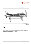
1
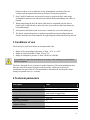
User Manual and Technical Description Care Bed Version 01.220 11 January 2008 1 Dear Customer Thank you for buying CareWell health care equipment and furniture. We feel sure that our equipment will meet and exceed your expectations. We are working hard to change the way that people see and feel about health care to make it a nurturing, comforting and reassuring. The following manual is important for getting the full potential out of our equipment and furniture, please read it before use. If you need further information, or would like to order more of our equipment and furniture, please contact us on the following coordinates: www.carewell.com.au [email protected] Toll Free 1300 30 32 88 Telephone +61 2 9564 0684 Facsimile +61 2 564 0940 2 AS/NZS 3200.2.38:1997 EU Directive equivalent 93/42/EEC The signatory CareWell Health Pty Limited 78 – 90 Old Canterbury Road Lewisham NSW 2049 The products described below are specifically developed and intended for the aged care nursing industry and have been derived in consultation with operators in that industry to suit their specific needs. This letter serves to confirm that the referenced products in the form distributed by ourselves meet the safety and stability requirements of AS/NZS 3200. The following Standards apply: o AS/NZS 3200.2.38:1997 − Protection against mechanical hazards − Protection against excessive temperatures − Constructional Requirements o TGA Medical Device Class 1 This declaration of conformity becomes invalid if the products are altered without the written agreement of the manufacturer. Product description Hospital Care beds Croft, Oden and Contempora Signed Jason Falinski: Managing Director 3 Contents 1 Introduction .............................................................................................. 6 WARNING.............................................................................................. 6 1.1 Means of delivery................................................................................. 6 3 Conditions of use ....................................................................................... 8 4 Technical parameters ................................................................................. 8 Warning: ............................................................................................... 9 5 Variants specification.................................................................................. 9 Add-ons to standard bed: .............................................................................. 9 Head-boards and foot-boards in a range of colours and finishes................. 9 Your choice of bed colour ....................................................................... 9 6 Bed description ........................................................................................ 10 Figure No. 3 — Bed description ............................................................. 10 7 Bed installation and putting into the operation............................................ 11 7.1 Connecting the bed to the mains......................................................... 11 7.2 Siderail installation ............................................................................. 11 Figure No. 6 — The bed looking from head to foot end with the siderail attached in the collapse position. ........................................................... 12 Figure No. 7......................................................................................... 12 8 Bed positioning ........................................................................................ 13 8.1 Supervisory control panel ................................................................... 13 8.2 Handset Operation ............................................................................. 13 Figure No. 12 — Handset ...................................................................... 13 9 Bed ends................................................................................................. 14 10 Siderails ................................................................................................ 15 Figure No. 20 “Zero position” of siderails ................................................ 15 Figure No. 23 —“Full- position” of siderails ............................................. 16 10 Manipulation with siderails ...................................................................... 17 Figure No. 25 — Manipulation with siderails............................................ 17 4 11 Castor control ........................................................................................ 18 Figure No. 28 — Castor control in unlock and lock position ...................... 19 12 Fold down foot board ............................................................................. 19 13 Accessories............................................................................................ 20 13.1 Self Help and IV pole........................................................................ 20 14 Safety night light.................................................................................... 20 15 Mattress platform cover removal ............................................................. 20 16 Cleaning and disinfection ........................................................................ 22 16.1 Basic instructions before cleaning ...................................................... 22 16.2 Cleaning procedure .......................................................................... 22 16.3 Extent of cleaning ............................................................................ 22 16.4 Cleaning the siderails........................................................................ 23 17 Troubleshooting ..................................................................................... 23 18 Storage ................................................................................................. 24 19 Maintenance .......................................................................................... 24 20 Environmental protection ........................................................................ 24 21 Guarantee and service ............................................................................ 25 22 Record of performed service procedures and regular service maintenance .. 26 23 Bed completion certificate ....................................................................... 27 24 Serial label............................................................................................. 27 25 Contacts ................................................................................................ 28 5 1 Introduction The adjustable care bed is designed for the hospitalisation of patients particularly on standard aged care facilities both low and high care environments. The manufacturer does exclude installation in hospitals or intensive care units, but this can be considered only on the basis of the responsible selection of the health care provider. The bed is produced in accordance with international norms, in particular Australian Standards AS 3200.3.28: 1997 safety and stability provisions. The manufacturer works according to the certified quality management system under the norms EN ISO 9001:2000 and EN ISO 13458:2000. Before handling the bed, you must become acquainted in detail with this manual. All actions and handling of the bed must be performed in accordance with the manual! Any other actions that are inconsistent with the manual or for the purpose of use of the bed are performed at your own risk and the manufacturer shall not be liable for any damage. Therefore it is important that the manual be available to the user throughout the bed’s service life! WARNING The manufacturer shall not be held liable for any damage, injuries or accidents arising from inattentiveness, bad, negligent or erroneous handling. The manufacturer, seller or trained person shall perform the basic instructions for handling the bed. The safety features for operating the bed and the instructions concerning the bed handling must be strictly observed. 1.1 Means of delivery The bed is supplied either completely assembled or with foot and head ends package separately requiring insertion on site. In the case of the second means of delivery, all that is required is for the bed to be removed from the box and the head and foot boards inserted. According to the delivery note an inspection must take place on site to make sure the entire delivery is complete. Any faults or damage must be immediately reported to the carrier and the supplier in writing. 6 When traveling with the bed, loading and unloading it, care must be taken that the bed brakes are unlocked. The bed castors are designed for use in an indoor environment and for travel on even, smooth and clean floors (ceramic floor tiles, linoleum, cast floors and the like). The castors may become damaged when traveling with the bed along a rough, uneven or dirty surface. Safety instructions Before using the bed, you must read the manual and handle the bed in accordance with it The bed may not be used if faults have been detected on it that may injure the patient, staff or a third person, the bed or the surrounding interior The bed may only be handled by persons who, by their knowledge or practical experience, provide a guarantee that the bed shall be handled without any problems The operating staff should acquaint the patient with the control functions that are designed for the patient (control panel, supporting handrail for leaving the bed) The user (operator) should, before using the bed, be comfortable with the functionality and faultlessness of the bed The bed may be used only on even and solid floors and under the conditions set forth in the paragraph “Conditions of use” The bed may not be overloaded even for a brief period The height of the mattress platform must be adjusted to the height and condition of the patient If there is a patient on the bed, the castors must be locked (with the exception of when traveling with the bed) – an unlocked bed poses a risk of injury to the patient when leaving the bed or when supporting himself No other people may sit on the bed When handling the mobile parts of the bed, care must be taken that the patient, other people or objects do not get trapped during its movement If a lifting pole or infusion stand is fixed to the bed during movement, lifting or tipping, increased attention must be taken to the space around the lifting pole and infusion stand so the equipment does not get damaged Before cleaning or maintaining the bed, the supply cable must be disconnected from the mains The bed may not be used where there is a danger of explosion or in the presence of inflammable liquids When repairing the bed, only original materials and components may be used; when replacing damaged parts with inappropriate materials and components, the manufacturer does not guarantee against any damage that can occur When maintaining and cleaning the bed in the space between the undercarriage and mattress platform, the adjustment functions on the central control panel must be 7 blocked so there is no accident due to any unintentional activation of the foot switches and subsequent downward movement of the mattress platform Only CareWell mattresses and accessories may be used on the bed; when using incompatible mattresses the siderails may function badly and endanger the safety of patients When transporting the bed, the mains cable must be suspended with the aid of a plastic hook on the bed end or other safe place to prevent the cable from being run over and damaged An inspection should be made at least once a month for wear of all mobile parts The doctor treating the patient or another responsible person providing treatment decides about the use of the handrails for supporting the patient when leaving the bed 3 Conditions of use The bed may be used in an indoor environment where the: Range of the surrounding temperature is from + 10°C to + 40°C Range of relative humidity is from 30% to 75% Range of atmospheric pressure is from 700 hPa to 1060 hPa It is essential to consult the manufacturer in advance when wanting to use the bed for different purposes. The bed is designed for use in rooms for medical purposes. Electrical installations must therefore meet local norms laying down the necessary conditions for electrical installations. In spite of this it is recommended to disconnect the bed from the mains during exceptional cases (i.e. a storm). 4 Technical parameters Description Value External Dimensions Mattress Platform Dimensions Castor Wheels 970mm wide x 2060mm long 910mm wide x 2000mm long Multi directional, tandem set, dual caster, with central locking feature From 185mm to 790mm 85kg nett 75o 390mm Height Adjustable Weight Backrest positioning Siderail height above mattress platform (without mattress) Safe working load 185kg 8 Max Self Help Pole Lifting Load Siderail height above the mattress platform (without the mattress) Safe Working Load (SWL) Type of protection against electrical current Level of protection against injury from electrical current Electric motor operation mode (load factor) 75kg 185kg Class 1 Applied part type B 10 per cent max. 2min/18min Warning: The bed is powered from the mains, meaning sensitive instruments may be disrupted. In order to reduce the risk of undesirable electrical magnetic effects as much as possible, the bed is manufactured in accordance with the safety and stability requirements of AS/NZS 3200.2.38:1997. In order to avoid these problems, the bed must be used in accordance with this manual. 5 Variants specification Optional features - according to the customer’s wish: Siderails 3-segmented 1500mm length siderails adjustable up to 45 cm Castors ProCare tandem dual castors: 75mm ProCare dual castor: 75mm Control elements Handset Handset with an adapter for easy connection (plug and play) Other features Add-ons to standard bed: Head-boards and foot-boards in a range of colours and finishes Timber trim bed frame (with matching head and foot-boards). Extended length Your choice of bed colour Your choice of bed length 9 6 Bed description 1 3 2 4 5 7 6 8 Figure No. 3 — Bed description 1. Foot board (optional) 2. Foot panel (removal) 3. Manual knee break electric knee break (optional) 4. Electric back rest panel (removable) 5. Remote control pendant 6. Wall protector 7. Central Locking Castor wheel 8. X lifer function 18 17 16 15 14 13 12 1 2 3 4 5 6 7 8 9 10 11 10 7 Bed installation and putting into the operation 1. Remove the packaging from the bed and dispose of it in an environmentally. 2. According to the delivery note, check that the delivery is complete; check whether any visible damage has occurred to the bed during transport. 3. Carefully read the user manual. 4. Remove safety ties from siderails and electrical wiring. 5. If the bed is delivered with dismantled ends and siderails (two beds stacked above each other), these parts of the bed must be installed according to the instructions in the chapters “Siderail installation” and “Bed ends”. 6. Should the bed be equipped with a satellite control panel, it should be installed according to the information in the chapter “Satellite control panel installation“. 7. If the temperature during bed transport or storage is different from the operating temperature, it is necessary to leave the bed without connection to the net for 24 hours to adapt it to internal conditions. 8. Connect the bed to the mains including its connection for balancing the potential (see Subchapter 7.1, 7.3.) and charge the battery back up (see Sub-chapter 7.2.). 9. Check the functionality: Adjust the individual parts of the mattress platform to the maximum position, the mattress platform height and tilting to the maximum and minimum position Check the faultless function of the castors and central control, extension of the mattress platform, removal of the head and foot ends Check all the functions of the control panel Make sure the siderail function works without any problems (locking in the upper position) Check for obstructions both above and below the bed frame and position the bed so that it can operate through the full height range without any chance of collision. Head end of the bed must be a minimum of 300mm from the wall initially. Always engage the brakes when the bed is positioned or unattended. 7.1 Connecting the bed to the mains The mains cable for feeding the bed forms an integral part of the bed so the bed is connected by inserting the plug on the mains cable into a 240V socket. 7.2 Siderail installation We recommend that the bed be installed by two people. 11 1. After removing the packaging of both beds, place the right and left siderails including the corner segments along the length of the bed as in figure. At the same time the siderails must be positioned so that the foot end of the siderail faces the foot end of the bed. The foot ends of the siderail can be easily recognised because they can be extended telescopically. Both bed ends remain on the mattress platform if this is an ordered bed component. A Figure No. 6 — The bed looking from head to foot end with the siderail attached in the collapse position. 6 B Figure No. 7 — The bed head to foot end with the siderail attached and at full height. 2. Secure all 4 corner segments of the siderails with the supplied screws (A and B). The joining section that needs to be tightened to fasten siderails to the bed pictured with the securing device that holds the siderails in place. . 12 8 Bed positioning The various controls stated in the following chapters can be used for the electrical adjustment of the bed. The selection of the controls corresponds to the bed equipment ordered by the customer. 8.1 Supervisory control panel A nurse lock is optional and can be located at the end of the bed. This gives carers control over the bed position and locks out patients from adjusting the bed on their own. 8.2 Handset Operation The handset can be used for positioning the sections and for height adjustment of the mattress platform of the bed by either the patient or the carer. The use of the handset is the same as the supervisor panel: A B Always check for obstruction before raising and lowering Figure No. 12 — Handset 1. To position the backrest use controls labeled A. 1.1 to raise the backrest press down on the up arrow. 1.2 to lower the backrest press down on the down arrow 2 To position the platform mattress 2.2 to raise the platform mattress press down on the up arrow 2.3 to lower the platform mattress press down on the down arrow 13 Before using the control, the operating staff should explain to the patient the manner and form in which the bed can be positioned. If the medical staff admits that the patient’s condition is inappropriate for the patient to be able to adjust the bed on his own, the bed’s position adjustment should be locked in the above described manner with the aid of the nurse lock out. 9 Bed ends The beds are equipped with two removable high-pressure laminate and aluminium profiled ends. Before starting to use the bed, the ends must be fixed to it. Both the head and foot ends of the beds are removable by simply pulling them up as shown. When removing the ends, the end must be gripped with both hands and carefully pulled up in the direction of the arrows to remove them. When placing the ends back on the bed, the reverse procedure is used. 14 10 Siderails The beds are always equipped with low-profile siderails. The siderails consist of three parallel, horizontal bars mutually connected above each other and are accessible on both sides of the bed. The siderails can be adjusted to three height levels and each has its specific use. Figure No. 20 “Zero position” of siderails Zero position This level is adjusted when the siderails are completely slid under the mattress platform. The siderails do not extend from the bed and enable the nurse to gain access right to the edge of the mattress. The bed can be placed right next to a stretcher or another bed, so the patient can be moved safely. Semi-position The siderails are 28 cm in height above the mattress platform. This position can be used to prevent patients from falling off the bed who, due to their mental condition, are not expected to try to leave the bed spontaneously. In no case is this position designed for a patient in shock, restless patients, or patients with mental disorders. 15 Figure No. 23 —“Full- position” of siderails Full-position The siderails are 45 cm in height above the mattress platform. Siderails at this height ensure safety even when active antidecubitus mattresses up to 23 cm thick are used. Extra high position (option) The siderails are 59 cm in height above the mattress platform. Siderails at this height ensure safety even when active antidecubitus mattresses up to 37 cm thick are used. A siderail adjusted only to the “High” and “Extra High” position can be considered a full siderail in accordance with the technical norms that apply to an adjustable bed. These two positions guarantee the norm prescribed height of 22 cm between the upper edge of the siderail and standard used mattresses. 16 10 Manipulation with siderails A Figure No. 25 — Manipulation with siderails Lowering the siderail (downwards): 1. ensure that there is nothing leaning or resting on the siderail prior to operation. 2. pull the locking handgrip outward (away from the bed) [A] 3. adjust the siderails to any of the selected lower positions by smoothly sliding them downwards Raising the siderail (upwards): Grip the upper siderail with both hands not the locking handgrip and smoothly slide upwards adjusting the required siderail height to one of the locking positions (the siderails lock themselves in one of these positions). 17 11 Castor control Central Locking Castor All four castors can be locked by pressing down on the locking bar located at the end of the bed (a). The castors can then be unlocked by raising the bar with the operator’s foot. A Fig 28.0 Single Locking Castor The beds are equipped with castor control. [The Oden bed comes standard with central locking feature]. The controlling brake levers are located on each of the wheels. Fig 28.1 Unlock 18 A Fig 28.2 Lock Figure No. 28 — Castor control in unlock and lock position 1. Each castor can be locked with the foot. 2 A castor is locked by pushing down on the larger lever that extends further, and is at the bottom of the two lever system (marked A) 3 Locking the wheel pushes the smaller lever higher as shown in fig 28.2. 4 Unlocking the wheel requires the user to push down on the smaller top lever, which resets the levers back to the formation in fig 28.1 readying it to be locked once more. Care must be taken to make sure the castor brakes are always activated when the bed is standing, is being assembled or dismantled so that the bed does not move accidentally. When moving the bed, care must be taken that the bed be disconnected from the mains and the bed does not run over the mains cable. The mains cable must be suspended when the bed is moved using the plastic hook placed in an appropriately safe place on the bed 12 Fold down foot board If necessary, the bed mattress platform can be extended by up to 17 cm at the foot end using the following procedure. 1. release the extension by lifting the foot board until it clicks in to position. 2 Once it is clicked in to position it is possible to lower the footboard to a 90o angle. 3. to restore the foot board to its original position requires the same process: 3.1 pull the foot board until it clicks into position unlocking the board 3.2 at this point return the board to its vertical position and lower it until it is locked in position. 19 13 Accessories It is possible to use accessories for the bed designed by the manufacturer. The use of different accessories not compatible with the bed may cause a safety risk or damage the bed respectively. In such cases the manufacturer will not be liable for the consequences. 13.1 Self Help and IV pole There are 2 sockets to store the lifting or IV pole that are found in the corners at the head end. The max. Load of the IV stand is 8 kg, the load of one plastic hook is 2 kg. The infusion stand is not designed for the attachment of infusion pumps. The self help pole is placed in the socket so the pin falls into the slot. The lifting pole must be equipped with a triangular plastic handrail with an adjustable band. By shortening this band, it is possible to adjust the appropriate height for the patient. When turning the lifting pole in the socket away from the bed and using the lifting pole in this position, there is a serious risk of turning the bed over. That is why the lifting pole cannot be fixed this way. The only two correct positions for the lifting pole in the socket are by the defined locking of the lifting pole pin in one of the slots in the socket. 14 Safety night light The bed can be equipped as requested with undercarriage lighting that helps the patient or operator to find their way around the room with switched off or dimmed lights. The lighting is constantly switched on when connected to the mains, and is automatically switched off when operating on a backup battery. 15 Mattress platform cover removal The Image bed has a four-section mattress platform (a backrest, pelvic rest, thigh rest and calf rest), and its surface consists of removable metal covers. By simply removing the infection pads, the inner bed construction can be fully cleaned and disinfected. After removing the covers, it is thereby possible to clean all the metal 20 parts and mechanisms of the mattress platform and all the parts of the electrical installations (backrest and thigh rest motors, mains box, battery box, control unit box, cables). 21 16 Cleaning and disinfection 16.1 Basic instructions before cleaning In order to disinfect the bed, use detergents designed only (for cleaning the equipment) for standard use in healthcare. Do not use abrasives (scouring powder), scourers and other materials that could amage the coating. Do not use corrosives, caustics or strong acids. Clean by wiping with damp and properly wrung cloth. Do not use detergents that could alter the structure or behaviour of the plastics (petrol, toluene, acetone, etc.). The beds are not designed for maintenance in automatic bed washers. The beds are not designed for cleaning with a current of pressure water, spraying, showering or steam cleaning. We cannot be liable for any damage or risk of damage if inappropriate cleaning or disinfectant detergents are used. 16.2 Cleaning procedure 1. Adjust the mattress platform to (a higher) the highest position and also adjust the position of the back and thigh rest so it provides access for cleaning the back part rests. 2. Block the adjustment function on the nurse control panel, including the foot controls to prevent accidental bed movement and injury during cleaning. 3. Disconnect the bed from the mains. 4. Move the bed to a place where cleaning will take place and then lock the bed brakes. 5. Clean and disinfect the bed to the appropriate extent. The extent of the cleaning and disinfection should depend on the intended purpose and level of bed contamination (see the following chapter). 16.3 Extent of cleaning Level of cleaning Extent of decontamination – bed parts 1. Daily cleaning Surfaces exposed to daily contact with the patient and operator: All control elements for bed adjustment All handling features (back and thigh rest handrails, CPR handrail) The entire area of the ends, including the side columns and parts beneath both ends The entire siderail area (at the highest adjusted position) 22 Freely accessible mattress surface Supporting handrail Side accessory bars 2. Cleaning with a new patient. Bed parts stated in point 1 and also: All plastic mattress platform covers Plastic undercarriage cover Column unit surface The mattress from all sides Freely accessible metal parts on the mattress platform Tubes for feeding cables between the undercarriage and the mattress platform Surroundings of the lifting pole/infusion stand sockets Protective corner bumpers Central castor, control castors and levers 3. Complete cleaning and disinfection. Bed parts stated in point 1 and 2 and also: All the inner construction parts accessible after the removal of the mattress platform plastic covers as mentioned in the chapter “Removal of the Mattress Platform Covers” Inner parts of the corner segments of the siderails (see the next subchapter) 16.4 Cleaning the siderails The siderails, which consist of 3 profiles, are good to decontaminate during daily cleaning. Clean the siderails daily by adjusting them to the highest position. 17 Troubleshooting Sign of fault Cause Removal of the fault One of the components of the electrical installations is faulty (control, controlling unit, motor). Try controlling the function in question with the aid of another control. If only the control in question is not working, order a new control from the manufacturer’s service organisation. If the other controls do not work as well, order the servicing of the bed. Do not repair the electric motor, power box and other electrical parts if a fault occurs. Do not open the protective electric motor or power box cover. 23 18 Storage For problem-free storage we recommend: Disconnecting the bed from the electric mains feed Dismantle the accessories (lifting pole and so on) Wrap up the bed and accessories or cover so that the coating and plastic parts are not damaged. The same conditions apply to the storage space areas as for the work environment. 19 Maintenance Because some parts of the bed may suffer wear and tear due to use, cleaning and disinfection, inspect the following places on the bed at least once every 3 months: 1. side rail – wipe and lubricate with silicon oil 2. joints and pins of the adjustable mechanisms (backrest, thigh rest and calf rest) – wipe and lubricate with silicon oil 3. motor pistons – wipe and lubricate with silicon oil 4. upper columns fixation – check if the screws and nuts providing connection between column stirrup and mattress platform are well tightened Other special maintenance procedures are qualified work, which we recommend to be carried out by a professional service. The user is obliged to ensure a preventive bed inspection after a 12-month period, which will be performed by the manufacturer’s service, or the service firm authorised to perform this activity. The manufacturer issues the relevant certificate to these service organisations and the inspection is confirmed by the relevant service worker in the list of performed service activities. If you discover irremovable faults or inconsistencies during maintenance, the bed may not be used further. In such a case immediately contact the manufacturer (or seller). 20 Environmental protection CareWell is aware of the necessity to protect the environment for future generations and therefore devotes great attention to the development, innovation, planning, production and use of such technology and materials that are environmentally friendly. 24 This product is constructed from materials that are environmentally friendly. The product does not contain dangerous substances based on cadmium, mercury, asbestos, PCB or CFC. The operational noise-level of the product meets the requirements for the protection of public health against undesirable noise and vibration in protected indoor building premises. Wooden parts used in the product are not made from exotic wood such as mahogany, jacaranda, ebony, teak, grenadil or santo, and do not come from the Amazonian rainforests or other virgin forests. All packaging is marked in accordance with the packaging regulations. The product contains recyclable steel, plastic and electronic components – to optimise recycling once the operation of the product ends, separate the individual parts so that the raw materials from which the product is made can be put to further use. 21 Guarantee and service There is a 36-month guarantee on the bed commencing the date of delivery unless the purchase contract states otherwise. The manufacturer or authorised service organisation performs guarantee and post-guarantee repairs based on a written qualification certificate to perform these activities. The manufacturer issues the relevant certificate. 25 22 Record of performed service procedures and regular service maintenance Purpose and Description Date Performed By I confirm that technical staff have undertaken the repairs has described above and the equipment is now functioning normally. ........................... .............................................. ............................................ date CUSTOMER SIGNATURE 26 23 Bed completion certificate Order Number Customer Model Number Supplier Acceptance Date Serial Number Guarantee Period I confirm that the operating staff has been trained for the purpose of becoming acquainted with the use of the bed. ........................... .............................................. ............................................ date CUSTOMER SIGNATURE This completion certificate also serves as a guarantee certificate. When in contact with the seller the customer shall state the number of the order or number of the products. 24 Serial label When communicating with the manufacturer, supplier or service organisations the bed must be identified with the aid of the model and serial number stated on the serial label (on the outer side of the mattress platform frame). 27 25 Contacts Date of issue: 10 February 2007 Conformity declaration issued by: CareWell Health Pty Limited 6 Durdans Avenue Rosebery NSW 2018 www.carewell.com.au [email protected] Toll Free 1300 30 32 88 Telephone + 61 2 9667 8770 Facsimile + 61 2 9669 4830 As the producer of the product - name (brand): Oden Variants of the product: The variants are specified in the technical documentation. Description and function designation: Positionable bed for standard care Clssification of the product as the medical device: Class I nonsterile, without measuring function A) Declaration I declare that the said product is designed for an aged care environment and meets the safety and stability requirements under the AS/NZS 3200.2.38:1997 and that measures have been taken to ensure the conformity of all the products brought to market with basic requirements. B) Fulfilled technical requirements This product's characteristics comply with the safety and stability technical parameters related to it and stated in AS/NZS 320.2.38:1997 which stipulates the technical parameters for healthcare products. C) Means of assessing conformity Conformity was assessed by the procedure stated in AS/NZS 3200.2.38: 1997 28