1
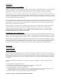
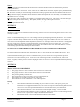
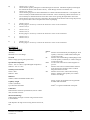
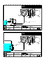
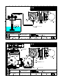
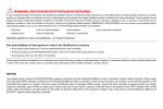
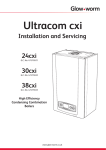
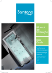
100 SERIES
Self-Powered Contents Gauge
USER MANUAL
UM/100/D/04
SECTION 1
INTRODUCTION TO 100 SERIES
Measurement Resources 100 Series Hydrostatic Tank Contents provides accurate reliable self-powered remote indication
of tank liquid contents. Used on freely vented storage and process tanks for land based, marine, and vehicular
applications. Each instrument comprises a sensor with interconnecting sealed capillary to a remote dial indicator.
Tank mounted sensors are available for either external or internal fitting and are interconnected to the remote indicator by
a customer specified length of sealed fire retardant plastic component or stainless steel capillary. Stainless steel external
sensors E, can be supplied with an optional extra ¾” BSP non-return dry break valve whereby the sensor may be removed
from the tank without first draining the contents.
External EF, EFM sensors are flanged connected into the side of the tank and is more commonly used on more viscous or
corrosive liquids. Internal installation IF Series is supported on a steel tube from a flange and is generally used for
inground tanks. IM style sensors were developed for tanks or compartments where only internal fixing can be used; a
typical example is a ships double bottom tank.
A range of indicators is available, which are designed to present clear, easy to read information. 100mm, 150mm and
250mm nominal diameter indicators are offered as standard. All indicators are stainless steel and weatherproof.
UNDER NO CIRCUMSTANCES SHOULD ANY ATTEMPT BE MADE TO DISCONNECT ANY PART OF THE
SEALED SENSOR CAPILLARY INDICATOR SYSTEM.
DESCRIPTION OF “OPERATION”
The sensor is installed so the head pressure of process liquid acts against a stainless steel diaphragm contained in the
stainless steel sensor this is connected, by capillary tubing, to a rated diaphragm within the remote indicator. The total
internal volume of the diaphragm, capillary tubing and senor is charged with an inert temperature stable gas and sealed.
When the sensor is fitted to the tank or vessel the liquid head hydrostatic pressure acts on the diaphragm and causes
pressure to be transmitted via the capillary tubing to the indicator. With an increase in pressure the indicator diaphragm
distends and causes a precision mechanism to move the pointer over the scale. This is graduated in mass, head or
volume units to suit the application. Providing constant self powered remote indication of the tanks liquid level.
SECTION 2
INSTALLATION
Capillary and Indicator
To gain long life and trouble free operation, care should be taken during installation to avoid damage to the capillary.
Whenever possible, installation should commence by fixing the indicator in position, reducing the risk of the instrument
being damaged when the capillary is unrolled. With the internal sensors IF and IM it may not be practical to commence
by mounting the indicator first. In such a case the indicator should be protected from mechanical damage during fixing
the capillary.
The capillary should be carefully unrolled. Do no pull the coil apart and attempt to correct the spring-like effect by
pulling.
The following guidelines should be followed:
♦ Protect the sensor diaphragm against the ingress of foreign matter or sharp objects.
♦ Secure the capillary at the start and completion of every bend.
♦ Bends should not have a radius of less than 25mm.
♦ For underground runs, enclose the capillary in a duct. Although the capillary covering can be buried. This is not
recommended unless precautions are taken to prevent damage from later excavation work.
♦ Ensure the capillary is not exposed to higher than ambient temperature.
ON NO ACCOUNT ENCASE THE CAPILLARY IN CONCRETE
Sensor
To ensure accurate measurement the tank-mounted sensor must be installed at the level detailed in the purchase
order/questionnaire.
E - Side of tank screwed connection. Sensor connected via ¾” BSP female connection, surplus capillary should be neatly
coiled close to the tank.
IF - The sensor assembly is inserted through and bolted to tank top, a gasket should be used between tank and sensor
flange sufficient capillary should be coiled at the tank to enable the complete IF sensor assembly to be withdrawn from
the tank for service or cleaning.
IM - The sensor with the stainless steel capillary is passed through the tank cut-out. The sensor secured at the height
specified on the purchase order/drawing. The capillary fixed to 4” flange with its gasket secured.
EF, EFM - The sensor is flanged to the tank outer wall, with an opening of not less than 100mm. A gasket compatible
with the liquid should be used.
SECTION 3
MAINTENANCE
Maintenance operations are limited to periodical cleaning of the indicator face and ensuring that the sensor is kept clear
of sludge or solids.
To cleanse the congealed fluid or sludge from E type sensors the following procedure should be adopted. Isolate the
sensor from the tank by closing the valve or unscrewing from the optional spring loaded dry break valve. It is advisable
to place a container directly under the sensor to catch any leakage during removal. Place the sensor in a container of
non-corrosive solvent compatible with the liquid being measured. For example, for fuel oils use kerosene. Gently agitate
the sensor in the solvent until the congealed liquid is seen to be leaving the connection of the sensor. To assist in
dislodging stubborn deposits a small quantity of solvent may be poured into the sensor and gently shaken. Continue
with cleansing operations until all sludge has been expelled.
ON NO ACCOUNT INSERT PROBE INTO THE SENSOR OR ATTEMPT TO DISMANTLE THE SENSOR.
If contacting Measurement Resources for information or advice. Please quote the serial number of the gauge. This is
located at the 6 o’clock position on the indicator dial face.
Cleaning EF/EFM and IM types of sensors is seldom necessary as these sensors have a larger diameter pressure
sensitive area in contact with the process. In the rare event of this being needed. First drain the tank, remove the
sensor, and gently wash the pressure sensitive diaphragm with a non-corrosive solvent compatible with the liquid being
measured.
SECTION 4
MALFUNCTION AND REMEDY
Symptoms
a)
The gauge indicates a value more than which is known to be in the tank.
b)
The gauge indicates a value less than which is known to be in the tank.
c)
The pointer gradually returns to zero.
d)
The pointer shows no movement with a variation in the liquid level.
e)
The pointer starts to make a second sweep of the scale.
f)
The Indication is erratic and unstable - varies with temperature.
Remedy
A)
1.
2.
3.
4.
Check that the tank dimensions including any slope relative to sensor, and specific gravity with
information given to Measurement Resources at the time of order. Providing the actual dimensions are
within 10% of data supplied with the order, a new dial can be supplied to correct discrepancies. A
variation over 10% will require the instrument to be returned to the factory for recalibration.
Check that the tank sensor is not choked with congealed liquid or sludge. Clean as needed.
Check that the tanks ventilation system is not blocked. If the gauge shows a normal reading when the
manhole cover is opened, the vent pipe should be checked/cleared.
Check that the pointer is not touching the dial or indicator glass window.
100 Series User Manual
UM/100/C/04
Page 1
B)
1.
2.
3.
4.
5.
Check as in a) 1. Above.
Check that the capillary tubing has not been damaged or fractured. Should the capillary be damaged,
the instrument must be returned to the factory. Such damage cannot be rectified on site.
Check as a) 2. Above.
Check that the gauge has not been calibrated from a datum other than tank bottom. Your dipstick will
almost certainly be calibrated from the bottom of the tank. Dials commencing with the first mark as ‘0’
will invariably be calibrated from the centre line of the sensor ignoring the liquid below the sensor.
Check that the sensor has not been connected to the feed pipe from the tank and is being subjected to
loss in pressure due to flow of liquid or the effects of pumping.
C)
1.
2.
3.
Check as in b) 2.
Return gauge to our factory or ask for the assistance of one of our technicians.
Check as in b) 5.
D)
1.
2.
3.
Check as in a) 2.
Check as in a) 4.
Return gauge to our factory or ask for the assistance of one of our technicians.
E)
1.
2.
Check as in a) 1.
Check as in a) 3.
F)
1.
2.
Check as in 1) 2.
Return gauge to our factory or ask for the assistance of one of our technicians.
SECTION 5
SPECIFICATION
Accuracy
Maximum error ±1.0% Range
Overload
200% of range (option greater protection).
Operational Temperature
Sensor - 10°C to +100°C (optional higher temperature)
Indicator - 10°C to +50°C
Weatherproof Protection
Sensor - IP67
Indicator - IP65
Sensor
E
Stainless steel welded body and diaphragm. Rear
capillary connection; ¾” BSP female running nut
connection to tank.
EF
Stainless steel welded flange and diaphragm. Rear
screwed capillary connection; 4” Table E flanged
connection to tank.
EFM
As above but with Teflon® mask and gasket to
process.
IF
Stainless steel sensor welded to 20mm stainless
steel support pole. Stainless steel 4” Table E
flanged connection to tank.
IM
Stainless steel sensor, and in tank mounting
bracket. Stainless steel capillary to 4” table E
stainless steel flange.
Indicators
100mm, 150mm and 250mm stainless steel
Capillary Length
3 metres (standard)
Up to 20 metres maximum
Sensor can also be supplied to the original MS
and MIT/MIS standards.
Teflon® is a registered trademark of Dupont.
Calibration
Dial marked in customer specified mass, head or volume
units, and tank reference.
Measurement Range
Tanks Depths 1 through 15 metres using external sensors
E, EF and EFM.
Tank Depths 1 through 3 metres using internal sensors IF,
IM.
100 Series User Manual
UM/100/C/04
Page 2
1
2
3
4
5
6
7
8
9
10
A
11
12
13
14
15
16
DIMENSIONS IN mm
100 SERIES
INDICATORS
OA
133
196
285
100 NOM. DIA.
160 NOM. DIA.
250 NOM. DIA.
B
52
61
58
OC
112
173
250
D
55
86
142.5
E
18
20
20
F
80
80
NA
OG
100
158
NA
OH
5
5
6
PCD
117
178
270
A
B
A
F
B
ø G
C
600
800
D
1000
200
C
400
1200
LITRES
0
1400
D
at sp.gr. 0.85
H
PCD
E
FLUSH PANEL
MOUNTING
WALL MOUNTING
F
PANEL CUT-OUT
E
90
22
G
116 DIA.
H
H
CAPILLARY TYPE "A" OR "B"
I
I
3/4" DRY BREAK VALVE
TRANSMITTER TYPE "E"
CERTIFIED
J
ALL DIMENSIONS ARE IN MILLIMETERS
UNLESS OTHERWISE STATED
MATERIAL AND SPECIFICATION
K
DATE
7/06/2004
DRAWN
BS1
TITLE
2
3
4
3
DRAWING No
100 SERIES SELF POWERED
CONTENTS GAUGE TYPE "E"
NTS
2
1
FINISH
SCALE
4
J
33-37 COLLEGE ST
GLADESVILLE NSW
REFER TO MANUAL
AND DRAWINGS
CHECKED
5
6
7
8
5
6
7
8
9
10
9
10
11
12
13
12
14
13
14
SHT 1
OF 1
15
15
16
16
DIMENSIONS IN mm
100 SERIES
INDICATORS
100 NOM. DIA.
160 NOM. DIA.
250 NOM. DIA.
A
11
A4
100 TYPE "E"
OA
133
196
285
B
52
61
58
OC
112
173
250
D
55
86
142.5
E
18
20
20
F
80
80
NA
OG
100
158
NA
OH
5
5
6
PCD
117
178
270
A
B
A
F
B
ø G
C
600
800
400
1000
200
C
D
1200
LITRES
1400
D
at sp.gr. 0.85
0
H
PCD
E
FLUSH PANEL
MOUNTING
WALL MOUNTING
F
PANEL CUT-OUT
E
4" TABLE "E" SENSOR
STANDARD
130
G
H
H
CAPILLARY TYPE "A" OR "B"
I
J
CERTIFIED
ALL DIMENSIONS ARE IN MILLIMETERS
UNLESS OTHERWISE STATED
MATERIAL AND SPECIFICATION
K
DATE
07/06/2004
DRAWN
BS1
FINISH
SCALE
TITLE
3
DRAWING No
100 SERIES SELF POWERED
CONTENTS GAUGE TYPE "EF"
NTS
2
4
5
6
7
J
33-37 COLLEGE ST
GLADESVILLE NSW
REFER TO MANUAL
AND DRAWINGS
CHECKED
I
8
9
10
11
100 TYPE "EF"
12
13
14
A4
15
SHT 1
OF 1
16
K
K
1
2
9
10
100SERIES
INDICATORS
100 NOM. DIA.
160 NOM. DIA.
250 NOM. DIA.
A
OA
133
196
285
11
B
52
61
58
12
13
DIMENSIONS IN mm
OC
D
112
55
173
86
250
142.5
E
18
20
20
14
F
80
80
NA
15
OG
100
158
NA
OH
5
5
6
16
PCD
117
178
270
A
B
B
A
4" TABLE "E" FLANGE
ASSTANDARD
CABLE GLAND, PG9
800
600
400
D
ø G
1000
200
C
C
F
1200
LITRES
1400
D
at sp.gr. 0.85
0
H
PCD
E
125
3
FLUSH PANEL
MOUNTING
WALL MOUNTING
F
PANEL CUT-OUT
E
G
3/4" NOMINAL BORE PIPE
(316 SS)
CAPILLARY TYPE "A" OR "B"
HEX RUNNING NUT
3/4" BSP THD.
H
H
I
I
CERTIFIED
J
ALL DIMENSIONS ARE IN MILLIMETERS
UNLESS OTHERWISE STATED
MATERIAL AND SPECIFICATION
K
DATE
07/06/2004
DRAWN
BS1
1
FINISH
SCALE
TITLE
100 SERIES SELF POWERED
CONTENTS GAUGE TYPE "IF"
NTS
2
3
2
4
3
5
4
6
5
7
6
8
7
10
9
3.25"
11
10
100SERIES
INDICATORS
100 NOM. DIA.
160 NOM. DIA.
250 NOM. DIA.
3.25"
2"
9
8
A
10"
CUT-OUT
J
33-37 COLLEGE ST
GLADESVILLE NSW
REFER TO MANUAL
AND DRAWINGS
CHECKED
OA
133
196
285
11
B
52
61
58
DRAWING No
A4
100 TYPE "IF"
12
13
12
14
13
DIMENSIONS IN mm
OC
D
112
55
173
86
250
142.5
E
18
20
20
15
14
F
80
80
NA
15
OG
100
158
NA
OH
5
5
6
SHT 1
OF 1
K
16
16
PCD
117
178
270
A
B
11.25"
TOINDICATOR
A
B
F
ø G
RECTANGULAR FLANGE
12.5" x 4.5" (EXTERNAL)
600
1200
LITRES
0
ST. ST. CAPILLARY
ST.ST. ARMOURING
6 HOLES EQUI-SPACED
ON 8.25" (210 mm)PCD
E
1000
200
at sp.gr. 0.85
1400
D
D
800
400
"MIT" INSTALLATION
NOTE: "MIS" INSTALLATION SAME AS "MIT"
BUTINSTALLEDATANYSUITABLE
POSITIONONSIDEOFTANK.
C
C
H
PCD
"MS" INSTALLATION
FLUSH PANEL
MOUNTING
WALL MOUNTING
F
PANEL CUT-OUT
E
ø 10" (250mm)
PLAN
G
130
8 HOLES EQUI-SPACED ON 223 mm PCD
TO SUIT 5/8" (16mm) BOLTS
TOINDICATOR
H
H
SENSOR ASSEMBLY
(PLAN VIEW ABOVE)
9.5" A/F
I
9.5" DIA
I
CAPILLARY TYPE "A" OR "B"
TANKBRACKET
J
CERTIFIED
ALL DIMENSIONS ARE IN MILLIMETERS
UNLESS OTHERWISE STATED
MATERIAL AND SPECIFICATION
K
DATE
07/06/2004
DRAWN
BS1
FINISH
SCALE
TITLE
100 SERIES SELF POWERED
CONTENTS GAUGE TYPE "MS/MIT"
NTS
2
3
4
5
6
7
J
33-37 COLLEGE ST
GLADESVILLE NSW
REFER TO MANUAL
AND DRAWINGS
CHECKED
8
9
10
11
DRAWING No
100 TYPE "MS/MIT"
12
13
14
A4
15
SHT 1
OF 1
16
K