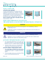
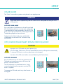
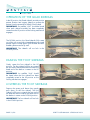
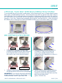
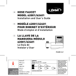
1
the low bed specialist
The SPIRIT™ Ultra Low Bed
USER MANUAL
It is the duty of all staff who handle the SPIRIT™
bed to read these:Guidance Notes
for Safe Use
Call our help line on 01865-409926
if you need advice or further instruction
SPIRIT™ USER MANUAL - VERSION 01-2013
PAGE 1/20
Intended Use
The Spirit™ Bed is intended for low to moderately acute patients in the medical and/or surgical area of
the hospital. The Spirit™ Bed is also intended for use as a general-purpose variable height hospital bed for
general care, post-operative, and general medicine wards.
Standard Conventions Used in this Manual
This manual includes information essential to the safety of the patient, personnel and equipment during the
normal operation of the Spirit™ Bed. Before operating the Spirit™ Bed be sure you read and understood
the contents of this manual. It is important that you use this equipment in accordance with the procedures
outlined in this manual . As you read through this manual be alert to the three signal words.
DANGER Information appearing under the DANGER caption concerns the protection
of personnel from the immediate and imminent hazards that, if not avoided, will result in
immediate, serious personal injury or loss of life in addition to equipment damage.
WARNING Information appearing under the WARNING caption concerns the protection of
personnel from potential hazards that can result in personal injury or loss of life in addition to
equipment damage.
CAUTION Information appearing under the CAUTION caption concerns the protection
of personnel from potential hazards that can result in minor personal injury or equipment
damage.
IMPORTANT ELECTRICAL SAFEGUARDS
DANGER
•
Plug the three prong electrical cord ONLY into a properly grounded 230 VAC, 50 cycle outlet.
•
DO NOT use an extension cord.
•
DO NOT permit the cord, wall outlet to become wet.
•
DO NOT operate the bed if the cord or outlet is damaged.
•
DO NOT operate the bed if any motor has malfunctioned or is damaged in any manner.
During routine bed cleaning, always unplug the three-prong plug from grounded outlet.
DO NOT roll the bed over the power cord. DO NOT entangle the cord on other objects. A
pinched electric cord is dangerous and can become damaged. Be aware of the power cord
location especially when moving the bed.
AUXILIARY BATTERY
NOTE
PAGE 2/20
The battery is continuously charged as long as the bed’s power supply is plugged into a 230 VAC wall outlet.
SPIRIT™ USER MANUAL - VERSION 01-2013
SPIRIT
the low bed
IMPORTANT MECHANICAL SAFEGUARDS
WARNING
DO NOT stand on the bed or concentrate weight on a single fiberglass deck panel.
DO NOT use the bed without a mattress at least 4” (100mm) thick and of recommended
dimensions.
MATTRESS SPECIFICATIONS
A mattress is not included with this bed. It is highly recommended that you use a 35.5”
(900mm) wide mattress that is designed to conform to the bed length of 80” (2032mm).
Possible patient ENTRAPMENT Hazard if using non-specified mattress, patient entrapment may
result in an injury. Use only a mattress of recommended specifications with this bed.
• DO NOT use without a special mattress specifically designed to bend and conform to the shape of the bed.
• DO NOT use a water filled or gel filled mattress on this bed.
GENERAL PRECAUTIONS
• Do not use headboards or footboards from other manufacturers.
• Ensure all deck hinges are properly aligned before raising head or knee sections.
• Ensure that the headboard and footboard are properly attached to the frame.
• This bed is rated to 35 stone / 227kg. DO NOT overload the bed. The combined weigh of patients, visitors, mattress and bedding must NOT exceed 35 stone / 227kg.
The maximum load on either side rail is 12 stone / 77kg.
At the installation
The person supplying and setting up the bed will show staff how it operates.
All staff that may come into contact with the bed whether nurses, cleaners or porters will need to
understand how the bed operates.
A further training session may be required for the above standard to be met and in order to
consolidate staff competence.
REMEMBER:
Training in the use of equipment is a legal requirement
The prerequisites for using the Spirit Ultra Low bed are that it has been electrically
tested and that the person operating it has had instruction in its use. The bed must
also have an up-to-date hospital inspection record.
SPIRIT™ USER MANUAL - VERSION 01-2013
PAGE 3/20
WARNING
Familiarise yourself with the various functions.
Care should be taken that there is no wall - mounted obstruction to prevent the bed moving
vertically.
Ensure that nothing can get trapped underneath the bed when it is lowered.
(Examples: slippers / pillows / walking sticks etc.)
It is essential that the power cable does not get trapped between moving parts. Check before
lowering the bed.
DO NOT allow patients to fall on the bed.
DO NOT Jump on the bed.
Each of the preceding impacts can permanently damage either Hi/Lo motor resulting in an
inoperable bed. In the case of an inoperable bed due to a damaged Hi /Lo motor remove the
bed from service and replace the Hi/Lo motor immediately. If left unattended, a damaged Hi/
Lo motor could result in patient injury.
ONLY use original manufacturers replacement parts
PAGE 4/20
SPIRIT™ USER MANUAL - VERSION 01-2013
SPIRIT
the low bed
Bed Positioning
Bed Elevation - HI-Lo Function
To raise the bed, press the BED UP arrow on the staff
control pad. See DIA 10. Release the button when the
desired level is reached. See DIA 11
DIA 10
DIA 11
DIA 12
DIA 13
DIA 14
DIA 15
DIA 16
DIA 17
DIA 18
DIA 19
DIA 20
DIA 21
To lower the bed, press BED DOWN arrow on the staff
control pad. See DIA 12. Release the button when the
desired level is reached. See DIA 13
Head Elevation - Head Motor Function
To raise the head section of the bed, press the HEAD UP
arrow on the staff control pad. See DIA 14. Release the
button when the desired level is reached. See DIA 15
To lower the head section of the bed, press the HEAD
DOWN arrow on the staff control pad. See DIA 16.
Release the button when the desired level is reached.
See DIA 17
Knee Elevation - Foot Motor Function
To raise the Knee section of the bed, press the KNEE UP
arrow on the staff control pad. See DIA 18. Release the
button when the desired level is reached. See DIA 19
To lower the Knee section of the bed, press the KNEE
DOWN arrow on the staff control pad. See DIA 20.
Release the button when the desired level is reached.
See DIA 21
SPIRIT™ USER MANUAL - VERSION 01-2013
PAGE 5/20
Auto Contour
Activate Auto Contour
In order to prevent patients from sliding towards the
footboard as the head section is elevated, it may be
beneficial to use the auto contour function. This function
will automatically raise/lower the knee section whenever
the head section is raised or lowered (DIA 22). To
activate auto contour, simply press the CONTOUR
button at the bottom right corner of the staff control pad
(DIA 23). When the green light is illuminated, the auto
contour function is active.
DIA 22
DIA 23
Staff and Emergency Functions
TreNdelenburg and Reverse Trendelenburg Operation
CAUTION
Patient discomfort may result from normal operation of the Trendelenburg or Reverse
Trendelenburg function.
Trendelenburg and Reverse Trendelenburg modes should only be used on the advice of a
medical practitioner.
WARNING
The Spirit™ bed may shift during Trendelenburg or Reverse Trendelenburg activation.
Tredelenburg or Reverse Trendelenburg must be operated ONLY after the bed has been
stabilized in the Central Lock & Steer LOCK position.
Activate Trendelenburg Mode
1. Press and hold the TREND button on the staff control
pad. Release the button once the desired bed angle
between 0º and 15º is reached. See DIA 24 and 25
2. To return the bed to level, press and hold the REV
TREND button until the bed automatically stops.
DIA 24
DIA 25
DIA 26
DIA 27
Activate Reverse Trendelenburg Mode
1. Press and hold the rev. TREND button on the staff
control pad. Release the button once the desired bed
angle between 0º and 13º is reached. See DIA 26
and 27
2. To return the bed to level, press and hold the TREND
button until the bed automatically stops.
PAGE 6/20
SPIRIT™ USER MANUAL - VERSION 01-2013
SPIRIT
the low bed
Chair Mode
The “Chair” function allows patients to be placed in an upright postion.
WARNING
Chair mode must be operated only after the Central Lock & Steer pedal has been put in the
LOCK position.
Activate Chair Mode
Press and hold the CHAIR button on the staff control pad
(DIA 28). Release the button once the chair configuration
is reached (bed will stop automatically) See DAI 29. The
green `Chair’ light will illuminate once the proper Reverse
Trendelenburg angle has been achieved.
To deactivate the Chair Mode, press and hold the
CHAIR button until the bed is flat. The bed will stop
automatically.
DIA 28
DIA 29
CPR (Cardiopulmonary Resuscitation) Mode
CAUTION
Improper use of CPR mode may cause patient injury.
Once activated, CPR function will lower head and knee sections to flat position automatically.
To interrupt CPR function, touch any other button on the keypad.
Activation of the CPR control allows one-touch flattening of all bed surfaces.
Activate CPR Mode
Press the CPR button on the staff control pad one time.
The head section and knee section will lower to flat
position. See DIA 30 and 31.
The CPR mode does not need deactivation. Simply
resume head and knee-foot operation once the CPR
action is complete.
DIA 30
DIA 31
To Interrupt the CPR mode, touch any other function on
the keypad.
SPIRIT™ USER MANUAL - VERSION 01-2013
PAGE 7/20
Patient Lockouts
Activate Individual Function Lockouts
Patient Lock-out restricts the patient from activating various bed
features via the quad rail control pad. The degree of restriction
depends on the lock out option selected.
Staff may choose to lock patients access to one, two, or all three
bed functions. To restrict a function, press the “PATIENT LOCK”
button under that particular function (see DIA 32). The lock icon
will illuminate when the function is locked-out for the patient.
To unlock, press the same button again. When the light is not
illuminated, the patient has access to that function.
DIA 32
NOTE: When patient functions have been locked, the
staff footboard control pad remains active.
Activate Total Lock-out
To completely restrict access to all bed functions from all control
points (staff and patient controls), use the total lock-out function.
Press and hold all three lock-out buttons at the same time (DIA
33). All functions on the staff footboard control pad and all
patient controls are unavailable. Total lock-out is active when all
three lock-out buttons flash sequentially.
DIA 33
To deactivate the total lock-out feature, repeat the process by
pressing and holding all three lock-out buttons at the same time.
WARNING
When left unattended, the bed should be lowered to its lowest position with the ”Bed
Elevation” function locked-out in order to reduce the risk of patient injury.
PAGE 8/20
SPIRIT™ USER MANUAL - VERSION 01-2013
SPIRIT
3.5.3
Spirit™ & Spirit Plus™ Power Status Indicator
the low bed
The enhanced footboard staff control on the Spirit Select™ is equipped with an
Spirit™ Power
Status
Indicator
integrated power
status indicator.
This cluster of 3 discrete icons indicate the realtime status of power available to operate the bed. The icons will illuminate
respectivestaff
of thecontrol
source ofon
power,
operationnecessary
of the battery bed
chargingfunctions
circuit, and
The enhanced footboard
thetheSpirit
the level of battery power.
Select™ is equippedThe
with
an integrated power status are performed to extend
battery is continuously charged when connected to the CB10 control box and
indicator. This cluster
of
3
icons
indicate
the If the
battery
power
long
the bed isdiscrete
plugged into
an AC
power outlet.
battery voltage
dropsas
below
realtime status of power
available
to operate
the bed.disrupted
as possible
and discharge
ensure
18VDC,
battery power
will be automatically
to prevent further
which could
impact theofbattery’s
ability toof
fully recharge.
When the bedfunctions
is plugged
The icons will illuminate
respective
the source
emergency
back into an AC power outlet, battery power will be automatically restored.
power, the operation
of the battery charging circuit, remain available when
Indicator
LED is Solid GREEN
and the level of battery
power.
needed.
Bed is connected to an AC power outlet and operating on AC power. The battery is connected to the CB10 control
The battery is continuously
when
box and ischarged
fully charged.
Bed connected
is ready to operate on battery power if required. This is the optimum operating
for the
the bed.
to the CB10 control condition
box and
bed is plugged into Indicator LED is Flashing RED
Indicator
is Flashing
GREEN
an AC power outlet.
If the LED
battery
voltage
drops Bed is disconnected from an AC power outlet and
Bed ispower
connected
to an
power outlet and operating
on AC operating
power. The battery
is connected
to theAlthough
CB10 controlthe
below 18VDC, battery
will
beACautomatically
has been
on battery
power.
box but is currently recharging.
disrupted to prevent further discharge which could battery is connected to the CB10 control box, it has
is Alternating
and RED
impact the battery’sIndicator
ability toLED
fully
recharge. Flashing
When GREEN
exhausted
its battery power. Reconnect bed to an AC
IMPORTANT:
Bed
may
not
reliably
operate
on
battery
the bed is plugged back into an AC power outlet, power power
outletif required.
as soon as possible and allow battery
Bedautomatically
is connected to anrestored.
AC power outlet and operating
on AC for
power.
The battery is connected to the CB10 control
battery power will be
to charge
24hr.
box but not holding proper charge. Service bed and/or replace battery immediately.
IMPORTANT: At this point, reliable bed operation
OR
Indicator LED is
Solid
GREEN
cannot
be battery
guaranteed
although
somefor 24hr.
bed
The battery is not connected to the CB10 control
box. Connect
to CB10 and allow
battery to charge
Bed is connected Indicator
to an AC
power
outlet
and
functionality
may
still
be
available.
Exercise
caution
LED is Solid RED
operating on AC power.
The battery
is AC
connected
operating
bed as
theThe
bed
williscease
operation
Bed is disconnected
from an
power outlet and
is operatingthe
on battery
power.
battery
connected
to the
boxfully
and has
not yet exhausted
available warning.
battery power. Bed is OK to operate on battery power but
to the CB10 control CB10
boxcontrol
and is
charged.
Bed is thewithout
should bepower
connected
to an AC power
outlet
ready to operate onitbattery
if required.
This
is as soon as is possible to recharge the battery.
IMPORTANT:
Exercise
caution
the bed on battery power. Ensure that only vital and necessary bed
the optimum operating
condition
for the
bed.when operatingNo
Indicator
functions are performed to extend battery power as long
as possible andLED
ensureillumination
emergency functions remain
available when needed.
IMPORTANT: Bed may NOT operate.
Indicator LED is
Flashing GREEN
Indicator LED is Flashing RED
The bed has been disconnected from an AC power
Bed is connected to an
power outlet
BedAC
is disconnected
fromand
an ACoperating
power outlet and has been operating on battery power. Although the battery is
outlet and the battery is disconnected from the CB10
connectedistoconnected
the CB10 control
has exhausted its battery power. Reconnect bed to an AC power outlet as soon
on AC power. The battery
to box,
the itCB10
control box. Reconnect bed to an AC power outlet
as
possible
and
allow
battery
to
charge
for
24hr.
control box but is currently recharging.
andcannot
allow
toalthough
chargesome
for bed
24hr.
IMPORTANT: At this point, reliable bed operation
be battery
guaranteed
functionality may still
be available. Exercise caution operating the bedor
as the bed will cease operation without warning.
Indicator LED is Alternating Flashing
The bed has a faulty connection or component
GREEN and REDNo Indicator LED illumination
IMPORTANT: Bed may NOT operate.
(CB09 control box, CB10 control box, battery, and/
IMPORTANT: BedThemay
notbeen
reliably
operate
bed has
disconnected
from an on
AC power outlet and the battery is disconnected from the CB10 control box.
connection cable). Confirm all connections and
battery power if required.
Bedto is
anallowor
Reconnect bed
an connected
AC power outlettoand
battery to charge for 24hr.
begin
troubleshooting potentially faulty components.
OR operating on AC power. The
AC power outlet and
The
bed
has
a
faulty
connection
or
component
(CB09
control
box, CB10 control box, battery, and/or connection
battery is connected to the CB10 control box but not or
cable). Confirm all connections and begin troubleshooting potentially faulty components.
holding proper charge. Service bed and/or replace The bed has been disconnected from an AC power
OR
battery immediately.The bed has been disconnected from an AC power
outlet
battery
been disengaged
automatically
outletand
and thethe
battery
has been has
automatically
from
the
battery
circuit
because
the
voltage
has
dropped
below
18VDC.
Reconnect
bed
to
an
AC
power
outlet
and allowthe
disengaged
from
the
battery
circuit
because
OR
battery to charge for 24hr.
The battery is not connected to the CB10 control voltage has dropped below 18VDC. Reconnect bed
ACa power
outlet
andwhen
allow
In-house
testing
has demonstrated
new back-up
battery,
fully charged, has sufficient
box. Connect battery to CB10 and
allow
battery
to to anthat
power to deliver the equivalent of approximately 5 CPR cycles with a patient weight of 250 lbs.
battery
to
charge
for
24hr.
charge for 24hr.
Battery power discharge rate depends upon factors such as patient weight, age of battery, ambient
temperature and humidity, and
the number of charge/discharge cycles the battery has been
NOTE:
Note:
heavier the patient, the faster battery power will be exhausted
Indicator LED is Solid REDsubjected to. For example, the
In-house testing has demonstrated that a new back-up battery,
during battery powered bed operation. Conversely, the lighter the patient, battery power may
whenpowered
fully charged,
has sufficient power to deliver the equivalent
Bed is disconnected from an AC power
outlet
and of
is battery
offer a longer
duration
bed operation.
of
approximately
5
CPR
20 Stone
operating on battery
power.
battery
is connected © Carroll Hospital Group Inc. cycles with a patient weight of
1-70-001-H
UserThe
Manual
- Spirit™ Bed
Page 47 of 120
(120kgs)
to the CB10 control box and has not yet exhausted
power discharge rate depends upon factors such
the available battery power. Bed is OK to operate Battery
as patient weight, age of battery, ambient temperature and
on battery power but it should be connected to an humidity, and the number of charge/discharge cycles the battery
AC power outlet as soon as is possible to recharge has been subjected to. For example, the heavier the patient, the
faster battery power will be exhausted during battery powered
the battery.
bed operation. Conversely, the lighter the patient, battery power
IMPORTANT: Exercise caution when operating may offer a longer duration of battery powered bed operation.
the bed on battery power. Ensure that only vital and
SPIRIT™ USER MANUAL - VERSION 01-2013
PAGE 9/20
Patient Quad Rail Control Pad
Head Elevation function
To raise the head section of the bed, press the Head UP arrow, release the button when the desired level is
reached.
To lower the head section of the bed, press the HEAD Down arrow, release button when the desired level
is reached.
Knee Elevation Function
To raise the knee section of the bed, press the KNEE UP arrow, release button when the desired level is
reached.
To lower the knee section of the bed, press the KNEE DOWN arrow, release button when the desire level
is reached.
CAUTION
It is recommended that you de-activate auto contour on the staff control pad, when patient has
full control of head and foot profile functions.
PAGE 10/20
SPIRIT™ USER MANUAL - VERSION 01-2013
SPIRIT
the low bed
Quad-rail staff control pad
Head Profile Elevation Function
To raise the head section of the bed, press the HEAD UP arrow, release the button when the desired level is
reached.
To lower the head section of the bed, press the HEAD DOWN arrow, release button when the desired level
is reached.
Knee Profile Elevation Function
To raise the knee section of the bed, press the KNEE UP arrow, release button when the desired level is
reached.
To lower the knee section of the bed, press the KNEE DOWN arrow, release button when the desired level
is reached.
BeD High/Low Elevation Function
To raise the bed, press the BED UP arrow, release button when the desired level is reached.
To lower the bed, press BED DOWN arrow, release button when the desire level is reached.
SPIRIT™ USER MANUAL - VERSION 01-2013
PAGE 11/20
3.14.4
3.14.4 Quad
QuadSiderails
Siderails
3.14.4 Quad Siderails
Your
YourSpirit
SpiritPlus™
Plus™or
orSpirit
SpiritSelect™
Select™bed
bedcomes
comeswith
withmoulded
mouldedplastic
plasticQuad
Quadsiderails
siderailsas
asstandard
standardequipment.
equipment.
Your Spirit Plus™ or Spirit Select™ bed comes with moulded plastic Quad siderails as standard equipment.
Operation
Operationof
ofthe
theQuad
QuadSiderails
Siderails
Operation of the Quad Siderails
ItItisisimportant
importantthat
thatcaregivers
caregiversknow
knowhow
howtotooperate
operatethe
theQuad
Quadsiderails
siderailssafely.
safely. The
TheQuad
Quadsiderails
siderailslock
lockinin
Itthe
is UP
important
that
caregivers
know
how
to
operate
the
Quad
siderails
safely.
The
Quad
siderails
lock
in
the
position
and
enables
patient
ingress,
egress,
and
transfer
in
the
DOWN
position.
UP position and enables patient ingress, egress, and transfer in the DOWN position.
the UP position and enables patient ingress, egress, and transfer in the DOWN position.
In
Inthe
theUP
UPposition,
position,the
theQuad
Quadsiderails
siderailsprovide
provide
In
the
UP
position,
the
Quad
siderails
In
the
UP
position,
the
Quad
siderails
providepositive
positive
patient
location
and
support
helping
toto
positive patient location and supportprovide
helping
patient
location
and
support
helping
to
protect
positive
patient
location
and
support
helping
to the
protect
protectthe
thepatient
patientfrom
fromthe
thepotential
potentialofoffalling
falling
patient
from
the potential
of falling
from
bed.
protect
the
patient
from the
potential
of the
falling
from
bed.
fromthe
the
bed.
from
the
bed.
IMPORTANT: An
Anaudible
audible“click”
“click”should
shouldbebe
heard
IMPORTANT:
IMPORTANT:
An Siderails
audible
“click”
should
beheard
heard
3.14.4
Quad
when
each
siderail
assembly
has
been
completely
IMPORTANT:
An audible
“click”
should
be heard
when
siderail
assembly
has
been
wheneach
each
siderail
assembly
haslocking
beencompletely
completely
rotated
intosiderail
the
UP
position
asas
the
mechanism
when
each
assembly
has
been
completely
rotated
into
the
UP
position
the
locking
rotated
into
the UP
position
as thebed
locking
Your
Spirit
Plus™
or Spirit
Select™
comes with moulded plastic Quad siderails as standard equipment.
engages.
rotated
into engages.
the
UP position as the locking
mechanism
mechanism
engages.
mechanism engages.
Operation of the Quad Siderails
Operation of the Quad Siderails
It isDOWN
important that caregivers
know how
to operate the Quad siderails safely. The Quad siderails lock in
The
TheDOWN
DOWNposition,
position,
the
Quad
siderails
fully
rotate
The
position,the
theQuad
Quadsiderails
siderailsfully
fullyrotate
rotate
the
UP
position
and
enables
patient
ingress,
egress, and transfer in the DOWN position.
The
DOWN
position,
the
Quad
siderails
fully
rotate
out
of
the
way
to
provide
unimpeded
and
outof
ofthe
theway
waytotoprovide
provideunimpeded
unimpededand
andunassisted
out
out
of the
way
to provide
unimpeded
and
unassisted
patient
ingress
totoand
from
unassisted
patient
ingress
andegress
egress
from
the
In
the
UP
position,
theegress
Quad
siderails
provide
patient
ingress
to and
from
the bed
andthe
also
unassisted
patient
ingress
to
and
egress
from
the
bed
and
also
enables
patient
transfer
by
staff.
bed
and
also
enables
patient
transfer
by
staff.
positive
patient
location
and
support
helping
to
enables patient transfer by staff.
bed
andthe
alsopatient
enables
patient
transfer by
staff.
protect
from
thewill
potential
oflock
falling
IMPORTANT:
not
lock
in
IMPORTANT:
Thesiderails
siderails
will
in the
IMPORTANT:The
The
siderails
will
notnot
lock
inthe
the
from
the
bed.
IMPORTANT:
The
siderails
will
not
lock
in
the
DOWN
DOWN
position.
DOWNposition.
position.
DOWN
position. An audible “click” should be heard
IMPORTANT:
when each siderail assembly has been completely
rotated into the UP position as the locking
mechanism engages.
Raising
Raisingthe
theFoot
FootSiderails
Siderails
Raising
the
Foot Siderails
Raising the Foot Siderails
Gently
Gentlyrotate
rotatethe
thefoot
footsiderail
siderailtotothe
theUP
UP
The
DOWN
position,
the
Quad
siderails
Gently
rotate
the
foot
siderail
to UP
the fully
UP rotate
Gently
rotate
the
foot
siderail
to
the
position.
position. The
Thefoot
footsiderail
siderailwill
willfirst
firstarc
arc
out
of
the
way
to
provide
unimpeded
and
position.
The
foot
siderail
will
first
arc
toward
position.
The
foot
siderail
arc
toward
foot
end
ofofthe
bed
then
towardthe
the
foot
end
thewill
bedfirst
then
unassisted
patient
ingress
to
and
egress
from the
the
foot
endfoot
ofthe
the
bed
then
back
towards
the
toward
the
end
of
the
bed
then
back
towards
head
end
of
the
bed
back towards the head end of the bedas
as
bed
and
also
enables
patient
transfer
byUP
staff.
endto
of the
bed
as
it rotates
to the
back
towards
the
head
end
of the
bed
as
ithead
UP
position.
itrotates
rotates
tothe
the
UP
position.
position.
itIMPORTANT:
rotates to the UP
position.
The
siderails
will should
not lock in the
IMPORTANT:
audible
“click”
IMPORTANT:An
An
audible
“click”
should
IMPORTANT:
An
audible
“click”
should
DOWN
position.
IMPORTANT:
An
audible
“click”has
should
be
heard
when
the
foot
siderail
been
be
heard
when
the
foot
siderail
has
been
be heard when the foot siderail has
been
be
heard when
thetoto
foot
siderail
has been
completely
raised
the
UP
position
as
completely
raised
the
UP
position
as
completely raised to the UP position as the
completely
raised
to theengages.
UP position as
the
mechanism
thelocking
locking
mechanism
engages.
locking
mechanism
engages.
the locking mechanism engages.
Lowering
Loweringthe
theFoot
FootSiderails
Siderails
Lowering
the
Foot
Siderails
Raising
the
Foot
Siderails
Lowering the
Foot
Siderails
Depress
Depressthe
thegreen
greenpush
pushbutton
buttonthen
then
Depress
the
green
push
button
then
gently
push
down
on
the
foot
siderail.
Gently
rotate
the
foot
siderail
to
the UP
gently
push
down
on
the
foot
siderail.
Depress
thedown
green
push
button
then the
gently
gently
push
on
the
foot
siderail.
The
foot
siderail
will
first
arc
towards
position.
The foot
willtowards
first arcthe
The foot
siderail
willsiderail
first arc
push
down
on
the
foot
siderail.
The
foot
The
foot
siderail
will
first
arc
towards
foot
end
of
the
bed
back
towards
toward
the
foot
endthen
of the
bed
then the
foot
end
of
the
bed
then
back
towards
siderail
will
first
arcthen
towards
the
foot to
end of
foot
end
of
the
bed
back
towards
the
end
ofof
the
bed
as
back
towards
the
head
ofrotates
the bed
thehead
head
end
the
bedend
asitthe
it
rotates
toas of
the
bed
then
back
towards
head
end
head
end
of
the
bed
as
it
rotates
to
the
DOWN
position.
it
rotates
toposition.
the UP position.
the
DOWN
the
bed
as position.
it rotates to the DOWN position.
the
DOWN
IMPORTANT:
foot
siderails
will
not
IMPORTANT:
An
“click”will
should
IMPORTANT:The
Theaudible
footsiderails
siderails
will
notlock
IMPORTANT:
The
foot
not
IMPORTANT:
The
foot
siderails
will
not
lock
in
the
DOWN
position.
be
heard
when
the
foot
siderail
has
been
lock
in
the
DOWN
position.
in the DOWN position.
lock
in the DOWN
completely
raised position.
to the UP position as
the locking mechanism engages.
Lowering the Foot Siderails
1-70-001-H
User
Manual
- -Spirit™
1-70-001-H
User
Manual
Spirit™
Bed
Depress
the
green
pushBed
button
1-70-001-H User Manual - Spirit™ Bed
©©Carroll
Page
CarrollHospital
HospitalGroup
GroupInc.
Inc.
Page67
67ofof120
120
then
© Carroll Hospital Group Inc.
Page 67 of 120
gently push down on the foot siderail.
PAGE
12/20
SPIRIT™ USER MANUAL - VERSION 01-2013
The foot
siderail will first arc towards the
foot end of the bed then back towards
the head end of the bed as it rotates to
SPIRIT
the low bed
Raising
the
Siderails
Raising
the Head
Head
Raising
the Siderails
Head Siderails
Gently
rotate the
head siderail
to
UP
Gently
the
siderail
to the
the
UP UP
Gently rotate
rotate
thehead
head
siderail
toarc
the
position.
The
head
siderail
will
first
position.
The
head
siderail
will will
first arc
position.
The
head
siderail
first
arc
toward
the
head
end
of
the
bed
then
back
toward
the
head
end
of
the
bed
then
back
toward the
head
endofofthe
thebed
bedasthen
back
towards
the
foot
end
it
towards
the
foot
end
of
the
bed
as
itit rotates
towards
the
foot
end
of
the
bed
as
rotates
to
the
rotates
to position.
the UP
UP position.
position.
to the UP
IMPORTANT:
“click”
should
be
IMPORTANT: An
Anaudible
audible
“click”
should
IMPORTANT:
An
audible
“click”
should
be
heard
when
the
head
siderail
has
been
be heard
the head
siderail
has been
heard
whenwhen
the head
siderail
has been
completely
completely raised
raisedto
theUP
UPposition
positionas
the
completely
raised
totothe
the
UP
position
asasthe
the
locking
mechanism
engages.
lockingmechanism
mechanism engages.
engages.
locking
Lowering
Head
Siderails
Lowering
the
Head
Siderails
Raisingthe
the
Head
Siderails
Depress
the green
push button
then
Depress
Depress the
the green
greenpush
pushbutton
buttonthen
then gently
gently
push
on the
siderail.
gently
push down
down
the head
head
siderail.
push down
on theonhead
siderail.
The head
The
head
siderail
will
first
arc
towards
the
The
head
siderail
will
first
arc
towards
the of
siderail will first arc towards the head end
head
end
of
the
bed
then
back
towards
head
endthen
of the
bed
then back
towards
the bed
back
towards
the foot
end of the
the
foot end
of
bed
as
to
the
of the
the
bedDOWN
as it
it rotates
rotates
to
bedfoot
as itend
rotates
to the
position.
the
DOWN
position.
the
DOWN
position.
IMPORTANT: The head siderails will not
IMPORTANT:
The
head
lock in the DOWN
IMPORTANT:
The position.
head siderails
siderails will
will not
not
lock
in
the
DOWN
position.
lock in the DOWN position.
Integrated
Features
Integrated
Features
BED operation
Staff
Siderail
Central
Lock Controls
and Steer System
Staff
Siderail
Controls
Neutral
Angle
Gauges
Angle
Gauges
Mode used only to manoeuvre the All casters swivel and roll
All
four
siderails have
integrated
angle gauges:
All
four
haveThis
integrated
bed
in asiderails
tight area.
mode angle gauges:
•• The
head
angle
allows
the bed
move forward,
The
headtosiderail
siderail
angle gauge
gauge displays
displays the
the
angle
of
the
head
section
of
the
backward
or of
sideways.
angle
the head section of the mattress
mattress
deck.
deck.
SPIRIT™
USER MANUAL
- VERSION
01-2013
•• The
Head
The foot
foot siderail
siderail angle
angle gauge
gauge displays
displays the
the
Head Siderail
Siderail
Trendelenburg
or
reverse
Trendelenburg
angle
Angle
Trendelenburg or reverse Trendelenburg angle
Angle Gauge
Gauge
DIA 36
DIA 35
DIA 34
The
control
The head
head siderails
siderails incorporate
incorporate integrated
integrated staff
staffWARNING
control that
that offers
offers staff
staff
control
of
basic
bed
operations:
control of basic bed operations:
•• Head
UP/DOWN,
HeadUnintended
UP/DOWN,bed movement may occur if bed is left in either of the mobilized positions, “STEER”
•• Knee/Foot
UP/DOWN
or “NEUTRAL”.
Knee/Foot
UP/DOWN
•• Bed
UP/DOWN
Never leave the bed unattended in either the “STEER” or “NEUTRAL” positions.
Bed UP/DOWN
IMPORTANT:
operation
from
this
control
is
when
patient
Do Bed
not move
the bed
until
mobilization
system
hasthe
been
activated.
IMPORTANT:
Bed
operation
from
thisthe
control
is disabled
disabled
when
the
patient
lock-outs
are
activated.
lock-outs are activated.
MODEFUNCTIONPEDAL POSITION
Lock
Patient
Siderail
Patient
Siderail Controls
Controls
Typical mode used to stabilize the Casters DO NOT
The
head siderails
incorporate
integrated patient control
that
The
incorporate
control
that offers
offers patient
patient
bed head
from siderails
shifting. This
mode integrated patient
swivel
or roll
control
of
basic
bed
operations:
control
of
basic
bed
operations:
prevents the bed from moving
•• Head
UP/DOWN,
forward,
backward
or sideways.
Head
UP/DOWN,
•• Knee/Foot
UP/DOWN
Knee/Foot UP/DOWN
STEER
•• Nurse
Call
Nursewhen
Call feature
feature
Mode used
attempting to Two head end casters swivel;
IMPORTANT:
Bed
operation
from
control is
when
IMPORTANT:
operation
from this
this
is disabled
disabled
when the
the patient
patient
steer the bed inBed
a desired
direction.
control
Two foot
end casters
lock-outs
are
activated.
lock-outs
are
activated.
All caster wheels can still rotate, DO NOT swivel;
IMPORTANT:
The
Call
if
patient
enabling the bed
to Nurse
move forward
remains
Allactive
casters
IMPORTANT:
The
Nurse
Call feature
feature
remains
active
if roll
patient lock-outs
lock-outs
have
been
activated.
or
backward.
have been activated.
PAGE 13/20
Foot
Foot Siderail
Siderail
Angle
Gauge
Angle Gauge
Mobilization
Mobilization
The bed is mobile in either the “NEUTRAL” or “STEER” modes. Use either of these modes depending on the
situation, when bed mobility is needed.
Activate Steer Mode
1. Fully depress the right side of the central lock &
Steer pedal at either end of the bed. See DIA 36.
2. Slide the bed sideways, in a back and fourth
motion, at the foot end of the bed until the
steering casters are engaged. See DIA 37.
NOTE: When the ”NEUTRAL” mode is activated
properly, the bed should move freely without
any unusual noises. If any clicking noises are
present in the neutral mode, stop and check
that the pedal is level. Adjust, if necessary.
DIA 37
DIA 38
Activate Neutral Mode
1. Press or lift the pedal with your foot until the pedal
is level.
Stabilization
DIA 39
The bed is stable in the ”LOCK” mode. Use this mode whenever the bed is left unattended or when the bed
needs to remain stable.
Activate Lock Mode
1. Fully depress the left side of the Central Lock &
Steer pedal at either end of the bed. See DIA 39
DIA 40
PAGE 14/20
SPIRIT™ USER MANUAL - VERSION 01-2013
SPIRIT
the low bed
Optional
“Easy
Bed”
Extension/Retraction
System
3.12
3.12Optional
3.12
Optional
3.12Optional
Optional
“Easy
“EasyBed”
“Easy
Bed”
“Easy
Extension/Retraction
Bed”
Extension/Retraction
Bed”Extension/Retraction
Extension/Retraction
System
System
System
System
To accommodate
the
physical
needs
of
taller
patients,
while
maintaining
the
easy
ofbed
frequent
bed
movement
3.12
Optional
3.12
“Easy
Optional
Bed”
Extension/Retraction
“Easy
Bed”
Extension/Retraction
System
System
To
To
accommodate
accommodate
To To
accommodate
accommodate
thethe
physical
physical
the
needs
the
needs
physical
physical
of of
taller
taller
needs
needs
patients,
patients,
of taller
of taller
while
while
patients,
patients,
maintaining
maintaining
while
while
maintaining
themaintaining
the
easy
easy
of of
the
frequent
frequent
the
easy
easy
of
bed
bed
frequent
ofmovement
frequent
movement
bed
about
movement
about
movement
about
about
about space
confined
healthcare
facilities,
Carroll
Hospital
Group
offers
anBed”
optional
“Easy
Bed”
extension
space
space
confined
confined
space
space
healthcare
healthcare
confined
confined
facilities,
healthcare
facilities,
healthcare
Carroll
Carroll
facilities,
facilities,
Hospital
Hospital
Carroll
Carroll
Group
Group
Hospital
Hospital
offers
offers
Group
an
Group
an
optional
optional
offers
offers
an
“Easy
“Easy
an
optional
optional
Bed”
Bed”
extension
“Easy
extension
“Easy
Bed”
system
extension
system
extension
that
that
system
system
that
that
To accommodate the physical
To accommodate
needs of taller
the patients,
physical needs
while maintaining
of taller patients,
the easy
while
of maintaining
frequent bedthe
movement
easy of frequent
about bed movement about
allows
allows
for
for
easy
allows
easy
allows
and
and
for
rapid
for
easy
rapid
easy
extension/retraction
and
extension/retraction
and
rapid
rapid
extension/retraction
extension/retraction
of
of
thethe
mattress
mattress
ofan
the
ofHospital
deck
the
deck
mattress
mattress
byGroup
by
4 of
inches
4deck
inches
deck
by
(102
(102
by
4 optional
inches
mm)
4 mm)
inches
from
(102
from
(102
80”
mm)
80”
mm)
(2032
(2032
from
from
mm)
80”
mm)
80”
(2032
to to
(2032
mm)
mm)
to tomm) from
system that
allows
for
easy
and
rapid
extension/retraction
the
mattress
deck
by
4
inches
(102
space
confined
healthcare
space
facilities,
confined
Carroll
healthcare
Hospital
facilities,
Group
offers
Carroll
optional
“Easy
offers
Bed”
extension
an
system
“Easy
that
Bed”
extension
system
that
84”
84”
(2134
(2134
84”
mm).
(2134
No
(2134
No
tools
mm).
tools
mm).
areare
No
required
No
required
tools
tools
are
toare
to
perform
required
required
bed
tobed
perform
toare
“Easy
perform
“Easy
Bed”
bed
Bed”
extension/retraction
“Easy
extension/retraction
“Easy
Bed”
extension/retraction
extension/retraction
operations.
operations.
operations.
operations.
allows
formm).
easy
and
rapid
allows
extension/retraction
for
easy
and
rapid
ofperform
the
extension/retraction
mattress
deckrequired
by
of
4bed
inches
the
mattress
(102
mm)
deck
from
by 480”
inches
(2032
(102
mm)
mm)
to
from
80” (2032
mm) to
80” (2032
mm)
to84”
84”
(2134
mm).
No
tools
toBed”
perform
bed
“Easy
Bed”
extension/retraction
84”
(2134
mm).
NoSpirit™
tools
84”
are
(2134
required
mm).
tobeen
No
perform
tools
are
bed
required
“Easy
Bed”
to
perform
extension/retraction
bed
“Easy
Bed”
operations.
extension/retraction
operations.
If
If
your
your
Spirit™
Spirit™
If
your
If
bed
your
bed
has
has
Spirit™
been
been
bed
equipped
bed
has
equipped
has
been
with
equipped
with
equipped
the
the
optional
optional
with
with
the
“Easy
the
“Easy
optional
optional
Bed
Bed
Extension”
“Easy
Extension”
“Easy
Bed
Bed
system,
Extension”
system,
Extension”
the
the
system,
bed
bed
system,
will
will
the
be
be
the
outfitted
bed
outfitted
bed
will
will
be
with
with
be
outfitted
outfitted
withbed will
operations.
If your
Spirit™
bed
haswith
been
equipped
with
the optional
“Easy
Bed
Extension”
system,with
the
If
your
Spirit™
bed
has
been
If an
your
equipped
Spirit™
bedan
has
the
been
optional
equipped
“Easy
Bed
with
Extension”
the
optional
system,
“Easy
the
Bed
bed
Extension”
will
be
outfitted
system,
the
with
bed will be outfitted with
two
two
clamping
clamping
two
knobs
two
clamping
knobs
clamping
and
and
knobs
an
extendable
knobs
extendable
andand
an
foot
extendable
foot
extendable
deck
deck
section
foot
section
foot
deck
of
deck
of
the
section
the
mattress
section
mattress
of the
of
deck
the
deck
mattress
mattress
as
as
shown
shown
deck
deck
below.
as
below.
as
shown
shown
below.
below.
be outfitted
two
clamping
knobs
an
extendable
deck
of as
the
mattress
two with
clamping
knobs
andtwo
an extendable
clamping
knobs
footand
deck
and an
section
extendable
of the foot
mattress
deckfoot
deck
section
as
shown
of thesection
mattress
below. deck
shown
below. deck as shown below.
3.12
3.12Optional
3.12
Optional
3.12Optional
Optional
“Easy
“EasyBed”
“Easy
Bed”
“Easy
Extension/Retraction
Bed”
Extension/Retraction
Bed”Extension/Retraction
Extension/Retraction
System
System
System
System
Clamping Knobs
(viewed
Clamping
from foot
Knobs
endfoot
of(viewed
bed)
foot end
Extendable
of bed) Foot Deck Section
Extendable
Foot Deck Section
Clamping
Knobs
(viewed
from
end from
of bed)
Extendable
Foot Deck Section
ToClamping
To
accommodate
accommodate
To
To
accommodate
accommodate
the
the
physical
physical
the
needs
the
needs
physical
physical
of
of
taller
taller
needs
needs
patients,
patients,
ofend
taller
of bed)
taller
while
while
patients,
patients,
maintaining
maintaining
while
while
maintaining
the
maintaining
the
easy
easy
of
of
the
frequent
frequent
the
easy
easy
of
bed
bed
frequent
of
movement
frequent
movement
bedbed
about
movement
about
movement
about
about
(viewed
(viewed
from
from
(viewed
foot
(viewed
foot
end
from
end
of
from
of
bed)
foot
bed)
foot
end
of
of
bed)
Extendable
Extendable
Foot
Extendable
Foot
Extendable
Deck
Deck
Section
Foot
Section
Foot
Deck
Deck
Section
Section
Clamping
Knobs
Clamping
Knobs
Clamping
Knobs
Knobs
Bed
Extension
Procedure
Bed
Extension
Procedure
space
space
confined
confined
space
space
healthcare
healthcare
confined
confined
facilities,
healthcare
facilities,
healthcare
Carroll
Carroll
facilities,
facilities,
Hospital
Hospital
Carroll
Carroll
Group
Group
Hospital
Hospital
offers
offers
Group
anGroup
an
optional
optional
offers
offers
an
“Easy
“Easy
an
optional
optional
Bed”
Bed”
extension
“Easy
extension
“Easy
Bed”
Bed”
system
extension
system
extension
that
that
system
system
that
that
Bed allows
Extension
Procedure
Bed
BedExtension
Bed
Bed
Extension
Extension
Procedure
Procedure
Procedure
Procedure
allows
forExtension
for
easy
allows
easy
allows
and
and
for
rapid
for
easy
rapid
easy
extension/retraction
and
extension/retraction
and
rapid
rapid
extension/retraction
extension/retraction
of of
thethe
mattress
mattress
of the
ofdeck
the
deck
mattress
mattress
byby
4 inches
4deck
inches
deck
by
(102
(102
by
4 inches
mm)
4 mm)
inches
from
(102
from
(102
80”
mm)
80”
mm)
(2032
(2032
from
from
mm)
80”
mm)
80”
(2032
to to
(2032
mm)
mm)
to to
84”
84”
(2134
(2134
mm).
84”
mm).
84”
(2134
No
(2134
No
tools
mm).
tools
mm).
areare
No
required
No
required
tools
tools
are
toare
to
perform
required
perform
required
bed
tobed
perform
to“Easy
perform
“Easy
Bed”
bed
Bed”
bed
extension/retraction
“Easy
extension/retraction
“Easy
Bed”
Bed”
extension/retraction
extension/retraction
operations.
operations.
operations.
operations.
If If
your
your
Spirit™
Spirit™
If your
Ifbed
your
bed
Spirit™
has
has
Spirit™
been
been
bed
equipped
bed
has
equipped
has
been
been
with
equipped
with
equipped
thethe
optional
optional
with
with
the
“Easy
the
“Easy
optional
optional
Bed
Bed
Extension”
“Easy
Extension”
“Easy
BedBed
system,
Extension”
system,
Extension”
thethe
system,
bed
bed
system,
willwill
the
bebe
the
outfitted
bed
outfitted
bed
willwill
be
with
with
be
outfitted
outfitted
with
with
two
two
clamping
clamping
two
knobs
two
clamping
knobs
clamping
and
and
an
knobs
an
extendable
knobs
extendable
andand
an an
foot
extendable
foot
extendable
deck
deck
section
foot
section
foot
deck
ofdeck
of
the
section
the
mattress
section
mattress
of the
ofdeck
the
deck
mattress
mattress
asas
shown
shown
deck
deck
below.
as
below.
as
shown
shown
below.
below.
Knob clamped
1.
Knob
Knob unclamped and
Knob unclamped
clamped and
contacting retention bracket
contacting retention bracket
1. Elevate bed to comfortable
1. Elevate
working
bedunclamped
height.
tounclamped
comfortable
Unclamp
working
height.
Unclamp bracket
2. Grasp
2. Grasp
by thefootboard
corners as
bracket
shownby the corners as shown
Knob
Knob
and
and
Knob
Knob
unclamped
unclamped
and
andfootboard
Knob
Knob
clamped
clamped
Knob
Knob
clamped
clamped
the footboard bracket slide
the mechanism
footboard
bracket
by
turning
slidebracket
both
mechanism
by bracket
turning
bothsmoothly
above.
Gently and
above.
pullGently
away and
fromsmoothly
the headpull away from the head
retention
retention
bracket
retention
retention
bracket
contacting
contacting
contacting
contacting
knobs counter-clockwiseknobs
until they
counter-clockwise
come to stop on
until they come
stop
on the footboard
of thetobed
until
of the bracket
bed untilslide
the footboard bracket slide
their retention brackets. their retention brackets.
mechanism contacts its mechanical
mechanism stops.
contacts its mechanical stops.
1. 1.
Elevate
Elevate
1.bed
Elevate
tocomfortable
Elevate
to
comfortable
comfortable
bedbed
to comfortable
to
working
comfortable
working
height.
height.
working
working
Unclamp
Unclamp
height.
height.
Unclamp
2.Unclamp
2.
Grasp
Grasp
footboard
footboard
2. 2.
Grasp
Grasp
bracket
footboard
bracket
footboard
byby
the
bracket
the
bracket
corners
corners
by
by
the
asas
the
shown
corners
shown
corners
as
shown
shown
Elevate
bedbed
to1.
working
height
2.
Grasp
footboard
bracket
byasthe
corners as thethe
footboard
footboard
thebracket
the
footboard
bracket
footboard
slide
slide
bracket
mechanism
bracket
mechanism
slide
slide
mechanism
byby
mechanism
turning
turning
both
byboth
by
turning
turning
both
both
above.
above.
Gently
Gently
above.
and
above.
and
smoothly
Gently
smoothly
Gently
and
pull
and
smoothly
pull
away
smoothly
away
from
pull
from
pull
the
away
the
away
head
head
from
from
thethe
head
head
Unclamp
the
footboard
bracket
slide
mechanism
shownabove.
Gently
and
smoothly
pull knobs
knobs
counter-clockwise
counter-clockwise
knobs
knobs
counter-clockwise
counter-clockwise
until
until
they
they
come
until
come
until
to
they
to
stop
they
stop
come
on
come
onto stop
to stop
onof
onthe
of
the
bed
bed
until
ofuntil
the
ofthe
the
the
bed
footboard
bed
footboard
until
until
thebracket
the
footboard
bracket
footboard
slide
slide
bracket
bracket
slide
slide
their
their
retention
retention
their
their
brackets.
retention
brackets.
retention
brackets.
brackets.
mechanism
mechanism
mechanism
contacts
contacts
mechanism
its
its
contacts
mechanical
mechanical
contacts
its
mechanical
stops.
stops.
mechanical
stops.until the by turning
both
knobs
counter-clockwise
until away
from
theitsheadof
thestops.
bed
(viewed
(viewed
from
from
(viewed
foot
(viewed
foot
end
from
end
of
from
of
bed)
foot
bed)
foot
endend
of bed)
of bed)
Extendable
Extendable
Extendable
Foot
Extendable
Deck
Deck
Section
Foot
Section
Foot
Deck
Deck
Section
Section
Clamping
Clamping
Clamping
Knobs
Clamping
Knobs
they
comeKnobs
to
stop
onKnobs
their
retention
brackets.
Foot
footboard
bracket
slidemechanism contacts its Bed
BedExtension
Extension
Bed
Bed
Extension
Extension
Procedure
Procedure
Procedure
Procedure
mechanical stops.
Knob fully clamped (knob
fastener fully engaged)
Knob Knob
fully clamped
not fully (knob
clamped (knobKnob not fully clamped (knob
fastener
fully engaged)
fastener
not fully engaged) fastener not fully engaged)
Unlock footbydeck extension
4. Unlock
pan foot
by grasping
deck extension
the
pan by grasping the
3. Clamp the footboard bracket
3. Clampslide
the mechanism
footboard bracket
by
slide4.mechanism
chrome
and sliding
chrome
the locking
handlemechanism
and sliding the locking mechanism
turning both retention knobs
turning
clockwise
both retention
until hand
knobs
tight.
clockwise
until handle
hand tight.
towards
the patient left side
towards
of the
thebed
patient
to the
left side of the bed to the
Knob
Knob
fully
fully
clamped
clamped
Knob
Knob
fully
(knob
(knob
fully
clamped
clamped
(knob
(knob
IMPORTANT:
Ensure
that
IMPORTANT:
the clamping
Ensure
knob
fastener
that
thenot
clamping
knob
fastener
Knob
Knob
not
not
fully
fully
Knob
clamped
Knob
clamped
not
fully
(knob
(knob
fully
clamped
clamped
(knob
(knob
unlocked
unlocked
unlocked
position
icon) (green, unlocked icon)
fastener
fastener
fully
fully
engaged)
fastener
engaged)
fastener
fully
fully
engaged)
engaged)
extends
through
the retention
extends
hole
through
located
the
retention
the
hole
located
in theposition (green,
fastener
fastener
notin
not
fully
fastener
fully
fastener
engaged)
engaged)
not
not
fully
fully
engaged)
engaged)
footboard bracket channel.
footboard
Typicalbracket
both sides.
channel. Typical both sides.
4.by
4.
Unlock
foot
4.
foot
4.
Unlock
deck
deck
Unlock
extension
foot
extension
foot
deck
deck
pan
extension
pan
extension
by
by
grasping
grasping
panpan
by
thethe
by
grasping
grasping
thethe
3.1-70-001-H
3.
Clamp
Clamp
the
3.
the
footboard
3.
Clamp
footboard
Clamp
the
bracket
the
footboard
bracket
footboard
slide
slide
bracket
mechanism
bracket
mechanism
slide
slide
mechanism
byby
mechanism
byUnlock
User Manual - Spirit™
1-70-001-H
Bed
User Manual - Spirit™
© Carroll
Bed Hospital Group Inc. © Carroll Hospital Group Inc.
Page 61 of 120
Page 61 of 120
chrome
chrome
handle
handle
chrome
chrome
and
and
handle
sliding
sliding
handle
the
and
the
and
locking
sliding
locking
sliding
mechanism
the
mechanism
the
locking
locking
mechanism
mechanism
turning
turning
both
both
turning
retention
turning
retention
both
both
knobs
retention
knobs
retention
clockwise
clockwise
knobs
knobs
until
clockwise
until
clockwise
hand
hand
tight.
until
tight.
until
hand
hand
tight.
tight.
towards
towards
thethe
towards
patient
towards
patient
left
the
left
the
side
patient
side
patient
of of
the
left
the
left
bed
side
bed
side
to
ofto
the
the
ofthe
the
bedbed
to the
to the
IMPORTANT:
IMPORTANT:
IMPORTANT:
IMPORTANT:
Ensure
Ensure
that
that
Ensure
thethe
Ensure
clamping
clamping
that
that
the
knob
the
clamping
knob
clamping
fastener
fastener
knob
knob
fastener
fastener
unlocked
unlocked
position
position
unlocked
unlocked
(green,
(green,
position
position
unlocked
unlocked
(green,
(green,
icon)
icon)
unlocked
unlocked
icon)
icon)
extends
extends
through
through
extends
extends
thethe
through
retention
through
retention
the
hole
the
retention
hole
retention
located
located
hole
inhole
in
the
located
the
located
in the
in the
footboard
footboard
bracket
footboard
bracket
footboard
channel.
channel.
bracket
bracket
Typical
Typical
channel.
channel.
both
both
Typical
sides.
Typical
sides.
both
both
sides.
sides.
Knob
Knob
unclamped
unclamped
and
and
Knob
Knob
unclamped
unclamped
andand
Knob
Knob
clamped
clamped
Knob
Knob
clamped
clamped
1-70-001-H
1-70-001-H
User
1-70-001-H
User
Manual
1-70-001-H
Manual
- Spirit™
User
- Spirit™
User
Manual
Bed
Manual
Bed-contacting
Spirit™
- Spirit™
Bedretention
Bed
©©
Carroll
Carroll
Hospital
Hospital
© Carroll
©
Group
Carroll
Group
Hospital
Inc.
Hospital
Inc. Group
Group
Inc.Inc.
retention
bracket
bracket
retention
retention
bracket
bracket
contacting
contacting
contacting
Page
Page
61 61
of 120
of 120
Page
Page
61 of
61120
of 120
1. 1.
Elevate
Elevate
bed
1.bed
1.
Elevate
to Elevate
to
comfortable
comfortable
bed
bed
to comfortable
to
working
comfortable
working
height.
working
working
Unclamp
Unclamp
height.
height.
2.Unclamp
2.
Grasp
Grasp
footboard
footboard
2. 2.
Grasp
Grasp
bracket
footboard
bracket
footboard
byby
the
bracket
the
bracket
corners
corners
by
by
the
asas
the
shown
corners
shown
corners
as as
shown
shown
3.Clamp
the footboard
bracket
slideheight.
mechanism
byUnclamp
4.
Unlock
foot
deck
extension
pan
by grasping thethe
footboard
footboard
thebracket
the
footboard
bracket
footboard
slide
slide
bracket
mechanism
bracket
mechanism
slide
slide
mechanism
byby
mechanism
turning
turning
both
byboth
by
turning
turning
both
both
above.
above.
Gently
Gently
above.
and
above.
and
smoothly
Gently
smoothly
Gently
and
pull
and
smoothly
pull
away
smoothly
away
from
pull
from
pull
the
away
the
away
head
head
from
from
thethe
head
head
turning
both
retention
knobs
clockwise
until
hand
tight.
the
chrome
handle
and
sliding
the
locking knobs
knobs
counter-clockwise
counter-clockwise
knobs
knobs
counter-clockwise
counter-clockwise
until
until
they
they
come
until
come
until
to
they
to
stop
they
stop
come
on
come
onto stop
to stop
onof
onthe
of
the
bed
bed
until
ofuntil
the
ofthe
the
the
bed
footboard
bed
footboard
until
until
thebracket
the
footboard
bracket
footboard
slide
slide
bracket
bracket
slide
slide
their
their
retention
retention
their
their
brackets.
retention
brackets.
retention
brackets.
brackets.
mechanism
mechanism
mechanism
contacts
contacts
mechanism
itsits
contacts
mechanical
mechanical
contacts
its its
mechanical
stops.
stops.
mechanical
stops.
stops. left side of the mechanism
towards
the patient
IMPORTANT: Ensure that the clamping knob fastener
bed to theunlocked position
extends through the retention hole located in the
(green, unlocked icon)
footboard bracket channel. Typical both sides.
SPIRIT™ USER MANUAL - VERSION 01-2013
Knob
Knob
fully
fully
clamped
clamped
Knob
Knob
fully
(knob
(knob
fully
clamped
clamped
(knob
(knob
Knob
Knob
notnot
fully
fully
Knob
clamped
Knob
clamped
notnot
fully
(knob
(knob
fully
clamped
clamped
(knob
(knob
fastener
fastener
fully
fully
engaged)
fastener
engaged)
fastener
fullyfully
engaged)
engaged)
fastener
fastener
notnot
fully
fastener
fully
fastener
engaged)
engaged)
notnot
fullyfully
engaged)
engaged)
PAGE 15/20
5.
Grasp
the chrome
handle
as
shown
at
right.
Gently
6.
Lock
foot deck
extension
pan by grasping the
Grasp
thechrome
chrome
handleas
asshown
shownatatright.
right.
Gently
and 6.6.Lock
graspingthe
thechrome
chrome
Lockfoot
footdeck
deck
extension
panbybygrasping
5.5.Grasp
the
handle
Gently
and
extension
pan
smoothly
pull
away
from
the
head
end
of
the
bed
until
handle
and
sliding
the
locking
mechanism
towards
and smoothly
pull
away
from
the
head
end
of
the
bed
chrome
handle
and
sliding
smoothly pull away from the head end of the bed until
handle and sliding the locking mechanism towards the locking thefoot
footdeck
deckextension
extensionpan
pancontacts
contactsitsitsmechanical
mechanical
patientright
rightside
sideofofthe
thebed
bedtotothe
thelocked
locked
the
the
patient
until the
foot
deck
extension
pan
contacts
its
the
(red,
mechanism
towards
the patient right side of stops.
position(red,
lockedicon).
icon).
stops.
position
locked
mechanical
the bed
to
the
locked pan
position
5.
5. Grasp
Grasp the
thestops.
chrome
chrome handle
handle as
as shown
shown at
at right.
right. Gently
Gently and
and 6.
grasping the
the chrome
chrome
6. Lock
Lock
foot
foot deck
deck
extension
extension
pan by
by grasping
(red,
locked
icon).
smoothly
smoothly pull
pull away
away from
from the
the head
head end
end of
of the
the bed
bed until
until
handle
handle
and
and
sliding
sliding
the
the
locking
locking
mechanism
mechanism
towards
towards
WARNING
WARNING
the
the foot
foot deck
deck extension
extension pan
pan contacts
contacts its
its mechanical
mechanical
the
the patient
patient right
right side
side of
of the
the bed
bed to
to the
the locked
locked
stops.
stops.
PossiblePATIENT
PATIENTENTRAPMENT
ENTRAPMENTHazard
Hazardcould
couldoccur
occurififthe
themattress
mattressisisnot
notsecurely
securely
Possible
position
position
(red,
(red,
locked
locked
icon).
icon).
located
and
retained
on
the
mattress
deck
by
the
four
corner
mattress
keepers.
located and retained on the mattress deck by the four corner mattress keepers.
WARNING
NEVERperform
performaabed
bedextension/retraction
extension/retraction
withaapatient
patienton
onthe
thebed.
bed.
NEVER
with
NEVER place a patient on the bed if the mattress
is not properly located and retained on
WARNING
WARNING
NEVER place a patient on the bed if the mattress is not properly located and retained on
Possible PATIENT
Hazard
could
themattress
mattressENTRAPMENT
deckby
bythe
thefour
fourcorner
corner
mattresskeepers.
keepers.occur if the mattress is not securely located
the
deck
mattress
Possible
Possible
PATIENT
PATIENT
ENTRAPMENT
Hazard
Hazard
could
occur
occurkeepers.
ifif the
the mattress
mattress
isis not
not securely
securely
and retained
on the
mattressENTRAPMENT
deck by the four
cornercould
mattress
NEVER
perform
a bed
located
located
and
and
retained
retained
on
on
the
the
mattress
mattress
deck
deck
by
by
the
the
four
four
corner
corner
mattress
mattress
keepers.
keepers.
extension/retraction with a patient on theCAUTION
bed. NEVER place a patient on the bed if the mattress
CAUTION
NEVER
NEVER
perform
perform
aa bed
bed
extension/retraction
extension/retraction
with
with
aaby
patient
patient
on
on“lock”
the
the
bed.
bed.mattress keepers.
is not properly
and
retained
on
the
mattress
deck
the
four
corner
Possiblelocated
UNEXPECTED
MOTION
could
occur
theslide
slide
lock
not
the
“lock”
Possible
UNEXPECTED
MOTION
could
occur
ififthe
lock
isisnot
ininthe
positionand
andthe
themattress
mattressdeck
deckisisarticulated
articulatedfrom
thehorizontal
horizontalposition.
position.
position
NEVER
NEVER
place
place
aa patient
patient
on
on the
the
bed
bed ififfrom
the
thethe
mattress
mattress
isis not
not properly
properly located
located and
and retained
retained on
on
When
the
bed
is
in
either
the
extended
or
retracted
position,
the
clamping
knob
When
the
bed
is
in
either
the
extended
or
retracted
position,
the
clamping
knob
the
the mattress
mattress deck
deck by
by the
the four
four corner
corner mattress
mattress keepers.
keepers.
fastenersMUST
MUSTbe
befully
fullyengaged
engagedCAUTION
andthe
theslide
slidelock
lockMUST
MUSTbe
beininthe
the“lock”
“lock”position
positionprior
prior
fasteners
and
placingaapatient
patienton
onthe
thebed
bedand/or
and/orallowing
allowingaapatient
patienttotoreturn
returntotothe
thebed.
bed.
totoplacing
Possible UNEXPECTED MOTION could occur if the slide lock is not in the “lock” position
CAUTION
CAUTION
and the mattress
deck
is articulated
from
the
horizontal
position.
When
theand
bed
Bedretraction
retraction
procedure
isthe
thesame
same
asthe
the
above
exceptthat
that
thefootboard
footboard
bracket
and is in either the
Bed
procedure
is
as
above
except
the
bracket
Possible
Possible
UNEXPECTED
UNEXPECTED
MOTION
MOTION
could
could
occur
occur
if
if
the
the
slide
slide
lock
lock
is
is
not
not
in
in
the
the “lock”
“lock”and the
the
foot
deck
extension
pan
are
pushed
towards
the
head
end
of
the
bed
until
contact
extended
or
retracted
position,
the
clamping
knob
fasteners
MUST
be
fully
engaged
NOTE: the foot deck extension pan are pushed towards the head end of the bed until contact isis
NOTE:
position
position
and
and
the
the
mattress
deck
deckstops.
isis
articulated
articulated
from
from the
the
horizontal
horizontal
position.
position.
made
withbe
their
respective
mechanical
stops.
with
their
mechanical
slide lockmade
MUST
inrespective
themattress
“lock”
position
prior
to placing
a
patient
on the
bed and/or allowing
When
the
theto
bed
bed
in
in either
either the
the extended
extended or
or retracted
retracted position,
position, the
the clamping
clamping knob
knob
a patient When
to
return
theisisbed.
NOTE:
fasteners
fasteners MUST
MUST be
be fully
fully engaged
engaged and
and the
the slide
slide lock
lock MUST
MUST be
be in
in the
the “lock”
“lock” position
position prior
prior
to
to placing
placing aa patient
patient on
on the
the bed
bed and/or
and/or allowing
allowing aa patient
patient to
to return
return to
to the
the bed.
bed.
Bed
Bedisretraction
retraction
procedure
isis the
the
same
same
as
asthe
the
thefootboard
above
above except
except
that
thatand
the
thethe
footboard
footboard
bracket
bracket
and
and
Bed retraction procedure
the same procedure
as
the above
except
that
bracket
foot deck
extension
the
thethe
foot
foothead
deck
deckend
extension
extension
pan are
are pushed
pushed
towards
the
head
head
end
of
of the
the bed
bed
until
until contact
contact
isis
NOTE:
pan areNOTE:
pushed towards
of the pan
bed
until
contacttowards
is madethe
with
theirend
respective
mechanical
stops.
made
made with
with their
their respective
respective mechanical
mechanical stops.
stops.
1-70-001-HUser
UserManual
Manual- Spirit™
- Spirit™Bed
Bed
1-70-001-H
PAGE 16/20
1-70-001-H
1-70-001-H User
User Manual
Manual -- Spirit™
Spirit™ Bed
Bed
CarrollHospital
HospitalGroup
GroupInc.
Inc.
©©Carroll
Page6262ofof120
120
Page
SPIRIT™ USER MANUAL - VERSION 01-2013
©
© Carroll
Carroll Hospital
Hospital Group
Group Inc.
Inc.
Page
Page 62
62 of
of 120
120
SPIRIT
the low bed
SPIRIT™ BED TROUBLESHOOTING GUIDE
* NOTICE: Perform a brief function test on the bed. Check all functions on both the staff control pads and the patient control pads.
PROBLEM / failure
Recommended Action
No functions working on
the bed
1. Check to ensure bed is plugged in
2. Check wall outlet for power.
3. Check mains cable for any damage.
Patients control pad
working properly,
Footboard staff control
pad not working
Check cable connection under lower left side of footboard.
Footboard staff control
pad is working properly,
but quad-rail control pad
not working
Check lockout buttons on footboard pad; orange light on “lock” button
prevents the patient control from being used.
Bed will not lower all the
way
1. Check to see if the ”Bed ” Up/Down function is locked out on the
footboard
2. Check to see if the bed is in Trendelenburg or Reverse Trendelenburg
angle. For patient safety bed maintains whatever angle is established by staff
as the bed is raised and lowered - if the bed is in Trend/Reverse Trend it will
not lower past its Trendelenburg limit of 15” deck height. If the bed is angled,
level bed by pressing opposite ‘Trend’ function – bed will automatically stop
at level position.
Lift up footboard and check connection is not damaged.
Hint: A slight Trendelenburg or Reverse Trendelenburg angle may not be
easily visible. If the bed appears ‘stuck’ at approximately 15”, briefly press
and hold the ‘Trend’ button to achieve a slight bed angle, then hold the ‘rev
Trend’ button until the bed automatically stops at level. Then lower the bed.
Bed “up” “down”
Function not working
To reset spirit ultra-low bed
1. Make sure that the bed is plugged in and switched on
2. Check that there are no lock-out lights showing on the footboard control
panel
3. On the side rail control press the “BED DOWN” button and keep pressing
for about 30 seconds or as long as it takes for the bed to go down to it’s
lowest position
4. When the bed has gone down to it’s lowest position keep pressing for a
further 30 seconds
5. The bed should now work normally
SPIRIT™ USER MANUAL - VERSION 01-2013
PAGE 17/20
INFECTION CONTROL
Spirit Ultra Low Bed quad side rails, headboard and footboard, have been treated to kill bacteria
that come in contact with these bed surfaces. This treatment lasts throughout the life of the bed and
is effective against numerous bacteria, including MRSA and e-coli. In addition, the detachable
mattress deck provides easy and thorough cleaning of the entire surface, while the fiber-composite
material reduces moisture build-up.
CLEANING ADVICE
• The SPIRT™ bed is manufactured to IPX4 : this is “moderate resistance to ingress of liquids and dust”.
• The bed can be washed in a low-pressure spray booth.
• All normal hospital cleaners can be used e.g. 1/10,000 chlorine
• DO NOT USE PHENOL - BASED CLEANERS
• ALWAYS DISCONNECT THE POWER BEFORE CLEANING
If you require any further advice please call Montcalm International on 01865 409926.
PAGE 18/20
SPIRIT™ USER MANUAL - VERSION 01-2013
SPIRIT
the low bed
SPECIFICATIONS
• Sleep surface deck length 80” (2030mm)
• Recommended weight capacity 35 stone / 227kgs
• Sleep surface deck to floor - high position 34” (865mm)
• Recommended mattress thickness 6” (152mm)
• Sleep surface deck to floor - low position 8.25” (200mm) • Recommended mattress size 900mm x 2032mm
• Overall sleep surface width (with mattress 36” (915mm)
• Overall length 93.5” (2375mm)
• Overall sleep surface width (without mattress) 35.5” (900mm)•Overall width (with quad rails) 40 “ (1020mm)
FEATURES
Low Bed HeightCentral Lock-and-Steer System
• Prevents patient falls and related injuries • Colour coded foot pedal has three functions:
• Help risk-free manual handling complete caster lockout, neutral/total swivel and
steer mode (for single attendant bed transport).
Detachable Mattress Deck
Bed Exit Alarms (Optional)
•Fibre composite deck completely detaches for
• Alarm sounds in-patients room when patient gets
thorough sanitization out of bed
• Standard 5-year warranty
Footboard Staff Control Panel
Patient Controls and Lock-out
• 15-function panel is located on the footboard
•Can add optional 6-function electric Hand
for staff access Pendant
• Includes lockout buttons for each and all-patient • Patient access can be locked-out from (each or all)
controls patient controls
• Total bed lockout feature
• Includes Trendelenburg, Reverse Trendelenburg,
Chair Positioning, CPR, and Auto Contour
functions
•Head section and bed frame angle - monitor
Moulded Quad Rails
• Pass all new FDA guidelines for bedrail
• Bed can be extended by 4” / 100mm
entrapment IEC 60601-2-52
• Provide assistance, freedom and protection for
patients
SAFETY FEATURES
• Ultra low height of 8.25”/200mm prevents • Built-in emergency battery back-up systems
patient falls
• Battery monitor
• Passes all new 2006 FDA Bedrail Entrapment • Instant CPR release button
Guidelines
• Total bed lock-out feature
• Easy-access to Central Lock-and-Steer pedal at • Bed Exit Alarm system (optional)
head-end and foot-end
• Removable headboard and footboard
• Patient control positioning
• Easy-to-read angle indicators for degree of Head
• One-button chair positioning & Trendelenburg
• Secure caster locking system
• Ergonomically designed quad rails
•Detachable mattress deck facilitates infection
control
• SPIRIT™ can be used with a wide range of mattresses and therapeutic support surfaces to meet the
specific needs of your patient. (see recommended mattress dimensions above)
SPIRIT™ USER MANUAL - VERSION 01-2013
PAGE 19/20
SPIRIT
ULTRA-LOW BED
the low bed specialist
FEATURES
The SPIRIT™ Ultra Low Bed
FULLY MOBILE AT ANY HEIGHT
FULL FOUR-WHEEL LOCK (ROTATION AND SWIVEL)
USER MANUAL
SEALED WATERPROOF ELECTRICS
COMPOSITE “EASY-CLEAN” MATTRESS PLATFORM
EMBEDDED PATIENT CONTROLS IN SIDE-RAILS
INTERGRATED NURSE CALL BUTTON
CENTRAL CONTROL PANEL ON FOOTBOARD
SELECTIVE PATIENT CONTROL “LOCKOUT”
COMPLETE SAFETY CONTROL “LOCKOUT”
INSTANT CPR
FULLY PROFILING MATTRESS PLATFORM
AUTO-CONTOUR
TRENDELENBURG POSITIONING
AUTO CARDIAC CHAIR POSITION
MOULDED HEADBOARD/FOOTBOARD WITH DROP-IN CONNECTION
FOLD-DOWN QUAD-RAILS FOR PATIENT TRANSFER
MEETS ALL FDA NON-ENTRAPMENT REQUIREMENTS
REMOVABLE HEADBOARD AND FOOTBOARD
BATTERY BACK-UP
SPECIFICATION
OVERALL LENGTH
DECK LENGTH
230 CMS
200 CMS
Guidance Notes
for Safe
Use 100 CMS
OVERALL WIDTH
DECK WIDTH
DECK HEIGHT: MATTRESS DECK TO FLOOR LEVEL - LOW 20 CMS
DECK HEIGHT: MATTRESS DECK TO FLOOR LEVEL - HIGH 85 CMS
PATIENT WEIGHT CAPACITY 35 STONE 230 KGS
CE Class 1 medical Device
CE CLASS 1 MEDICAL DEVICE
1 Stert Street, Abingdon
Oxfordshire OX14 3JF
T 01865 409926
F 01865 409948
[email protected]
www.montcalmcare.co.uk
89 CMS