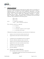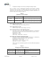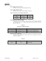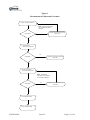
1
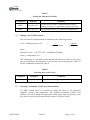
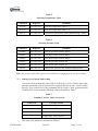
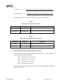
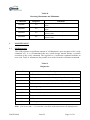
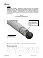
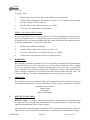
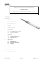
OPERATING & INSTALLATION INSTRUCTIONS
SERIES 9500
PLEASE READ CAREFULLY BEFORE INSTALLING
PART NUMBER:
560550-0096
ISSUE: B
CONTENTS
1.
INTRODUCTION
2.
SAFETY INSTRUCTIONS
3.
HAZARDOUS PRODUCTS
4.
GENERAL
5.
ACTION ON RECEIPT
6.
INSTALLATION
6.1
6.2
7.
OPERATION
7.1
7.2
8.
Lowering the Pressure Probe
Electrical Installation
Analogue Output Probes
SDI12 Operation
MAINTENANCE
8.1
8.2
8.3
Self Diagnostics
Calibration Adjustment
Cleaning
9.
ADVANCED OPERATION
10.
WARRANTY
11.
SERVICING
12.
RETURN TO FACTORY
560550-0096
Issue B
Page 1 of 16
1.
INTRODUCTION
Series 9500 are level measuring transducers used for precise measurements of ground and
surface water levels. The transducers measure pressure and temperature signals and, by
compensating these measured values for temperature effects, the relative density of water
and the specific gravity in the users location , provide a highly accurate and repeatable
‘true’ level measurement. The resultant level is available either as an analogue output or
as a digital output.
2.
SAFETY INSTRUCTIONS
IMPORTANT NOTE: All Gems Pressure and Level & Flow Products are designed and
manufactured in accordance with Sound Engineering Practice as defined by the Pressure
Equipment Directive 97/23/EC. Pressure transducer products designed to meet the highest
risk category ”IV” of the Pressure Equipment Directive are clearly marked on the label by
“CE0086”. Compliance is achieved through modules “B+D”. No other products should
be used as “Safety Accessories” as defined by the PED, Article 1, Paragraph 2.1.3.
EMC : Series 9500 conform with the essential protection requirements of the EMC
Directive 2004/108/EC amended by certified type testing to EN 61326-1 and
EN 61326-2-3. Conformity with the requirements of the CE mark only applies when the
installation conditions described in these instructions have been met.
3.
HAZARDOUS PRODUCTS
The 9500 series may be classified as Electrical, Electro-Mechanical and Electronic
equipment.
These products are tested and supplied in accordance with our published specifications or
individual special requirements that are agreed in writing at time of order. They are
constructed so as not to affect adversely the safety of persons and property when properly
installed, maintained and used by qualified personnel, in the applications for which they
were designed and manufactured. Refer to installation and maintenance instructions for
further details.
4.
GENERAL
*
Transducer should not be subjected to greater than the maximum allowable
pressure range as defined on the transducer label.
*
Transducer should not be subjected to mechanical impact.
*
The effects of decomposition of unstable fluids should be considered by the user
when placing this device in service.
*
Pressure range must be compatible with the maximum level being measured.
560550-0096
Issue B
Page 2 of 16
*
Pressure media must be compatible with the transducer wetted parts which are:UNS31803 Stainless Steel, BS EN 10088-3:1995 No.1.4462.
Polyurethane
Acetal
Nitrile
*
Exposed end of cable must be kept free from moisture.
*
Liquid must not be allowed to freeze in the pressure port.
Full specifications for all products available on request from our Service Department.
5.
ACTION ON RECEIPT
*
Check accessories supplied include:
Calibration Certificate
*
6.
Check details on Calibration Certificate agree with data etched on transducer
body.
INSTALLATION
The 9500 can be put to use in various applications, for example in tubes or boreholes
wider than one inch in diameter, in wells, open waters and in non permanently watercarrying riverbeds. The optional sink weight prevents the probe body from floating to the
surface. The pressure probe can be easily fixated in flowing waters or waters with waves.
When designing the measurement location, observe the hydrodynamic influence of strong
currents (>0.5–1 m/s). Depending on the version and the type of mounting of the
individual components, under pressure or over pressure may occur which may distort the
measuring result.
IMPORTANT: It is not recommended to install the pressure probe in the vicinity of
docks, industrial waste water discharges or areas with high chemical pollution. The
pressure probe is made of high-quality stainless steel and synthetic material. Nevertheless
damaging corrosion may occur, depending on the installation location. For further
information refer to the technical data of he wetted part materials.
6.1
Lowering the Pressure Probe
6.1.1
First determine the minimum and maximum water levels at the measuring point
for example with a stuff gauge or contact gauge. Determine the probe position
from these two values. The following prerequisites must be met:
• Position the probe below the minimal water level
• Difference between maximum water level and probe position < measuring
range of the probe.
560550-0096
Issue B
Page 3 of 16
6.2
6.1.2
Lower the pressure probe at the probe cable to the determined depth.
6.1.3
The cable should be suspended via a suitable cable suspension accessory. The
integral Kevlar core provides mechanical strength within the cable, sufficient to
suspend the probe.
6.1.4
Fine adjustment of the probe position may be performed via the probes digital
interface. If the measured value is to be referenced to a zero level, this can be
achieved by adding a user offset. Therefore, in most cases a coarse positioning of
the probe is sufficient. In non permanently water-carrying riverbeds the pressure
probe delivers a zero reading in a dry condition.
Electrical Installation
The 9500 requires a D.C. power supply between 8V and 30V. The 9500 includes
suppression devices providing surge protection. In the event of a surge these devices can
clamp across the power supply, providing protection against the surge. To avoid damage
to the protection devices the power supply must be current limited so that the maximum
normal operating current is 100mA. Where batteries are used directly this can easily be
achieved via a series resistor, of suitable nominal value and power rating. For mA output
units the second consideration is the total resistance in the current loop. The maximum
loop resistance is calculated by the formula:
Maximum Loop Resistance = (Vs – 8) * 50 ohms
Table 1 states the minimum and maximum resistance recommended.
Table 1
Recommended Power Supply Current Limit
Power Supply
Voltage
12
24
30
Current
Limit
0.1A
0.1A
0.1A
Series Resistance
Note 1
120 ohm
240 ohm
300 ohm
Maximum Loop
Resistance
200 ohm
800 ohm
1100 ohm
Note 1 : Minimum series resistance only required where current limit of 0.1A is not
provided by power supply.
The cable comprises 4 colour-coded cores, with a central vent tube, enclosed by an
aluminium/polyester screen where the screen is in intimate contact with a separate drain
wire. The outer sheath can be of various material, depending upon application and
operating temperature, standard suitable for most water environments is Polyurethane
(immersed operating temperature -20°C to +50°C). Other cables are available on request
for operation at higher temperatures or in more corrosive media. The cable should be
terminated in a dry environment to avoid moisture entering the vent tube. If water enters
this tube then erroneous measurements may result. In humid environments then it is
recommended to terminate the cable into a suitable dessicator. The following electrical
connections should be made:
560550-0096
Issue B
Page 4 of 16
Table 2
Connections for mA Output Probes
Wire Colour
Signal Name
Description
Red
VEx_+ve
Blue
Vex_-ve
None / Screen
Ground
Metalwork of Probe
Green *
SDI12
SDI12 Data
Positive Excitation for the
probe.
Negative Excitation for the
probe.
* Not required for 4 to 20mA output operation
It is recommended to firmly secure the Kevlar core of the cable, for example by knotting
and securing under a fixing screw.
7.
OPERATION
Having installed the transducers as instructed they are ready for use. Before applying
power, check that the correct polarity and excitation levels are being applied. See
Electrical Installation (6.2).
7.1
Analogue Output Probes
Analogue output devices will simply provide a 4mA output for 0 level and a 20mA output
for the full scale level indicated on the product marking. The analogue output can be
adjusted via the digital SDI12 interface with a suitable accessory to include site offsets or
provide full scale, 20mA, output at a different level.
7.2
SDI12 Operation
The SDI12 interface conforms with the SDI12 V1.3 specification. Refer to the SDI12 host
web-site for a full specification, http://www.sdi-12.org/.
In addition to the standard SDI12 command set the 9500 supports a number of extended
commands, providing increased levels of functionality. All sample commands provided
are shown with address a, to use the command substitute the actual address of the unit.
The default address when manufactured is 0.
7.2.1
Setting Up the Measured Variable
The transducer can provide either an output proportional to the applied pressure or
a true level compensated for relative density of water. The preferred measured
value must be set by the XP command as detailed in Table 3.
560550-0096
Issue B
Page 5 of 16
Table 3
Setting the Measured Variable
Command
Response
aXP0!
a0<CR><LF>
Set true level measure, compensated for relative
density of water over temperature and local gravity.
aXP1!
a1<CR><LF>
Set pressure measure, no additional compensation.
7.2.2
Comment
Making a Level Measurement
The corrected level measurement is calculated in the following manner.
Level = mH2O pressure at 4°C
*
1
*
density of water
9.80665
local gravity
where :
Density of water = -6.017777e-6t2 + 0.0000408t+0.999841
where t = temperature in °C.
The temperature is a measured value and thus the density of water at any given
time is calculated by the transducer. The user may enter a local gravity value via
the XE command as detailed in Table 4.
Table 4
Entering the Local Gravity
Command
Response
Comment
aXE9.81!
a9.81<CR><LF>
Sets the local gravity value to 9.81m/s2.
7.2.3
Selecting a Commonly Used Unit of Measurement
For SDI12 output units it is possible to change the units of the measured
variables, pressure and temperature. The extended commands aXUTn! and
aXUPn! are used to change the temperature and pressure units respectively. Note
the value of n specifies the required unit as shown in Tables 5 and 6.
560550-0096
Issue B
Page 6 of 16
Table 5
Selecting Temperature Units
Command
Response
Comment
aXUT0!
a0<CR><LF>
Sets the temperature units to °C
aXUT1!
a1<CR><LF>
Sets the temperature units to °F
aXUT!
a1<CR><LF>
Queries the temperature unit without setting a value
Table 6
Selecting Pressure Units
Command
Response
Comment
aXUP0!
a0<CR><LF>
Sets the pressure units to mH2O
aXUP1!
a1<CR><LF>
Sets the pressure units to ftH2O
aXUP2!
a2<CR><LF>
Sets the pressure units to inH2O
aXUP3!
a3<CR><LF>
Sets the pressure units to bar
aXUP4!
a4<CR><LF>
Sets the pressure units to psi
aXUP!
a4<CR><LF>
Queries the pressure unit without setting a value
Note: the pressure units (bar, psi) are not valid when configured for a true level output.
7.2.4
Setting Up a Custom Unit Scaling
Unit conversion performed by the 9500 is of the form y=mx+c. Where units other
than the commonly used set provided are required then the m and c can be written
directly. This is achieved via the command aXUn,<value>!. Note n represents the
variable to be written with the following value as detailed in Table 7.
Table 7
Variables Used for Unit Conversions
Value of n
Variable written
0
Pressure Units Slope = m
1
Pressure Units Offset = c
2
Temperature Units Slope = m
3
Temperature Units Offset = c
The value of m should be calculated as follows:
560550-0096
Issue B
Page 7 of 16
For Pressure:
m = (Full Scale in User Units – Zero Scale in User Units)
(Full Scale in mH2O at 4°C – Zero Scale in mH2O at 4°C)
For Temperature:
m = (Full Scale in User Units – Zero Scale in User Units)
(Full Scale in °C – Zero Scale in °C)
The appropriate values can then be written as shown in Tables 8 and 9.
Table 8
Setting the Pressure Units to mbar
Command
Response
aXU0,98.0665!
a0<CR><LF>
aXU1,0!
a1<CR><LF>
Comment
Sets the slope m to 98.0665, equivalent to
mbar.
Sets the offset to 0 as 0 mbar = 0 mH2O at
4°C
Table 9
Setting the Temperature Units to Kelvin
Command
Response
aXU2,1!
a1<CR><LF>
Sets the slope m as same as °C.
aXU3,-273!
a1<CR><LF>
Sets the offset to -273 to read in Kelvin.
7.2.5
Comment
Obtaining Maximum and Minimum Measurements
The 9500 supports the following additional measurements via the measure and
concurrent measurement commands.
aM1! = Maximum Level / Pressure
aM2! = Minimum Level / Pressure
aM3! = Maximum Temperature
aM4! = Minimum Temperature
The maximum and minimum values should be reset using the XMM command as
shown in Table 10.
560550-0096
Issue B
Page 8 of 16
Table 10
Resetting Maximums and Minimums
Command
Response
aXMM1!
a1!
aXMM2!
a2!
aXMM3!
a3!
aXMM4!
a4!
8.
MAINTENANCE
8.1
Self Diagnostics
Comment
Resets the maximum level to the current
value.
Resets the minimum level to the current
value.
Resets the maximum temperature to the
current value.
Resets the minimum temperature to the
current value.
The 9500 performs a significant amount of self-diagnostics upon reception of the verify
command, aV!. It is recommended that any system design should include a periodic
execution of the verify command. The response to a verification command includes an
error code. Table 11 summarises the possible error codes from the verification command .
Table 11
Diagnostics
Error Code
Description
0
No Error unit is functioning normally
1
The temperature measurement is beyond the calibrated range
2
The pressure measurement is beyond the calibrated range
4
The non-volatile memory has been incorrectly accessed
8
An analogue signal error exists
16
Reserved
32
The non-volatile user data is in error
64
The non-volatile calibration data is in error
128
RAM error
256
Watchdog error
Note: if an error code > 3 is returned, record the value and contact the manufacturer.
560550-0096
Issue B
Page 9 of 16
8.2
Calibration Adjustment
The 9500 is designed to provide excellent long term stability, however occasionally it is
necessary to verify the calibration and perform adjustment. Gems offer an annual recalibration service, via return to the service department. Alternatively a two point
calibration adjustment of each variable provided by the 9500 is possible via the SDI12
interface. This is achieved through three independent adjustments i.e. pressure,
temperature and mA output. The recommended calibration procedure is detailed in
Figure 1. Writing of calibration adjustment values is performed via the aXZ and aXG
commands. These commands have the following syntax:
aXZn,<value>
aXGn,<value>
where:
n = channel to be calibrated
<value> = value of calibration coefficient.
Three calibration channels are supported:
n = 0 = Pressure
n = 1 = Temperature
n = 2 = mA Output (response to pressure signal)
n = 3 = mA Output (fixed output)
Calibration of any channel is basically the same and consists of 9 simple steps:
1.
Apply zero scale value and record the measured value.
2.
Apply full scale value and record the measured value.
3.
Calculate the errors and adjustment values (if required).
4.
Write the calibration adjustment values to the 9500.
5.
Apply zero scale value and record the measured value.
6.
Apply full scale value and record the measured value.
7.
Calculate new errors and record results.
8.
Write the last and next calibration dates.
9.
Save the calibration.
8.2.1
Example of mA Output Calibration
The mA Output consists of two discrete components:
1.
560550-0096
The analogue to digital conversion of the measured pressure and
temperature values
Issue B
Page 10 of 16
2.
The digital to analogue conversion, providing the analogue output.
Step 1 in Figure 1 refers to checking the calibration of the digital to analogue
conversion of the mA output. For SDI12 output, this step is not necessary. The
calibration of mA output stage can be verified using an extended command to set a
fixed mA output value as shown in Table 12.
Table 12
Calibration of the mA Output
Command
Response
Comment
aXM4
a4.00000<CR><LF>
Sets the mA output to 4mA.
Measure the current and record the actual value
aXM20
a20.0000<CR><LF>
Sets the mA output to 20.0mA
Measure the current and record the actual value
Step 1: Apply Zero Scale Value
Set Point Value 4mA, actual reading 4.005 mA.
Step 2:Apply Full Scale Value
Set Point Value 20mA, actual reading 19.995 mA.
Step 3: Calculate the Errors and Adjustment Values
The value to write to the offset calibration adjustment is calculated by
subtracting the measured value at 4mA from the 4mA set point as shown:
Set point zero = 4.000
Measured zero = 4.005
Offset Value = 4.000-4.005 = -0.005 mA
Step 4: Write the Calibration Adjustment Values
The value to write to the gain calibration adjustment is calculated by
dividing the set point span by the measure span as shown:
Set point span = (20-4) = 16 mA
Measured span = (19.995-4.005) = 15.99mA
Gain value = 16/15.99 = 1.0006254
Table 13 shows the commands required to write the calibration adjustment
to the 9500:
Table 13
Writing the mA Output Calibration
Command
Response
AXZ3,-0.005!
a-0.00500<CR><LF>
AXG3,1.0006254!
A1.006254<CR><LF>
560550-0096
Issue B
Comment
Writes the offset of -5μA to the mA
output zero.
Writes the gain value t the mA output.
Page 11 of 16
Step 5: Apply Zero Scale Value
Set Point Value 4mA, actual reading 4.001 mA.
Step 6:Apply Full Scale Value
Set Point Value 20mA, actual reading 19.999 mA.
Step 7: Calculate Errors and Record Results
Applied
Measured
Error
4.000
4.001
0.001
20.000
19.999
-0.001
Step 8:Write the Calibration Dates
Calibration Dates are stored as a nine character ASCII string. Assuming
the calibration date was 3rd March 2004, then the dates could be written as
shown in Table 14.
Table 14
Writing the Calibration Dates
Command
Response
Comment
aXL,03MAR2004!
a03MAR2004<CR><LF> Writes the last calibration date.
aXN,03MAR2005!
a03MAR2005<CR><LF> Writes the next calibration date.
Step 9: Save the Calibration
All data written remains non-volatile until the save command is executed
as shown in Table 15.
Table 15
Command
Response
AXS0!
a0!
560550-0096
Issue B
Comment
Saves all data
Page 12 of 16
Figure 1
Recommended Calibration Procedure
1. Check mA Output Calibration
Note: mA output calibration
not necessary for SDI12
operation
Acceptable?
Calculate and set required gain and
slope value
N
Y
2. Check Pressure
Measurement Calibration
N
Calculate and set required gain and
slope value
Acceptable?
Y
3. Check Temperature
Measurement Calibration
Note: Temperature
calibration not necessary
for mA output operation
N
Acceptable?
Calculate and set required gain and
slope value
Y
4. Set Calibration Dates
5. Save Calibration Data
560550-0096
Issue B
Page 13 of 16
8.3
Cleaning
Inspection and cleaning of the product is recommended as part of a preventative
maintenance procedure. The required inspection period will depend on the nature of the
application environment. To inspect the product unscrew the nose cover, Figure 2, and
view the sensor diaphragm. The housing should be free from deposits. Cleaning with a
cotton bud is possible, but extreme care must be taken not to deform the sensor diaphragm
during cleaning.
Figure 2
Inspecting and Cleaning the Sensor
9.
ADVANCED OPERATION
CAUTION – Pressure
sensitive diaphragm. Do
not use sharp object to
clean or apply excessive
force.
Nose cover –
unscrew to clean
The 9500 series allows for a number of advanced operations not normally available.
Re-range 4 to 20mA Output
Often users wish to measure a specific water level that is not the same as the full range
output of the transducer. For example, if the sensor output was 10mH2O and the user
wishes to measure up to 4mH2O then without a down range feature the output for the
10mH2O unit in the users applications would be 0 to 40% of the range or 4 to 10.4mA. In
this situation it is possible to use the SDI12 interface to program calibration coefficients
into the sensor to provide 4 to 20mA for the 0 to 4mH2O application, with the 10mH2O
sensor.
560550-0096
Issue B
Page 14 of 16
To re-range a 9500 sensor proceed as follows:
1.
Determine the 9500 sensor full scale and the user application full scale.
2.
Find the required calibration gain. Divide the 9500 sensor full scale by the
user application full scale (e.g. 10/4)
3.
Program the calibration gain into the sensor (via SDI12 interface),
(e.g. aXG2,2.5!).
4.
Check the residual error with zero pressure applied. Note as the gain is increased
any offset errors can be magnified. So for example instead of 4mA expected
sensors reads. 3.959mA.
5.
Program offset in calibration of sensor to remove offset errors (e.g. aXZ2,0.041!)
6.
Save new calibration to non-volatile memory (e.g. aXS0!)
7.
Verify sensor now measures 4 to 20mA for required application range.
Configuring a Reverse Output 20mA to 4mA
If your application demands a 20mA output with zero applied pressure and 4mA output
for full scale applied pressure then the sensor output can be reversed by sending the
following SDI12 commands:
1.
Set calibration gain of mA otuput to -1 (e.g. aXG2,-1!)
2.
Set calibration offset of mA output to +24 (e.g. aXZ2,24!)
3.
Save new calibration to non-volatile memory (e.g. aXS0!)
4.
Verify sensor now measures 20mA to 4mA for 0 to full scale applied pressure
Applying a Filter to the mA Output
In applications that are inherently difficult to measure, for example waves on reservoir,
then the 9500 series can be configured to apply a mean or median filter via the SDI12
interface before updating the analogue mA output. The filter command is described
below:
SDI12 Command:
Neptune Response:
0XFt,nn,xxxx!
0t,nn,xxxx<CR><LF>
Where:
T = type of filter
0 = MEAN,
1 = MEDIAN
nn = number of values to filter, maximum 12
xxxx = 220mS intervals between measurements, maximum period 1 hour
560550-0096
Issue B
Page 15 of 16
To apply a filter:
1.
Determine the type of filter and period suitable for the application.
2.
Send the filter command to the 9500 series sensor (e.g. 12 reading mean, sampling
period 15 minutes, aXFt,12,4091A)
3.
Save the filter to non-volatile memory (e.g. aXS0!)
4.
Verify the filter performance in application.
Adding a Site Offset to SDI12 Output
In some applications it is necessary to measure a site value including some reference data
point, for example sea level. Assuming the sensor is installed 10m above sea level then it
is possible to have all reported readings add 10m, thus acquiring the data without the need
for further modification. To add a site offset then:
10.
1.
Determine the offset to be applied.
2.
Add the offset to the pressure units (e.g. aXU1,10!)
3.
Save new calibration to non-voltaile memory (e.g. aXS0!)
4.
Verify sensor now measures 10m for 0 applied pressure
WARRANTY
The Company warrants its products to be free from defects in material and workmanship
in normal use and service for a period of one year from date of shipment. The Company
reserves the right and option to refund the purchase price in lieu of repair or replacement
upon evaluation of the returned original part. Modification, misuse, attempted repair by
others, improper installation or operation shall render this guarantee null and void. The
Company makes no warranty of merchantability or fitness for a part or purpose.
11.
SERVICING
The transducer cannot be repaired locally and if damaged should be returned to ourselves
at the address shown below or to accredited dealers when a replacement/repair is required:
Gems Sensors & Controls
Lennox Road
Basingstoke
Hants. RG22 4AW
12.
RETURN TO FACTORY
PLEASE NOTE: To comply with Health and Safety requirements, the instrument must
be clean and safe to handle and accompanied by a formal statement to that effect duly
signed by an authorised officer of the Company.
Any instrument returned without certification will be quarantined and no action will occur
until cleared. It may ultimately be returned to you and subject to a transportation charge.
560550-0096
Issue B
Page 16 of 16