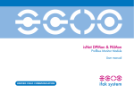
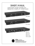
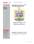
1
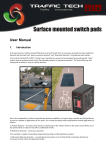
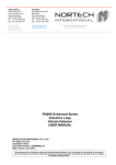
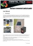
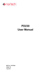
Nortech Detection Pty Ltd
Unit1, Bldg 5, Forest Central Business Park,
49 Frenchs Forest Road,
Frenchs Forest NSW 2086
PO Box 6011, Frenchs Forest DC, NSW 2086
Tel: 02 8977 4047 Fax: 02 9475 4742
email: [email protected]
web: www.nortechdetection.com.au
Short form User Manual
PD132 / PD134 Enhanced Vehicle Detector
The PD130 is a single channel microprocessor based detector designed specifically for parking and vehicle access
control application. The PD130 has been designed using the most up-to-date technology in order to meet the
requirements of a vast number of parking applications in terms of operating conditions and options available to the user.
The primary function of the detector is to detect vehicle presence by means of an inductance change caused by the
vehicle passing over a wire loop buried under the road surface.
The detector has been designed for ease of installation and convenience. The various modes are selected by changing
the positions of the switch on the front of the unit.
The switches allow for different loop frequency settings, sensitivity settings and mode settings.
The PD130 provides visual output (LED) on the front of the enclosure and relay changeover contacts are taken on the
11-pin connector at the rear of the enclosure. The LED indicates the power has been applied to the unit, that a vehicle is
present over the loop and if there is a fault on the loop. The Presence relay is fail-safe and will close on a vehicle detect
or in the event of power failure.
In accordance with the manufacturer’s policy of updating and improving product designs, product specification is
subject to change without notice. While every care has been taken with the preparation of this document, no warranty
is offered to the completeness or accuracy of this information.
PD132 / PD134 Enhanced Vehicle Detector - User Instructions
Page 2 of 9
1.
Operating Instructions
1.1.
Switch Setting Selections
1.1.1. Frequency Switch
The frequency switches are the lower two switches, numbered 1 and 2. There are four frequency selections and are set
out as follows:
SW2
Off
SW1
Off
- High
On
Off
- Medium-High
Off
On
- Medium-Low
On
On
- Low
The frequency switches allow the loop to be shifted higher or lower depending on the switch position. The frequency of
the loop is determined by the loop size, and the frequency of the switch simply causes a frequency shift on the loop.
Where more than one detector is used the detectors must be set-up to ensure that there is no cross-talk (interference)
between the detectors. This can be achieved by ensuring that the loops of the two detectors are spaced sufficiently apart
(approximately 2 metres between adjacent edges) and also ensuring that the detectors are set to different frequencies.
As a general rule, the detector connected to the inductive loop with the greatest inductance should be set to operate at
the lowest frequency. Loop inductance increases as loop size, number of turns in the loop and feeder length increases.
1.1.2. Sensitivity
The sensitivity of the detector allows the detector to be selective as to the change of inductance necessary to produce an
output. There are four sensitivity selections and these are set as follows: SW4
Off
SW3
Off
- High
On
Off
- Medium-High
Off
On
- Medium-Low
On
On
- Low
PD132 / PD134 Enhanced Vehicle Detector - User Instructions
Page 3 of 9
1.1.3. Automatic Sensitivity Boost
Automatic sensitivity boost is a mode that alters the “undetect” level of the detector. This mode is selected by switch
No. 5 on the front of the enclosure and is as follows: SW5
Off
On
- Disabled
- Enabled
Automatic sensitivity boost causes the sensitivity to be boosted to a maximum on
detection of a vehicle, and
maintained at this level during the presence of the entire vehicle over the loop. When the vehicle departs the loop and
the detection is lost the sensitivity reverts to the pre-selected level.
1.1.4. Filter Mode
The filter mode is selected with the mode switch No. 6. The filter produces a delay turn-on time of two seconds when a
vehicle is occupies the loop. This is to enable small, unwanted objects to pass over the loop without being detected.
The filter option may be used on any sensitivity setting and is selected as follows: SW6
Off
On
- Disabled
- Enabled
1.1.5. Pulse Relay
The pulse relay may be made to operate on detect (entry) or on “undetect” (exit) of a vehicle. This option is selected
from Switch No. 7 and is configured as follows: SW7
Off
On
- Pulse on Detect
- Pulse on Undetect
1.1.6. Presence Time
The presence time may be set to permanent presence or to limited presence. In permanent presence mode the detector
will continuously compensate for all environmental changes whilst there is a vehicle present over the loop. The
presence mode is set with switch No. 8 and is configured as follows: SW8
Off
On
- Limited Presence
- Permanent Presence
1.1.7. Reset Switch
The detector automatically tunes to the inductive loop connected to it when the power is applied, whether on initial
installation or after any break in power supply. Should it be necessary to re-tune the detector, as may be required after
changing any of the switches or after moving the detector from one installation to another, momentary operation of the
RESET switch will initiate the automatic tuning cycle.
PD132 / PD134 Enhanced Vehicle Detector - User Instructions
Page 4 of 9
1.2.
Front Panel Indicator
While the detector is tuning, the ON (Red) LED will glow and the OUTPUT LED (Green) will extinguish when the
system is tuned. Thereafter, the green LED will flash at a rate of 1 Hz. This is used to indicate the frequency of the loop
to the user. Every flash of the LED is equivalent to 10 kHz. It will stop when the operating frequency is reached. This
operation is also performed whenever the reset button is depressed.
The ON (red) LED will glow permanently to indicate that the unit is functional. The red LED also serves as an optical
interface to the DU100 Diagnostic Unit.
If faults exist with the loop the green LED will come on and flash off at the rate of 2Hz indicating the fault. If the fault
is self-healing the detector will continue to operate but the LED will remain on indicating to the user that a fault has
occurred. The LED will go off for a moment during an “undetect”, indicating this state, thereafter returning on. This
condition can be restored by removing the power or by depressing the reset button.
The green LED will also glow whenever a vehicle is detected passing over the inductive loop.
1.3.
Detector Tuning
Tuning of the detector is fully automatic. When power is applied to the detector upon installation of the system, or
when a reset is initiated, the detector will automatically tune itself to the loop to which it is connected. The detector
will tune to any loop to inductance range 20 to 1500 microhenries.
This wide range ensures that all loop sizes and feeder combinations will be accommodated in the tuning range of the
detector.
Once tuned, any slow environmental change in loop inductance is fed to a compensating circuit within the detector that
keeps the detector correctly tuned.
1.4.
Detector Sensitivity
Sensitivity of the detection system is dependent on factors such as loop size, number of turns in the loop, feeder length
and the presence of metal reinforcing beneath the loop.
The nature of the application determines the required sensitivity that may be adjusted by means of the sensitivity
switches on the front of the enclosure.
Sensitivity levels of the PD130 have been carefully optimised for parking and vehicle access control applications. The
detection of small unwanted objects such as bicycles and trolleys can be eliminated by selecting lower sensitivity levels
whilst high-bed vehicles and vehicle/trailer combinations will not loose detection by using automatic sensitivity boost
(ASB) option.
ASB operates as follows. When ASB is disabled the undetect level is dependent on the sensitivity setting of the
detector. Hence as the detector is made less sensitive, the undetect level will reduce accordingly. When the ASB is
enabled the undetect level will always be the same irrespective of the sensitivity setting and will be equivalent to the
undetect level when the sensitivity is on maximum setting.
2.
Modes of Operation
In the presence mode the detector will give a continuous output during the presence of a vehicle over the inductive loop.
As the detector is designed with the permanent presence feature, the detector will indicate vehicle presence for an
unlimited period of time. If the permanent presence is not selected, then the detect time will be dependent on the
change of inductance. The presence time on the limited presence setting will be approximately 1 hour for 3% ∆ L/L
PD132 / PD134 Enhanced Vehicle Detector - User Instructions
Page 5 of 9
The pulse relay outputs a pulse of 150 milliseconds duration. When set to “pulse on detect” the detector will give a
pulse on detection of a vehicle and when set to “pulse on undetect” the detector will give a pulse output when the
vehicle leaves the loop.
The presence output is known as a fail-safe output. This implies that in the event of a power failure the detector will
give a detect output. The pulse outputs are not fail safe and will not operate if a failure occurs.
3.
Technical Specification
Self-tuning range
20 to 1500µH
Sensitivity
Four step switch selectable:
High 0.02% Δ L/L
Medium High 0.05% Δ L/L
Medium Low 0.10% Δ L/L
Low 0.50% Δ L/L
Filter
Switch selectable 2 Second filter
Presence Relay
Fail-safe
Pulse Relay
Switch selectable: Pulse on detect
Pulse on undetect
Pulse Output Duration
150 milliseconds
Response Times
100 milliseconds
Drift Compensation Rate
Approx. 1% Δ L/L per minute
Relay Rating
5A @ 230VAC
Surge protection
Loop isolation transformer, gas discharge tubes,
and Zener diode clamping on loop input
Power requirements
12 - 24V AC/DC (PD134)
230V AC ±10 % ( 48 to 62Hz )
Requirement: 1.5 VA Maximum @ 230V
Operating Temperature
-40°C to +70°C
Mounting Position
Shelf or DIN rail mounting
Connections
11-pin submagnal type (JEDEC No. B11-88)
Size of Housing
78mm (H) X 41mm (W) X 80mm (D)
PD132 / PD134 Enhanced Vehicle Detector - User Instructions
Page 6 of 9
4.
Wiring Connections
11-pin connector wiring
pin
1
2
3
4
5
6
7
8
9
10
11
5.
colour
designation
Red
Black
Grey
Violet
Yellow
Brown
Blue
Blue
Green
Pink
White
Live
Neutral
Pulse Relay
Pulse Relay
Presence Relay
Presence Relay
Loop
Loop
Earth
Presence Relay
Pulse Relay
230V AC 50/60 Hz
OR 12 - 24V AC/DC
Normally Open contact
Common contact
Normally Open contact
Common contact
Twist this
pair
Normally Closed contact
Normally Closed contact
Part Numbers
Part Number
301FT0101_01
Model Number
PD132 - Enhanced
Description
230 V ac operation
301FT0122_01
PD134 - Standard
12 - 24V ac/dc operation
895FT 0001
DU100 - English
Hand Held Diagnostic Unit
301FT0041
Option - 1 metre plug and harness
CTR119090
DIN Rail Screw terminal base
PD132 / PD134 Enhanced Vehicle Detector - User Instructions
Page 7 of 9
6.
Installation Guide
Optimum functioning of the detector module is largely dependent on factors associated with the inductive sensor loop
connected to it. These factors include choice of material, loop configuration and correct installation practice. A
successful inductive loop vehicle detection system can be achieved bearing the following constraints in mind, and
strictly following the installation instructions. The detector must be installed in a convenient weatherproof location as
close as possible to the loop.
6.1.
Operational Constraints
6.1.1. Crosstalk
When two loop configurations are in close proximity, the magnetic fields of one can overlap and disturb the field of the
other. This phenomenon, known as crosstalk, can cause false detects and detector lock-up.
Crosstalk between adjacent loops operating from different detector modules can be eliminated by:
1.
Careful choice of operating frequency. The closer together the two loops, the further apart the frequencies of
operation must be.
2.
Separation between adjacent loops. Where possible a minimum spacing of 2 metres between loops should be
adhered to.
3.
Careful screening of feeder cables if they are routed together with other electric cables. The screen must be
earthed at the detector end only.
6.1.2. Reinforcing
The existence of reinforced steel below the road surface has the effect of reducing the inductance, and therefore the
sensitivity, of the loop detection system. Hence, where reinforcing exists 2 turns should be added to the normal loop, as
referred to in section 5.3.
The ideal minimum spacing between the loop and the cable and steel reinforcing is 150mm, although this is not always
practically possible. The slot depth should be kept as shallow as possible, taking care that the feeder remains exposed
after the sealing compound has been applied.
WARNING : Cutting into post tensioned concrete slabs can have catastrophic consequences. As a general rule
30mm is the deepest slot depth allowable in such cases. When any doubt exists the structural engineer’s
approval must be sought prior to commencement.
6.2.
Loop and Feeder Specification
The loop and feeder should preferably constitute a single unjoined length of insulated copper conductor, with a
minimum rating 15Amp.
Joints in the loop or feeder are not recommended. Where this is not possible, joints are to be soldered and terminated in
a waterproof junction box. This is extremely important for reliable detector performance.
6.3.
Sensing Loop Geometry
Sensing loops should, unless site conditions prohibit, be rectangular in shape and should normally be installed with the
longest sides at right angle to the direction of traffic movement. These sides should ideally be 1 metre apart.
PD132 / PD134 Enhanced Vehicle Detector - User Instructions
Page 8 of 9
The length of the loop will be determined by the width of the roadway to be monitored. The loop should reach to
within 300mm of each edge of the roadway.
In general, loops having a circumference measurement in excess of 10 metres should be installed using two turns of
wire, while loops of less than 10 metres in circumference, should have three turns or more. Loops having a
circumference measurement less than 6 metre should have four turns. It is good practice at time of installation to
construct adjacent loops with alternate three and four turn windings.
7.
Loop Installation
All permanent loop installations should be installed in the roadway by cutting slots with a masonry cutting disc or
similar devise. A 45° crosscut should be made across the loop corners to reduce the chance of damage that can be
caused to the loop at right angle corners.
NOMINAL SLOT WIDTH: 45mm
NOMINAL SLOT DEPTH : 30mm TO 50mm
A slot must also be cut from the loop circumference at one corner of the loop to the roadway edge to accommodate the
feeder.
A continuous loop and feeder is obtained by leaving a tail long enough o reach the detector before inserting the cable
into the loop slot. Once the required number of turns of wire is wound into the slot around the loop circumference, the
wire is routed again via the feeder slot to the roadway edge. A similar length is allowed to reach the detector and these
two free ends are twisted together to ensure they remain in close proximity to one another (minimum 20 turns per
metre). Maximum recommended feeder length is 100 metres.
It should be noted that the loop sensitivity decreases as the feeder length increases, so ideally the feeder cable should be
kept as short as possible.
The loops are sealed using “quick-set” black epoxy compound or hot bitumen mastic to blend with the roadway surface.
Figure 1
Slot details
PD132 / PD134 Enhanced Vehicle Detector - User Instructions
Page 9 of 9
Figure 2
Adjacent loops connected to different detector modules