1
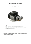
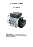
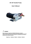
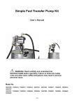
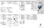
DC 12V/24V Fuel Transfer Pump Kit
User’s Manual
WARNING: Read carefully and understand all
INSTRUCTIONS before operating. Failure to follow the safety
rules and other basic safety precautions may result in serious
personal injury.
Model No. 10304010, 10304011, 10304012, 10304013
1 OF 11
A. INDEX
A………………………………………………………………………………………………………………. Index
B………………………………………………………………………………………..Declaration of Conformity
C……………………………………………………………………………………………...Machine Description
D…………………………………………………………………………………………………….Technical Data
D1…………………………………………………………………………………………………Electrical Data
E……………………………………………………………………………………………...Operating Conditions
E1…………………………………………………………………………………….Environmental Conditions
E2…………………………………………………………………………………….... Electrical Power Supply
E3………………………………………………………………………………………..…………Working Cycle
E4………………………………………………………………………Fluids Permitted / Fluids Not Permitted
F………………………………………………………………………………………………Moving and Transport
G……………………………………………………………………………………………………………Installation
G1……………………………………………………………………….......Disposing Of The Packing Material
G2…………………………………………………………………………………………..Preliminary Inspection
G3…………………………………………………………………………………………..Positioning the Pump
G4…………………………………………………………………………………………Connecting the Tubing
G5……………………………………………………..Considerations Regarding Delivery And Suction Lines
G6……………………………………………………………………………………………………Configurations
G7…………………………………………………………………………………………..Electrical Connections
H………………………………………………………………………………………………………...Initial Start-Up
I……………………………………………………………………………………………………………….Daily Use
J……………………………………………………………………………………………...Problems and Solutions
K…………………………………………………………………………………………………………..Maintenance
L…………………………………………………………………………………………………………….Noise Level
M……………………………………………………………………………...Disposing Of Contaminated Materials
N……………………………………………………………………………………………… Diagram and Parts List
O……………………………………………………………………………………………………..Install Dimensions
2 OF 11
B.
DECLARATION OF CONFORMITY
DECLARATION OF CONFORMITY
IN CONFORMANCE WITH THE DIRECTIVES
98/37/EC (Machinery Directive)
2004/104/EC (EMC Directive)
INTRADIN (SHANGHAI) MACHINERY
118 DUHUI ROAD, MINHANG DISTRICT, SHANGHAI, 201109 CHINA
DECLARES THAT THE FOLLOWING PUMP MODELS:
10304010/10304011/10304012/10304013
To which this declaration refers, conform to the following applicable regulations:
EUROPEAN REGULATIONS:
EN ISO 12100-1: 2003 - Safety of machinery - Basic concepts, general principles for design - Part 1: Basic
terminology, methodology
EN ISO 12100-2: 2003 - Safety of machinery - Basic concepts, general principles for design - Part 2: Technical
principles
EN 60034-1: 2004 - Rotating electrical machines - Part 1: Rating and performance
EN 55014-1: 2006 - Electromagnetic compatibility - Requirements for household appliances, electric tools and
similar apparatus - Part 1: Emission
EN 55014-2: 1997/+A1:2001 - Electromagnetic compatibility - Requirements for household appliances, electric
tools and similar apparatus - Part 2: Immunity product family standard
C.
MACHINE DESCRIPTION
PUMP: self-priming, volumetric, rotating vane pump, equipped with by-pass valve.
MOTOR: Brush motor, DC, low tension with intermittent cycle, closed type in protection class IP55, directly
flanged to the pump body.
D.
TECHNICAL DATA
D1. Electrical Data
PUMP MODEL
FUSES
ELECTRICAL POWER
Current
Voltage(V)
CURRENT
Maximum(*)
(Amp)
10304010
25
DC
12
24
10304011
15
DC
24
13
10304012
25
DC
12
24
10304013
15
DC
24
13
(*) referred to operations in by-pass mode.
E. OPERATING CONDITIONS
E1.
Environmental Conditions
3 OF 11
Temperature: Min. -20℃, Max. +60℃
Relative Humidity: Max. 90%
ATTENTION!
The temperature limits shown apply to the pump components and must be respected to avoid possible
damage or malfunction.
E2. Electrical Power Supply
Depending on the model, the pump must be supplied by a single-phase alternating current line whose
nominal values are shown in the table in Paragraph D1 – ELECTRICAL DATA.
The maximum acceptable variations from the electrical parameters are: Voltage +/-5% of the nominal value.
Power from lines with values outside the indicated limits can damage the electrical components.
ATTENTION!
Power from lines with values outside the indicated limits can damage the electrical components.
E3. Working Cycle
ATTENTION!
Extreme operating conditions with working cycles longer than 30 minutes can cause the motor temperature
to rise, thus damaging the motor itself.
Each 30-minute working cycle should always be followed by a 30-minute power-off cooling phase.
ATTENTION!
Functioning under by-pass conditions is only allowed for brief periods of time (2-3minutes maximum).
E4. Fluids Permitted / Fluids Not Permitted
PERMITTED
DIESEL FUEL at a VISCOSITY from 2 to 5.35 cSt (at a temperature of 37.8℃)
Minimum Flash point (PM): 55℃
NOT PERMITTED
Description
Related Dangers
Gasoline
Fire – Explosion
Inflammable Liquids With Pm<55℃
Fire – Explosion
Liquids With Viscosity>20cst
Motor Overload
Water
Pump Oxidation
Food Liquids
Contamination Of The Same
Corrosive Chemical Products
Pump Corrosion, Injury To Persons
Solvents
Fire – Explosion, Damage To Gasket Seals
F. MOVING AND TRANSPORT
Given the limited weight and size of the pumps (see overall dimensions), moving the pumps does not require
4 OF 11
the use of lifting devices.
The pumps were carefully packed before shipment. Check the packing material on delivery and store in the
dry place.
G. INSTALLATION
G1. Disposing Of the Packing Material
The packing material does not require special precautions, not being in any way dangerous or polluting.
Refer to local regulations for its disposal.
G2. Preliminary Inspection
• Check that the machine has not suffered any damage during transport or storage.
• Clean the inlet and outlet openings, removing any dust or residual packing material.
• Check that the electrical specifications correspond to those shown on the identification plate.
G3. Positioning the Pump
• The pump can be installed in any position (pump axis vertical or horizontal)
• Attach the pump using screws of adequate diameter for the attachment holes provided in the base of the
pump (see the section “OVERALL DIMENSIONS” for their position and dimension).
ATTENTION!
THE MOTORS ARE NOT OF AN ANTI-EXPLOSIVE TYPE.
Do not install them where inflammable vapours can be present.
G4. Connecting the Tubing
• Before connection, make sure that the tubing and the suction tank are free of dirt and thread residue that
could damage the pump and its accessories.
• Before connecting the delivery tube, partially fill the pump body with diesel fuel to facilitate priming.
• Do not use conical threaded joints that could damage the threaded pump openings if excessively tightened.
• The pump is not provided with any filter. Always install suction filter (on all of the models it is included).
SUCTION TUBING:
- Minimum recommended nominal diameter: 3/4”
- Nominal recommended pressure: 10bar/145PSI
- Use tubing suitable for functioning under suction pressure
DELIVERY TUBING:
- Minimum recommended nominal diameter: 3/4”
- Nominal recommended pressure: 10bar/145PSI
ATTENTION!
It is the installer’s responsibility to use tubing with adequate characteristics.
The use of tubing unsuitable for use with diesel fuel can damage pump, injure persons and cause
pollution.
5 OF 11
Loosening of the connections (threaded connections, flanging, gasket seals) can cause serious
ecological and safety problem.
Check all the connections after the initial installation and on a daily basis after that.
Tighten the connections, if necessary.
G5. Considerations Regarding Delivery and Suction Lines
DELIVERY
The choice of pump mode must be made keeping the characteristics of the system in mind.
The combination of the length of the tubing, the diameter of the tubing, the flow rate of the diesel fuel and the
line accessories installed can create back pressure greater than the maximums anticipated such as to cause
the (partial) opening of the pump by-pass with the consequent noticeable reduction of the flow rate supplied.
In such cases, to allow correct functioning of the pump, it is necessary to reduce system resistance, using
shorter tubing and/or of wider diameter and line accessories with less resistance (e.g. an automatic
dispensing nozzle for greater flow rates).
SUCTION
All models are equipped with a self-priming pump with a good suction capacity.
During the start-up phase, with an empty suction tube and the pump wetted with fluid, the electric pump unit
is capable of suctioning the liquid with a maximum difference in height of 2 meters. It is important to point out
that the priming time can be as long as one minute and the pressure of an automatic dispensing nozzle on
the delivery line prevents the evacuation of air from the installation, and, therefore, prevents proper priming.
For this reason, it is always advisable to prime the pump without an automatic delivery nozzle, verifying the
proper wetting of the pump. The installation of a foot valve is recommended to prevent the emptying of the
suction tube and to keep the pump wet. In this way, the pump will subsequently always start up immediately.
When the system is functioning, the pump can work with pressure at the inlet as high as 0.5bar/7PSI, beyond
which cavitation phenomena can begin, with a consequent loss of flow rate and increase of system noise.
As we have said up to this point, it is important to guarantee low suction pressure by using short tubing of a
diameter equal to or larger than recommended, reducing curves to a minimum and using suction filter of wide
cross-section and foot valves with the lowest possible resistance.
The difference in height between the pump and the fluid level must be kept as small as possible and, at any
rate, within the 2 meters anticipated for the priming phase.
If this height is exceeded, it will always be necessary to install a foot valve to allow for the filling of the suction
tube and provide tubing of wider diameter. It is recommended that the pump not be installed at a difference in
height greater than 3 meters.
ATTENTION!
In the case that the suction tank is higher than the pump, it is advisable to install an anti-siphon valve
to prevent accidental diesel fuel leaks.
6 OF 11
Dimension the installation in order to control the back pressure due to water hammering.
G6. CONFIGURATIONS
Electric pump with terminal strip box complete of switch (on 12V and 24V versions), with safety fuse and
pincers for connection to the battery, handle for easier moving, 3/4” anti-static tube for diesel fuel dispensing,
manual nozzle and foot filter to be installed at the beginning of the suction tube.
G7. Electrical Connections
• Terminal strip box complete of:
- ON/OFF switch;
- Safety fuse against short circuits and overcurrent, featuring the following characteristics:
25A for 12V models
15A for 24V models
• 2m/6.6ft power cable complete of pincers for connection to the battery
RED cable: positive pole (+)
BLACK cable: negative pole (-)
ATTENTION!
IT IS THE INSTALLER’S RESPONSIBILITY TO PREFORM THE ELECTRICAL CONNECTIONS WITH
RESPECT FOR THE APPLICABLE REGULATIONS.
Respect the following (not exhaustive) instructions to ensure a proper electrical installation:
• During installation and maintenance, make sure that the electric supply lines are not live.
• Use cables characterized by the minimum cross-sections, nominal voltages and wiring-type adequate to
the electrical characteristics shown in paragraph E2 – ELECTRICAL SPECIFICATIONS and the installation
environment.
• Always close the cover of the strip box before supplying electrical power.
• Check the correct rotation direction of the pump.
If it is inverted, check the polarity of the connection cable.
7 OF 11
H. INITIAL START-UP
• Check that the quantity of diesel fuel in the suction tank is greater than the amount you wish to transfer.
• Make sure that the residual capacity of the delivery tank is greater than the quantity you wish to transfer.
• Do not run the pump dry. This can cause serious damage to its components.
• Make sure that the tubing and line accessories and in good condition.
• Diesel fuel leak can damage objects and injure person.
• Never start or stop the pump by connecting or cutting out the power supply.
• Do not operate switches with wet hands.
• Prolonged contact with diesel fuel can damage the skin. The use of glasses and gloves is recommended.
ATTENTION!
Extreme operating conditions with working cycles longer than 30 minutes can cause the motor
temperature to rise, thus damage the motor itself.
Each 30-minute working cycle should always be followed by a 30-minute power-off cooling phase.
In the priming phase the pump must blow the air initially present in the entire installation out of the delivery
line. Therefore it is necessary to keep the outlet open to permit the evacuation of the air.
ATTENTION!
If an automatic type dispensing nozzle is installed at the end of the delivery line, the evacuation of
the air will be difficult because of the automatic stopping device that keeps the valve closed when the
line pressure is too low. It is recommended that the automatic dispensing nozzle be temporarily
disconnected during the initial start-up phase.
The priming phase can last from several second to a few minutes, as a function of the characteristics of the
system. If this phase is prolonged, stop the pump and verify:
• That the pump is not running completely dry;
• That the suction tubing is not allowing air to seep in;
• That the suction filter is not clogged;
• That the suction height does not exceed 2m. (if the height exceeds 2m, fill the suction hose with fluid);
• That the delivery tube is allowing the evacuation of the air.
When priming has occurred, verify that the pump is operating within the anticipated range, in particular:
• That under conditions of maximum back pressure, the power absorption of the motor stays within the
values shown on the identification plate;
• That the suction pressure is not greater than 0.5bar;
• That the back pressure in the delivery line is not greater than the maximum back pressure foreseen for the
pump.
I. DAILY USE
a. If using flexible tubing, attach the ends of the tubing to the tanks. In the absence of an appropriate slot,
solidly grasp the delivery tube before beginning dispensing.
b. Before starting the pump, make sure that the delivery valve is closed (dispensing nozzle or line valve).
c. Turn the ON/OFF switch on. The by-pass valve allows functioning with delivery closed only for brief
8 OF 11
periods.
d. Open the delivery valve, solidly grasping the end of the tubing.
e. Close the delivery valve to stop dispensing.
f. When dispensing is finished, turn off the pump.
ATTENTION!
Functioning with the delivery closed is only allowed for brief periods (2 / 3 minutes maximum). After use,
make sure the pump is turned off.
J. PROBLEMS AND SOLUTIONS
PROBLEM
The Motor is not turning
The motor turns slowly when
starting
Low or no flow rate
Increased pump noise
Leakage from the pump body
POSSIBLE CAUSE
CORRECTIVE ACTION
Lack of electric power
Check the electrical connecting
Rotor Jammed
Check for possible damage or
obstruction of the rotating
components
Motor Problems
Contact the Service Department
Low voltage in the electric power
line
Bring the voltage back within the
anticipated limits
Low level in the suction tank
Refill the tank
Foot valve blocked
Clean and/or replace the valve
Filter clogged
Clean the filter
Excessive suction pressure
Lower the pump with respect to
the level of the tank or increase
the cross-section of the tubing
High loss of head in the delivery
circuit (working with the by-pass
open)
Use shorter tubing or of greater
diameter
By-pass valve blocked
Dismantle the valve, clean and/or
replace it.
Air entering the pump or the
suction tubing
Check the seals of the
Connections
A narrowing in the suction tubing
Use tubing suitable for working
under suction pressure
Low rotation speed
Check the voltage at the pump.
Adjust the voltage and/or use
cables of greater cross-section
The suction tubing is resting on
the bottom of the tank
Raise the tubing
Cavitation occurring
Reduce suction pressure
Irregular
by-pass
functioning
of
the
Dispense fuel until the air is
purged from the by-pass system
Air present in the diesel fuel
Verify the suction connection
Seal Damaged
Check and replace the seal
9 OF 11
K. MAINTENANCE
All models are designed and constructed to require a minimum of maintenance.
In any case always bear in mind the following basic recommendations for a good functioning of the pump:
- On a weekly basis, check that the tubing joints have not loosened, to avoid any leakage.
- On a monthly basis, check the pump body and keep it clean of any impurities.
- On a weekly basis, check and keep clean the line suction filter.
- On a monthly basis, check that the electric power supply cables are in good condition.
- Check on a monthly basis and keep clean the dispensing nozzle provided with all the models. Anyway
keep clean any other final check valve installed.
- Check on a monthly basis and keep the suction filters clean.
L. NOISE LEVEL
Under normal working conditions the noise emission from all models does not exceed the valve of 70 db at a
distance of 1 meter from the electric pump.
M. DISPOSING OF CONTAMINATED MATERIALS
In the event of maintenance or demolition of the machine, do not disperse contaminated parts into the
environment. Refer to local regulations for their proper disposal.
N. DIADRAM AND PARTS LIST
10 OF 11
Item#
1
2
3
4
5
6
7
8
9
10
11
12
13
14
15
16
17
18
19
20
21
22
23
24
25
26
27
28
29
30
31
32
Description
SCREW M5×10
FRONT COVER
O-RING
ROTOR
BLADE
PUMP BODY
BY PASS SPRING
HOSE HOLDER 3/4” + O-RING
HANDLE
CLAMP 22-32 SCREW
HOLDER 1”
MANUAL NOZZLE
FUSE 15A/25A
FUSE-CARRIER
SINGLE-POLE SWITCH
LINE CORD 2MT
TERMINAL BOARD
SCREW M4×15
COMPACTION NUT
TAPER RING
NUT M5
POWER LINE
MOTOR 12V/24V
BEARING
SPRING COLLAR
SEAL
TUBE
HOLDER 1”
FILTER
BY PASS VALVE
BASE
KEY
O. INSTALL DIMENSIONS
Unit of measurement: mm
11 OF 11
Quantity
8
1
1
1
5
1
1
2
1
4
1
1
1
1
1
1
1
2
1
1
2
2
1
2
1
1
2
1
1
1
1
1