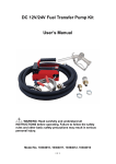
1
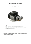
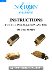
AC Gear-type Oil Pump
User’s Manual
WARNING: Read carefully and understand all
INSTRUCTIONS before operating. Failure to follow the
safety rules and other basic safety precautions may result
in serious personal injury.
Model No. 17320400, 17320401, 17320500, 17320501
1
1. DECLARATION OF CONFORMITY
DECLARATION OF CONFORMITY
IN CONFORMANCE WITH THE DIRECTIVES
98/37/EEC (MACHINERY)
73/23/EEC (PRESSURE VESSELS)
89/336/EEC (ELECTOR-MAGNETIC COMPATIBILITY)
THE MANUFACTURER
INTRADIN (SHANGHAI) MACHINERY
118 DUHUI ROAD, MINHANG DISTRICT, SHANGHAI, 201109 CHINA
DECLARES THAT THE FOLLOWING PUMP MODELS: 17320400, 17320401, 17320500,
17320501 CONFORMS TO THE FOLLOWING EUROPEAN REGULATIONS:
EN292-1-92 – Safety of Machinery – General Concepts, basic principles for design – terminology,
basic methodology
EN292-2-92 – Safety of Machinery – General Concepts, basic principles for design –
specifications and technical principles
EN294-93 – Safety of Machinery – safe distances to prevent the operator’s upper limbs from
reaching dangerous areas
EN60034-1-2000 – Rotating electrical Machinery – nominal and functional specifications
EN60034-5-2001 – Classification of grades of protection for the housings of rotating electrical
machinery
EN61000-6-3 – Electro – magnetic compatibility – generic emission standards
EN61000-6-1 – Electro – magnetic compatibility – generic immunity standards
EN55014-1-00(A1/99-A2/99) –Limits and methods for measuring radio disturbance characteristics
EN55014-2-97 – Electrical motor – operated and thermal appliances for household and similar
purposes, electric tools and similar electrical apparatus
EN60204-1-98 –Safety of machinery – electrical equipment of machines
2. Machine Description
Pump:Electric self-priming rotary internal gear pump, equipped with a by-pass valve
Motor: Asynchronous motor, 4-pole, closed type (Protection class IP55), self-ventilating,
flange-mounted directly to the pump body.
3.Technical Information
2
3.1 Electrical Information
ELECTRICAL POWER
POWER
Pressure
Flow Rate
PUMP MODEL
Current
Voltage
(V)
Frequency
(HZ)
Nominal
(watt)
Maximum
17320400
AC
230
50
1100
10 BAR
40LPM
17320401
AC
380
50
1100
10 BAR
40LPM
17320500
AC
120
60
1100
72 PSI
52Quarts/min.
17320501
AC
120
60
1500
145 PSI
52Quarts/min.
ATTENTION!
The power absorbed by the pump depends on the functioning point and the viscosity of the oil being
pumped.
4. OPERATION CONDITIONS
4.1 Environmental Conditions
Temperature: Min -10°C / max+60°C
Relative Humidity : max 90%
ATTENTION!
The temperature limits indicated are applied to the pump components and must be respected to
avoid possible damage or malfunction.
It is understood, nevertheless, that for a given oil, the real functioning temperature range also
depends on the variability of the viscosity of the oil itself with the temperature. Specifically:
z The minimum temperature allowed (-10℃) could cause the viscosity of some oils to greatly
exceed the maximum allowed, with the consequence that the static torque required during the
starting of the pump would be excessive, risking overload and damage to the pump.
z The maximum temperature allowed (+60℃) could, on the other hand, cause the viscosity of
some oils to drop well below the minimum allowed, causing a degradation in performance with
obvious reductions in flow rate as the back pressure increases.
The maximum acceptable variations from the electrical parameter are:
Voltage: ±5% of the nominal value
Frequency: ±2% of the nominal value
ATTENTION!
Electrical power from lines with values outside the limits indicated can cause damage to the
electrical components.
4.2 Working Cycle
Under normal operating conditions they can function continuously with no limitations.
ATTENTION!
Functioning in by-pass conditions is only allowed for brief periods (2 minutes maximum).
Whenever a particular installation carries the risk of functioning in by-pass mode for longer periods
of time, it is necessary that the by-passed flow not be recirculated inside the pump, but be returned
to the suction tank.
3
4.3 Fluid Allowed / Fluids Not Allowed
ALLOWED: Oil with a Viscosity from 500 to 2000 Cst (at working temperature)
NOT ALLOWED
RELATED DANGER
Gasoline (Petrol)
Fire - explosion
Inflammable liquids with PM < 55℃
Fire - explosion
Water
Oxidation of the pump
Liquid food products
Contamination of same
Corrosive Chemicals
Corrosion of the pump
Injury to people
Solvents
Fire – explosion
Damage to gasket seals
ATTENTION!
The gear pump is sensitive to those polluted fluid, DO NOT deliver the fluid contained too much
impurity.
5. MOVING AND TRANSPORTING
Given the limited weight and size of the pumps, moving the pumps does not require the use of
lifting equipment.
The pumps are carefully packed before shipment. On receipt, check the packing materials and
store in a dry place.
6. INSTALLATION
6.1 Preliminary Inspection
z Check that the machine has not suffered any damage during its transport or warehousing.
z Clean the inlet and outlet openings with care, removing any dust or packing residue.
z Make sure that the motor shaft turns freely.
z Check that the electrical information corresponds with what is shown on the label.
6.2 Mechanical Installation
The gear pumps can be installed in the following ways:
a. On an horizontal base:
4
b. With the pump body upwards
c. With pump body aside
WARNING
DO NOT install the pump vertically with the pump body downwards.
Do not install the pump at the inflammable & steamy place.
If absolutely necessary, install a foot-valve and fill the suction tube with oil during the first priming
phase.
Fix the pump using screws of a diameter suitable for the provided fixing holes as indicated in the
drawing.
6.3 HYDRAULIC CONNECTION
z Make sure that the hoses and the suction tank are free of dirt and filling residue that might
damage the pump and accessories.
z Always install a metal mesh filter in the suction hose.
z Before connecting the delivery hose, partially fill the pump body with oil to avoid the pump
running dry during the priming phase.
5
The MINIMUM recommended characteristics for hoses are as follows:
SUCTION HOSE
- Diameter: 1”
- Nominal pressure: 2 times the pressure P bypass
- Appropriate for use with suction
DELIVERY HOSE
- Diameter: 1”
- Nominal pressure: 2 times the pressure P bypass
ATTENTION!
The use of hoses and/or line components that are inappropriate for use with oil or have inadequate
nominal pressures can cause damage to objects or people as well as pollution.
The loosening of connections (thread connections, flanges, gasket seals) can likewise cause
damage to objects or people as well as pollution.
6.4 SUCTION & DELIVERY LINES
DELIVERY
The choice of pump model to use should be made keeping in mind the viscosity of the oil to be
pumped and the characteristics of the system attached to the delivery of the pump. The
combination of the oil viscosity and the characteristics of the system could, in fact, create back
pressure greater than the anticipated maximums (equal to P max), so as to cause the (partial)
opening of the pump by-pass with a consequent noticeable reduction of the flow rate supplied.
In such a case, in order to permit the correct functioning of the pump equal to the viscosity of the oil
being pumped, it will be necessary to reduce resistance in the system by employing shorter hoses
and/or of larger diameter.
On the other hand, if the system cannot be modified it will be necessary to select a pump model
with a higher Pressure.
SUCTION
The gear-type oil pumps are characterized by excellent suction capacity. In fact, the characteristic
flow rate/back pressure curve remains unchanged even at high pump suction pressure values.
At the initial start-up, the maximum priming height can reach 2M when the suction hose is empty
and the pump is filled by the fluid. So during this period, the height between the pump & fluid should
be less than 2M. If exceed this height, it would be better to assemble a foot valve or use a larger
diameter suction hose. It is suggested never install a pump over 3M height.
7. INITIAL START-UP
The gear-type oil pumps are self-priming and therefore, able to draw oil from the tank even when
the suction hose is empty on start-up. The priming height (distance between the surface of the oil
and the inlet opening) must not exceed 2M.
WARNING
Wetting the pump. Before starting the pump, wet the inside of the pump body with oil through the
6
inlet and outlet openings.
If the pump is already installed, the wetting operation can be performed by unscrewing the
threaded plug of the inlet opening not in use, by filling the internal chamber with oil and screwing in
the plug, paying attention to the O-ring seal.
If no foot valve is installed, it is advisable to leave the purge valve always open so that once the
device is re-started again, it is ready to purge the air present in the suction tube. Please consider
that during the operation, a small part of oil re-circulates in the tank.
If a foot valve is installed, close the air purge valve by turning it clockwise, so that no oil circulates
in the tank. If the foot-valve seal is not perfectly tight, the suction tube may be emptied and the
purging operation described above must be repeated.
The priming phase may last from several seconds to a few minutes, depending on the
characteristics of the system.
If this phase is excessively prolonged, stop the pump and verify:
z That the pump is not running completely “dry”
z That the suction hose guarantees against air infiltration and is correctly immersed in the fluid
to be drawn
z That any filters installed are not blocked
z That the priming height is not greater than 2M
z That the delivery hose allows for the easy evacuation of the air
When priming has occurred, after reattaching the delivery gun, verify that the pump is functioning
within the anticipated ranges, possibly checking:
1) that under conditions of maximum flow the energy drawn by the motor falls within the values
indicated on the label
2) that the back pressure in the delivery line does not exceed the values indicated in paragraph 6.4
SUCTION & DELIVERY LINES
8. EVERY DAY USE
8.1 Manual Operation
1) Before starting the pump, make sure that the ultimate shut-off device (delivery gun or line valve)
is closed.
2) Turn the on-switch
3) Make sure that the tank is filled with a quantity of oil greater than the quantity to be supplied
(running dry could damage the pump)
ATTENTION
Never start the pump by simply inserting the plug in the outlet.
4) Open the delivery valve or activate the delivery gun, gripping it securely.
5) Close the delivery gun or the line valve to stop delivery. The pump will immediately enter
by-pass mode
ATTENTION
Running in by-pass mode with the delivery closed is only allowed for brief periods (2 to 3 minutes
maximum).
6) Stop the pump
7
9. PROBLEMS AND SOLUTIONS
PROBLEM
POSSIBLE CAUSE
CORRECTIVE ACTION
Motor does not turn
Lack of power
Check electrical connections
and safety systems
Rotor blocked
Check for possible damage or
obstruction to rotating parts
Thermal motor protector has Wait until the motor cools, verify
triggered
that it starts again, look for the
cause of overheating
Motor turns slowly when
starting
LITTLE OR NO FLOW
HIGHER PUMP NOISE
LEAKAGE FROM THE
PUMP BODY
Problems with the motor
Contact technical support
Low voltage from the
electrical power supply
Adjust the voltage within
anticipated limits
Excessive oil viscosity
Verify oil temperature and warm
it to reduce excessive viscosity
Low level in the suction tank
Fill in the tank
Foot valve blocked
Clean and/or replace valve
Filter blocked
Clean the filter
Excessive suction pressure
Lower the pump with respect to
the level of the tank or increase
the cross-section of the hose
High load loss in the delivery
circuit (running with by-pass
open)
Use shorter hose or of wider
diameter
By-pass valve blocked
Detach the valve, clean or
replace it
Air in the pump or suction
hose
Check the seal of the
connection
Narrowing of the suction
hose
Use a hose appropriate for
working under suction pressure
Low rotation speed
Check the voltage at the pump.
Adjust the voltage or use cables
of greater cross-section
Excessive oil viscosity
Verify the oil temperature and
warm it to reduce the excessive
viscosity
Cavitation
Reduce the suction pressure
Irregular by-pass functioning
Deliver until the air in the
by-pass system is purged
Presence of the air in the oil
Wait for the oil in the tank to
settle
Damage to the mechanical
seal
Check and replace the
mechanical seal
8
10. MAINTENANCE
z
z
z
z
On a weekly basis check that the hose joints have not loosened, to avoid any leakage
On a monthly basis check the pump body and clean it removing any impurities.
On a monthly basis check and clean the filters placed at the pump inlet.
On a monthly basis check that the electric power cables are in good condition.
11. NOISE LEVEL
Under Normal operating conditions noise emission for all models does not exceed the value of 70
db “A” at a distance of 1 Meter from the electric pump.
12. EXPLODED DIAGRAMS AND SPARE PARTS
Part. No.
Description
Qty.
1
Motor
1
2
Key
1
3
Machined pump head
1
4
Hex Screw M10X20
4
5
By-pass valve
1
6
Spring
1
7
O-Ring 22.4X2.65
1
8
By-pass plug
1
9
Machine Seal
1
10
O-ring
1
11
internal rotor
1
12
external rotor
1
13
O-ring 90X2.65
1
14
Pump Cover
1
15
Hex Bolt M8x15
4
9
10