1
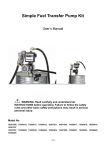
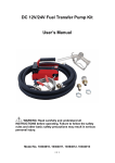
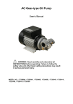
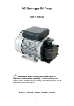
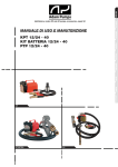
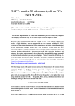
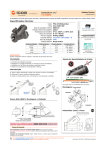
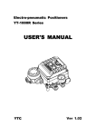
Fuel Transfer Pump Kits
User’s Manual
WARNING: Read carefully and understand all INSTRUCTIONS
before operating. Failure to follow the safety rules and other basic
safety precautions may result in serious personal injury.
Model No.
10305601, 10307202, 10308001, 10305602, 10307203, 10308002,
10306602, 10308202, 10306603, 10308203, 10305627, 10305628, 10307006
1 OF 8
A. DECLARATION OF CONFORMITY
DECLARATION OF CONFORMITY
IN ACCORDANCE WITH THE DIRECTIVES:
89/392/CEE - 91/368/CEE - 93/44/CEE – 89/336/CEE – 92/31/CEE
THE MANUFACTURER:
INTRADIN (SHANGHAI) MACHINERY
118 DUHUI ROAD, MINHANG DISTRICT, SHANGHAI, 201109 CHINA
DECLARES THAT THE FOLLOWING PUMP MODELS:
10305601, 10307202, 10308001, 10305602, 10307203, 10308002, 10306602, 10308202, 10306603, 10308203,
10305627, 10305628, 10307006
To which this declaration refers, conform to the following applicable regulations:
EUROPEAN REGULATIONS:
EN292-1-92 – Safety of Machinery – General Concepts, basic principles for design – terminology, basic
methodology
EN292-2-92 – Safety of Machinery – General Concepts, basic principles for design – specifications and technical
principles
EN294-93 – Safety of Machinery – safe distances to prevent the operator’s upper limbs from reaching dangerous
areas
EN60034-1-2000 – Rotating electrical Machinery – nominal and functional specifications
EN60034-5-2001 – Classification of grades of protection for the housings of rotating electrical machinery
EN61000-6-3 – Electro – magnetic compatibility – generic emission standards
EN61000-6-1 – Electro – magnetic compatibility – generic immunity standards
EN55014-1-00(A1/99-A2/99) limits and methods for measuring radio disturbance characteristics
EN55014-2-97 – Electrical motor – operated and thermal appliances for household and similar purposes, electric
tools and similar electrical apparatus
EN60204-1-98 –safety of machinery – electrical equipment of machines
B. INTRODUCTION
The diesel transfer pump kits have been designed for the delivery of diesel or kerosene from an open surface
tank. This manual, apart from giving all necessary information on ordinary maintenance and supporting engineers
in failure detection and repair, should also give all the information’s needed to fully employ the capacity of the
machine, as well as to the user’s needs.
C. INSTALLATION
Electric connection should be done on a CEI standard socket provided with switch (so it isn’t live when the
connection is done) according to L.46/90 prescriptions.
PRELIMINARY INSPECTIONS
Before the power connection is done, verify the conductors aren’t live and general switches are off.
2 OF 8
DISMANTLING AND DISPOSAL PROCEDURE
The metallic parts which the machine is mainly made of will be dismantled and sent to the steel mills. The fuels in
the tanks of the installation will be collected and sent to an authorized disposer. All plastic and non-degradable
material parts will be separately collected and sent to an authorized disposer or recycled.
SAFETY DEVICES
z General Switch
It is placed on the motor body and allows the operator to set it on standby in a very short time. Once the machine
is stopped, the whole starting procedure can be repeated.
z Mechanical Protections
They are metal protections meant to prevent access to mechanical moving parts, high-temperature parts and live
electric parts.
z Harmful Functions
The noise from the machine is below 70 dB (A).
z FIRE PREVENTION
In case of fire never use water, but extinguishing powders charged with CO2 cat. A-B-C-D only, employing the
extinguishers placed next to the machine. Combustion of paints and plastic parts may produce toxic emissions
(always refer to the security supervisor of the place of installation).
z FOR DC PUMPS
ATTENTION!
1. Extreme operating conditions with working cycles longer than 30 minutes can cause the motor temperature to
rise, thus damaging the motor itself.
2. Each 30-minute working cycle should always be followed by a 30-minute power-off cooling phase.
3. MAXIMUM BY-PASSING TIME: 3 MINUTES.
4. DO NOT RUN DRY OVER 30 SECONDS.
NOTICE: THE VISION IS BUILT PAYING MAXIMUM CARE TO USER’S AND MAINTENANCE ENGINEER’S
SECURITY.
D. TECHNICAL DATA
MODEL
Flow Rate
ELECTRICAL POWER
Model of
Meter
Current
Voltage(V)
Power
10305601
56LPM/15GPM
15111200
AC
230V
370W
10307202
72LPM/19GPM
15111200
AC
230V
450w
10308001
80LPM/22GPM
15111200
AC
230V
450w
10306602
66LPM/18GPM
15111200
AC
120V
370W
10308202
80LPM/22GPM
15111200
AC
120V
450w
10305602
56LPM/15GPM
Not included
AC
230V
370W
10307203
72LPM/19GPM
Not included
AC
230V
450w
10308002
80LPM/22GPM
Not included
AC
230V
450w
10306603
66LPM/18GPM
Not included
AC
120V
450w
3 OF 8
10308203
80LPM/22GPM
Not included
AC
120V
370W
10305627
56LPM/15GPM
Not included
DC
12V
/
10305628
56LPM/15GPM
Not included
DC
24V
/
10307006
35/70LPM
9/18PM
Not included
DC
12/24V
/
E. PRECAUTIONS
During Diesel delivery always wear fuel resistant gloves and always wash hands with water and soap at the
end. Always clean at once fuel stains to avoid slips and/or pollution.
Use particular care with the zones next to the controls.
When cleaning, and specially when removing dust or waste, always wear suitable clothes, if possible use
aspirators only. Always use suitable clothes or protective devices. Never place hands or limbs under moving
parts.
F. SYSTEM DESCRIPTION
Functional Description
The diesel transfer system are hydraulic machine tools which feed with a given capacity (volume) of fluid in the
time unit, a collecting tank, sucking the liquid from an open surface feed tank; the allowed suction lift (geodetic
suction lift Hga) is also a specific characteristic of the pump. The system is composed by complementary
equipment, operating as whole to give a complete service:
z Feeding pump
z Volumetric flow meter (Optional)
z Suction filter
z 4M (13.5ft.) Delivery rubber hose
z Manual dispensing nozzle
MACHINE DESCRIPTION
The diesel transfer unit has been designed and built according to the following standards:
z Electric requirements: EN 60204-1 and EN 60529
z Mechanical requirements: EN 292-1 and EN 292-2; EN 55081-2, EN 55011C/A
z Other requirements 89/392 CEE
G. ALLOWED AND FORBIDDEN USE
This fuel transfer unit has been designed and built for DIESEL & KEROSENE TRANSFER ONLY from reservoirs,
tanks and drums.
It is strictly forbidden to employ it to transfer liquids of different kind as gasoline, explosives and
corrosives (or flammable), alimentary liquids.
The machine isn’t designed for employment in the explosive environment.
Operating the pump is forbidden to children and disabled person.
It is forbidden to employ the unit next to flammable liquids (gasoline, alcohol, etc.).
It is forbidden the employment in closed environments in presence of gasoline, LPG, methane fuelled
vehicles.
4 OF 8
H. TRANSPORT AND UNPACKING
Due to its weight and dimensions, the unit can easily be transported by hand. Control that the package is good
conditions and verify that the unit isn’t damaged. Each failure must be noticed in 10 days from receiving the
machine.
For correct unpacking carefully follow these instructions:
1. Place the case on the ground following the indications on the package.
2. Carefully open the case, remove the machine and place it on the ground or on a steady surface.
3. Control that the machine and its accessories aren’t damaged.
4. Fasten the panel, placing it on the ground or on a steady surface capable of carrying the pump, in a repaired
environment with a temperature between +40℃ and -20℃ well lit and ventilated. For a better employment the
unit should be placed as near as possible to level of liquid to be pumped. (Max. distance 2m)
5. Screw the delivery hose on the fitting of the flow meter and of the filling gun.
6. We suggest using a diesel oil resistant rubber or plastic suction hose; spiral shaped, with minimum as 1”
internal diameter, the same as the union. The hose must be sealed to avoid oil leaks. In case a 4M/13.5ft. or
longer hose is employed we suggest to use the foot valve with filter.
I. USE AND STARTING
POWER GRID ELECTRICAL CONNECTION
The plant must be provided with a safety device of 30mA minimum Din standard. The plug must be connected to
an earthed SHUKO socket. It is forbidden to cut or replace the provided plug.
STARTING
Once the hoses are sealed, the feeding cable is connected and the filling gun is in rest position, the machine can
be started. After placing the hose into the tank and the gun into the filling hole, start the pump, gradually release
the lever and start Diesel oil transfer. Once the filling is done release the control of the gun and switch the pump
off. When the pump isn’t in use disconnect it.
FLOW METER (Optional)
The follow meter shows how many litres of liquid were pumped by the unit. Be aware that this device is not
suitable to measure products for resale.
The mechanical flow meters indicate the partial (resettable) and total (no reset function) of the litres pumped.
Each time the instrument must be reset, turn the knob on the left of the unit until all zeroes are displayed.
Calibration
The meter used in the pumping unit is calibrated at the factory. Calibration is recommended upon initial use, after
disassembly or significant wear. Meter calibration can be easily changed with the procedure hereafter. The
proving container should be at least 50 litre / 13 gallon.
Procedure:
Fill container to a know volume
Turn the calibration screw
+Clockwise to increase the number of liters counted
-Counterclockwise to decrease the number of liters counted
5 OF 8
WARNINGS
1. The gunlock has been provided to make filling easier. It is forbidden to leave the gun unattended to avoid oil
overflow.
2. Don’t operate the machine if there is no liquid inside. Don’t start the pump before connecting suction and
delivery hoses.
3. Once the gun is closed, switch the motor pump off as soon as possible. THE PUMP HAS TO WORK IN
BY-PASS CONDITION FOR SHORT PERIOD: MAXIMUM 3 MINUTES.
4. In case of current losses the pump should be switched off and the plug disconnected.
5. It is strictly forbidden to use the pump with wet hands, barefooted or dipped in water.
6. In case of blackout switch the pump off and disconnect the plug to avoid unexpected starts with liquid
overflow.
7. When transferring from open-air tanks, we suggest to place the machine as far as possible to avoid sprays
and sudden dips which may cause serious damage.
J. MAINTENANCE
Each kind of disassembly should always be carried out when the machine is stopped, the plug is disconnected
and after emptying the pump and the flow meter. For a better operation control every three months that there isn’t
any kind of debris in the flow meter filter.
K. OPERATIONAL PROBLEMS
ACCIDENTS
The pump
work
doesn’t
CAUSES
A) Jammed shaft
B) No electric feeding
REMEDIES
A)
B)
Disconnected the plug; unscrew on the pump,
remove the pump body and clean it inside.
Control that the shaft is now working correctly.
Reassemble the pump.
Control that the plug is correctly connected and
that the socket is live.
The pump works
doesn’t deliver liquid.
The pump sucks air from
the suction hose.
Control the suction hose seal on the pump. Verify that
the hose is completely immersed into the liquid and
free from chokes. Control that the filter is clean.
Remember that the pump can suck up to 4 meters.
The pump works but
the flow meter doesn’t
measure
Dirt inside the flow meter
chamber
Disconnected the plug. Using the flow meter exploded
view as a guide disassembles the faceplate and the
assembly support. Open the chamber and carefully
clean the revolving disk. Reassemble.
L. MECHANICAL RISKS
1. Mechanical parts subject to wear
The blades
The bearing
The rotor
These parts should be replaced with original spare parts by qualified personal only or in authorized service
centres.
6 OF 8
Risks due to extreme temperatures
Remember that a very low temperature can freeze the Diesel oil inside the pump. This situation can cause
serious damage to the motor pump unit.
A very high temperature (about 45℃) may cause the plastic parts in the unit to expand. The unit should thus be
placed in a well-ventilated place and protected from the sun.
M. DIAGRAM
Units with meter
Units without meter
N. PARTS LIST
Units with meter
Part No.
Component description
Quantity
1
Screw M6
4
2
Fuel transfer pump
1
3
O-ring
1
4
Outlet
1
7 OF 8
5
Mechanical Meter
1
6
Screw M8
2
7
Elbow
1
8
Screw M8
4
9
Manual Nozzle
1
10
Housing
1
11
Screw M6
4
12
Washer
4
13
Valve
1
14
Filter
1
15
Inlet
1
16
Fitting
1
Part No.
Component description
Quantity
1
Inlet
1
2
Screw M6
4
3
Fuel transfer pump
1
4
Manual Nozzle
1
5
Outlet
4
6
Elbow
1
7
Housing
1
8
Screw M6
4
9
Washer
4
10
Fitting
1
11
Valve
1
12
Filter
1
Unit without meter
8 OF 8