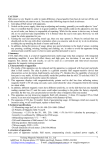
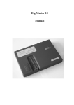
1
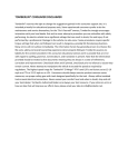
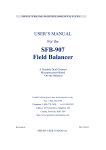
Reliable, Affordable and Durable
Solar-Wind Generators combine the newest wind turbine technology
and market research from years of feedback of owners of small wind turbines.
Our goal is to produce reliable, affordable, and durable solar-wind generators
that will last for years with maintenance free operation.
Wind generators, like other sources of electrical power, must be installed
following the owner’s manual and the guidelines established by state and local
regulations. It is very important for you to read the entire manual thoroughly
prior to installation. Also, please consult a local electrical contractor or the local
planning and zoning office for your area of regulation details.
2
Table of Contents Introduction……………………………………………4
1. Safety Precautions…………………………………...8
2. Parts in the Package………………………………..10
3. Features of the Wind Turbine……………………...12
4. Specifications of the Wind Turbine………………...14
5. Installation Procedures……………………………...16
6. Configuration………………………………………....20
7. Choosing Site…………………………………………22
8. Tower…………………………………………………..23
9. Troubleshooting………………………………………24
10. Maintenance……………………………………......25
11. Warranty Policy.…………………………………….25
12. Contact Us………………………………………….27
3
Introduction Hybrid solar-wind generator system optimizes the use of natural
energy resources combined with cutting-edge technology.
The Optimal Stand‐Alone Power System Many remote towns or sparsely populated areas are not serviced by the
main power grid. Power must be generated locally using engine generators
powered by conventional fuels, such as diesel. However, the transportation
and storage of diesel fuel can be expensive and the supply is not always
reliable. Therefore, diesel generators are best used on a short-term basis or
for emergency purposes. Solar and wind resources are good alternatives to
provide more consistent year-round energy power. Solar and wind are also
the most available renewable energy resources on earth, and many remote
areas have sufficient supply of both.
The sun is the source of all energy on earth. Wind is a form of solar
energy and is caused by the uneven heating of the earth’s surface by the sun.
For example, the poles receive less energy from the sun than does the equator,
and dry land heats up and cools down more quickly than does the seas. On
much of the earth, wind speeds are low in the summer, when the sun shines
brightest and longest. The wind is stronger in winter, when less sunlight is
available to produce electricity from solar cell technology. Wind speeds may
also be lower during the morning and mid day when sunlight is strong, but
increase in the evening when electricity from solar cell technology is less
available. Because the peaks for wind flow and sunlight often occur at
different times of the day and year, wind energy and solar energy can
complement each other. A hybrid solar-wind power system can balance out
the ever-fluctuating solar and wind resources and is more likely to produce
power when you need it.
The Best Combination of Technology Hybrid solar-wind generators produce power from both solar and wind
energy sources. Hybrid solar-wind regulators, which are also known as hybrid
solar-wind charge controllers, regulate the charging current of solar panels and
wind turbines, before it is stored in battery banks. Inverters are then used to
convert direct current (DC) electricity stored in the battery banks to alternating
ARI Renewable Energy Company
4
current (AC). The advantages of solar systems are their reliability and low
operating costs, but they are relatively expensive to manufacture.
Wind power generators use a wind turbine to convert wind energy into
electricity. Similar to solar power systems, charge controllers are used to
regulate the charging current before it is first stored in battery banks, and
inverters are then used to convert DC back into AC. The advantages of wind
power systems are their low manufacturing and operating costs, but their
reliability is sometimes lower due to the fluctuation of air flow.
Non-combined solar systems or wind systems can be affected by
variations in the weather and the season, resulting in inconsistent power
generation. The fluctuations could lead to batteries being under-charged for
a long period of time, causing the lifecycle of the batteries to be shortened.
Since solar power and wind power can complement each other as energy
sources, a hybrid solar/wind power system will optimize the use of these two
natural energy resources for needed power supply. Manufacturing costs of
hybrid systems can be reduced because the same battery bank and inverter
can be used for both the solar and the wind generators.
Advanced Over‐Speed Protection System As the technology of small wind generators has advanced in past decades,
so has the industry. However, the reliability of small wind generators
continues to plague the industry. Due to cost considerations, manufacturers
tend to use mechanical controllers, which are based on simple principles of
ARI Renewable Energy Company
5
aerodynamics, for wind power control, in lieu of the more technologically
advanced and more expensive hydraulic pressure controller. While it could
pass wind turbine tests, a mechanical controller, which has movable parts,
does not work well in the field due to the complexity and rapidity of change in
wind speed and wind direction. The movable mechanical parts invariably wear
out in extreme weather conditions, resulting in a break down of the system.
Since fewer movable parts give less chance for a breakdown, high-quality
wind generators today typically have only three movable parts:
a. Main body of wind turbine
b. Rotor blades
c. Over-speed protection system
The first two movable parts are indispensable because they compose the
core of the wind turbine. In order to increase reliability, we must turn our
attention to the over-speed protection system.
All wind turbines are designed with some kind of over-speed protection
system. In case of strong wind, it is necessary to waste part of the excess
energy of the wind in order to avoid damaging the wind turbine. There are
two different ways to design an over-speed protection system on modern wind
turbines.
a. A pitch-controlled wind turbine that turns blades out of the wind when
the wind output becomes too high and turns them back into the wind
when the wind speed drops.
b. A stall-controlled wind turbine that has blades bolted onto the hub at a
fixed angle. When the wind speed becomes too high, it creates
turbulence on the side of the blades that is not facing the wind. In other
words, a stall, the same way an aircraft wing stalls. This stall reduces
or stops the lifting force of the rotor blade from moving it forward.
However, both approaches have technical problems. Wind flow is a
complex phenomenon. Not only is turbulence a constant occurrence, but the
change of wind speed and direction is instantaneous and frequent. No
mechanical apparatus can react swiftly enough to match the instant change in
wind flow. As a result, the heavy wear and tear often causes the breakdown
of the wind turbine.
We have developed a brand new electromagnetic brake for
wind turbines.
The new technology incorporates an entirely new
magnetoelectricity regulator that functions as a
ARI Renewable Energy Company
6
brake, similar to modern electrical and hybrid cars.
This brand-new regulating protection idea has discarded the mechanical
regulation structure and has fundamentally solved the reliable operational
problem associated with the hybrid solar-wind generator. This advanced
over-speed protection system has the following advantages:
a. It has discarded the mechanical regulator of the wind turbine, and
therefore it only retains two moving parts. This greatly enhances the
structural stability and reliability of the wind turbine.
b. The design of the main body of the wind turbine now has more artistic
and diverse choices when the mechanical regulating structure is
eliminated.
c. The advanced over-speed protection system also gives different levels
of charge control, according to the variable wind speeds, which greatly
increases the performance of the wind turbines.
I. Safety Precautions
The Solar-Wind generator is designed under strict safety regulations.
However, any electrical and/or mechanical equipment during installation or
operation can cause potential inherent dangers, if the proper safety
precautions are not taken. Please read the following solar-wind power
generator safety precautions thoroughly before installing your solar-wind
generator.
1.1 Installation Safety
1.1.1 Rotating blades can move fast enough that the tip of a blade is almost
invisible, which can cause serious injury or damage to anything it
contacts. DO NOT INSTALL THE TURBINE WHERE ANYONE CAN
COME IN CONTACT WITH THE BLADES. DO NOT INSTALL THE
BLADES UNTIL THE TURBINE IS MOUNTED ON THE TOWER.
1.1.2 Undersized wire or a bad connection can cause over-current electrical
dangers and overheating in wiring systems that could cause fire or other
personal dangers. STRICTLY FOLLOW THE INSTRUCTIONS ON THE
WIRE-SIZING CHART IN THIS MANUAL . FUSE ALL CONNECTIONS
AND CHOOSE THE CORRECT SIZE OF FUSE OR CIRCUIT
BREAKER ACCORDING TO THE GUIDELINES OF THIS MANUAL.
1.1.3 It is very important to disconnect all turbine wiring from batteries and
turn the charge controller switch off before installation. Please, carefully
follow the step-by-step installation procedures. Connecting the wires to
the battery prior to the installation of the turbine can cause the rotor to
spin up during installation and result in personal injury. DO NOT
ATTACH THE WIRES TO THE BATTERIES UNTIL THE LAST STEP
OF THE INSTALLATION PROCESS.
1.1.4 During tower set up, under no circumstance should anyone stand near
the construction site. It is important for you to consult with a local
specialized tower installation technician, and you will need someone
available to help during the installation process. The turbine installation
should take place at ground level prior to mounting the turbine to the
tower. DO NOT ALLOW ANY PERSON UNASSOCIATED WITH THE
INSTALLATION TO STAND NEAR THE CONSTRUCTION SITE
DURING THE INSTALLATION PROCESS.
1.2 Operation Safety
1.2.1 Fasten all tower welding, bolts, and nuts and tighten all connections
before operation.
1.2.2 Before regular maintenance or battery replacement, shut down the
turbine by setting the charge controller switch to the “STOP” position.
Do not disconnect the battery wires when the controller is set to “ON”
position.
1.2.3 Caution: The moving rotor blades can be broken, if a solid object comes
in contact with them. After setting the controller switch to the “STOP”
position, you should wait until the blades stop rotating before any
maintenance or inspection of the blades.
1.2.4 The wind turbine is designed to shut down automatically when a
strong wind blows through the site. However, before extreme weather
approaches your area, including but not limited to hurricanes, tornados,
and extreme winds (140 MPH+; 63 m/s), you should lower the tower to
protect from any potential accidents. Before lowering the tower, you
must set the controller switch to the “STOP” position, disconnect the
wires to the battery bank, and make sure the blades stop rotating.
2. Parts in the Package
Please unpack and check the packing list to ensure every part is included
in the packing box.
No.
1
2
3
4
5
6
7
8
9
10
11
12
13
14
15
16
17
18
Part Name
Alternator Main Body
Rotor Shaft
Hub
Rotor Blades
M8*30 Screw
Ф8 Flat Washer
M8 Anti-Loosening Nut
Nose Cone
Nose Cone Cover
M6*45 Screw
Ф 6 Flat Washer
M16*1.5 Nut
Ф16 Spring Pad
M8*15 Screw
Ф8 Flat Washer
M8*15 Nut
Cable Connector
Yaw Shaft
Quantity
1
1
1
3
9
9
9
1
1
1
1
1
1
4
4
4
1
1
3. Features
3.1 Alternator
The wind alternator is made with high quality, high strength permanent
magnetic materials. It is lightweight and compact with high power generating
capacity. Our wind alternator experts have used unique electromagnetic
technology that results in very little starting resistance, thus effectively
guaranteeing the easy startup of the wind turbine even with gentle breezes.
And the alternator is designed to provide efficient AC power with its built-in
electronic control system. The power capacity and startup performance have
made this alternator one of the best in the world.
3.2 Turbine
The turbine’s main body is made of high-quality die cast aluminum
alloy and stainless steel components from a precision casting process. Thus it
is lightweight, yet extremely strong and highly reliable. Because of the
precision casting process, the wind turbine has a perfect shape. Moreover,
the die cast aluminum alloy works as a cooling system for the turbine, by
transferring heat into the wind passing through the turbine. Furthermore, the
wind turbine is easy to install and maintenance-free. Its sculptured artistry
as it adds beauty to the skyline, while providing clean energy for you in sunny
or windy weather.
3.3 Blades
Wind turbine blades are made of fiberglass reinforced composite,
shaped through a high-precision casting process. The fiberglass blades are an
extremely strong material that also has the advantage of stability and quiet
operation. Fiberglass can endure severe weather and environments, such as
storms and exposure to salt water and heat. Fiberglass itself is heat resistant
and corrosion resistant. The material is extensively used in the ship industry in
boat frames, in Olympic sports for pool materials, in the construction industry
as support pillars for mansions, and as high-quality blades for wind turbines.
Due to its high strength, heat and corrosion resistance, fiberglass is the best
choice for propeller materials for the hybrid solar wind generator system.
Rotor blades are meticulously designed by experts in aerodynamics to require
very low wind speeds for startup and electricity generation and a very high
wind energy utilizing ratio. Because of the aerodynamic quality of the blades,
propeller racing can be avoided in all circumstances.
3.4 Charge Controller
The surface of the solar-wind charge controller is made through a
precision casting process with high quality and die cast oxidized-processed
aluminum alloy plate. On the outside of the controller is a digital monitor that
visually displays the process of charging and discharging the battery. Separate
lights on the monitor indicate charging of the battery bank by the solar panels
and by the wind turbine. When solar power is charging the battery banks, the
solar LED lights up, and when the wind power is charging the battery banks,
the wind charging LED lights up.
The charge controller is designed with built-in over-speed protection to
give the wind turbine maximum safety and reliability. Moreover, the charge
controller has a built-in circuit breaker to avoid accidental short circuits of the
battery bank. Furthermore, the charge controller is also designed with a
voltage regulator that monitors and regulates the battery voltage. When the
battery voltage rises above the set point, the CPU automatically shuts off the
turbine and stops the rotor blades from rotating. As a result, the wind turbine
stops generating power, protecting the system. When the CPU senses a
voltage drop, the wind turbine resumes rotating and begins normal charging of
the battery.
4. Specifications
4.1 Technical Data of the Wind Turbine
Model
Start up wind speed
Rated wind speed
Incision wind speed
Survival wind speed
Rated voltage (VDC)
450
750
5 mph
2.3 m/s
26mph
11.8 m/s
6.5 mph
3 m/s
140 mph
63 m/s
5 mph
2.3 m/s
26 mph
12 m/s
6.5 mph
3 m/s
140 mph
63 m/s
12
24
24
48
Rated power (W)
450
750
Max. power (W)
520
880
Blade diameter
4.6 feet
1.4 meters
5.9 feet
1.8 meters
Number of blades
3
Material of blades
Fiberglass reinforced composite
Alternator
Permanent magnet brushless
Charge controller
Hybrid solar-wind controller, charging LED display
Over-speed protection
Aerodynamic effects of the blades
and electromagnetic brake
Electromagnetic brake
Over-current protection
4.2 Output Power Curves of the Wind Turbine
We consider the following criteria for wind speed measurement:
a. The speed of wind varies from moment to moment, so it is not
reliable to rate electricity output based on the wind speed of a
particular moment.
b. The average wind speed varies little from year to year for a given
area. This allows us to calculate annual electricity output with
reasonable accuracy.
c. Based on the formula E=0.2D2V3, energy varies with the third power
of the wind speed. During the year, wind speed varies between
3m/s and 8m/s. Electricity output should be measured based on the
low end of the wind speed instead of the peak speed.
d. Wind generators often have to work in extreme weather conditions
such as in sandstorms, rainstorms, turbulent wind climates, and in
high salt alkaloid environments. To ensure reliability, the turbine must
undergo rigorous testing. Systems that are less costly are usually
under-tested and are therefore less reliable.
4.2.1 450
450 WATT
ARI Renewable Energy Company
14
4.2.2 750
750 WATT
5. Installation Procedures
5.1 Preparation for the Installation
5.1.1 Choose a site for the installation of the Solar Wind Power
Generator system according to the recommendations of this
manual.
5.1.2 Purchase a tower kit, tower pipe, an inverter, battery banks, and
cable wires according to the recommendation of this manual.
Have the tower on site and prepare all the necessary wires,
inverter, and battery banks on site for the installation of the
hybrid solar wind generator system.
5.1.3 If you choose to install solar panels at the same time as
installing the wind turbine, have your solar panels ready at the
site for installation.
5.1.4 Choose calm weather and have someone available to help.
5.1.5 If necessary, find a local eligible solar-wind installer or a certified
wind energy electric technician to help with the installation
process.
5.2 S tep-by-Step Instructions
1. Unpack the packing box. Check the packing list to make sure every
part is included in the packing box.
2. Choose a tower pipe that is at least 8 meters or 26 feet high for the
wind turbine. Have your tower kit ready on the site. Refer to the
Tower Kit User’s Manual to install your tower on the ground. Note:
Please wait to erect the tower.
3. Choose the appropriate size of 3-wire copper cable according to
table 1 below or larger diameter (smaller number on A.W.G
standard). Run the cable from the tower base through the tower
pipe to the top of the tower. From the tower base, gently stretch out
the cable to the charge controller.
Model
450
750
Voltage
12V
24V
24V
48V
50M
16#
18#
16#
19#
100M
15#
17#
15#
18#
≥
13#
16#
13#
16#
NOTE: Table 1 shows the distance from the wind turbine to the
charger controller.
4. Strip the insulation back from each set of the 3-wire cable out of the
tower base. Connect the three wires separately to W1, W2, and W3
on the charge controller.
Note: it does not matter which wire connects to which number. The
three leads from the Turbine are AC and may be hooked up in
any order.
Note: Connecting screws for the controller are easily accessed
by removing the silver nameplate located on the front of the
controller. Please pay close attention to the polarity when inserting
battery connection output leads and PV panel input leads. Make
sure each of the three wires is locked firmly on its position.
5. Set up the battery bank. Depending on the voltages of the batteries
you have chosen, have your batteries connected either in series
connections or parallel connections. Please choose Solar-Wind
compatible batteries. We recommend the rechargeable deep cycle
sealed lead-acid (SLA) gel batteries for the Solar-Wind
generator system. Note: The deep cycle Marine battery is not
recommended. Battery banks should be installed according to the
installation guidelines, and this part of the manual involves the
simple steps of the installation of battery banks. Only use batteries
of the same type and same voltage.
When connecting your battery banks, determine the negative
terminal (anode) and positive terminal (cathode) of batteries or
battery bank.
A. Series connection: Connect each set of battery banks in
series (daisy chained) with its neighboring battery to
achieve voltage increase. For example, connecting two
6-volt batteries in series will achieve 12 volts i.e.
connecting positive terminal of one battery to negative
terminal of next battery creates new battery bank with
higher combined voltage of previous batteries or battery
banks, but with same duration of previous battery or bank.
B. Parallel connection: Connecting multiple sets of batteries
in parallel will maintain the same voltage in new battery
bank, but will multiply power duration capacity. Parallel
connection is often used to increase the duration of
available power from the system and the quantity of
stored power. In parallel connection, two of the same
batteries will generate twice the amp/hours of a single
battery; three batteries will generate three times the
amp/hours, and so on. This will lengthen the time before
your batteries will need to be recharged, resulting in a
longer run time for your appliances.
Caution: Do not reverse the connections of your batteries. Make
sure that the connections between batteries are firm and secure.
6. Connect the battery bank to the charge controller.
NOTE:
1) The size of the 3-wire cable that connects the charge
controller to the battery bank needs to follow or exceed
the recommendation of section 6.2.1. (Refer to table 2.)
Improper wiring size can cause the cable to overheat.
2) Make sure the ends of all wires are connected correctly,
with the positive end to the positive and the negative end
to the negative. Otherwise, the generator system may
work improperly or some parts of the system could burn
out.
3) To test the connection between the charge controller and
the battery bank, turn on the charge controller. Two
digital numbers for voltage and amps will display. Turn off
the charge controller again.
NOTE: IT IS IMPORT
ANT TO TURN OFF THE CHARGE
CONTROLLER BEFORE PROCEEDING TO THE NEXT STEP!
7. Connect the top of the yaw shaft to the main body shaft and firmly
lock the yaw shaft (torque the screw to 4.1~6.8w.m. Do not
over-torque). Pass the 3-wire cable out of the alternator main body
through the pole of the yaw shaft.
NOTE: Make sure the yaw shaft does not cut or scratch the cable.
8. Strip the insulation back from each set of the 3-wire cable out of the
top of the tower pipe. Do the same to the 3-wire cable stretched out
of the yaw shaft, using the cable connector (the pins with male and
female) to connect the 3-wire cable out of the alternator and the
3-wire cable from the top of the tower pipe. Then connect the male
and the female pins together.
9. Take out the three blades. On each of the blades you shall see
three screw holes about 8mm in diameter. If the surface of the
screw hole has a block, it is the front, facing the wind. If the surface
of the screw hole is smooth, it is the back of the blade. Place this
back side of the blade on the hub and lock it with M8*30 screws and
Ф 8 flat washers. Firmly tighten the screws. The blades will move
counterclockwise if they are installed correctly.
10. Place the nose cone to the center of the rotor blades, close it with
the nose cone cover and then lock it with M6*45 screws and Ф 6 flat
washers.
11. Mount the hub onto the rotor shaft, align the screw holes, place the
nut at the end of each screw, and tighten the screw. Make sure the
hub is firmly attached to the rotor shaft.
12. To test if the hub is correctly mounted to the rotor shaft, turn the
charge controller to “ON”. Manually move the hub. If the LED
display on the charge controller shows battery voltage as 1~3V,
then you have correctly connected the hub and all the wiring. NOTE:
At this point, please turn the switch of the charge controller to the
“OFF” position.
NOTE: IT IS IMPORT ANT T O TURN THE SWI TCH OF THE
CHARGE CONTROL LER T O THE “OFF” POSITION BEFORE
YOU PROCEED TO THE NEXT STEP!
13. Mount the wind turbine on the top of the tower by inserting the yaw
shaft into the tower pipe (the end with four holes) and lock the wind
turbine with four of the M8*15 3/8” screws provided with your wind
turbine parts.
14. Erect the tower. Firmly secure the tower with all supports. For tower
installation, please refer to your Tower Kit User’s Manual.
NOTE: In the process of erec ting the tow er, please keep the
switch of the charge controller to the "OFF" position.
15. Connect the solar panel to the charge controller. Please refer to the
following table for the choice of your solar panel.
Wind风力发电机
Turbine
太阳能光伏板
Solar
Panel
Battery 蓄电池
Bank
450
300W
2*120Ah-150Ah
750
400W
4*100Ah-120Ah
The total solar power output Amp, when the solar panels are
ARI Renewable Energy Company
19
connected in parallel, shall not exceed the maximum allowed
capacity of the charge controller (refer to the section 6.2.3).
NOTE: If you plan to install more solar panels to increase the power
output of your solar-wind system, please contact us. We can design
a charge controller that specifically meets the technical requirement
of your solar-wind generator system.
Before making the connection, use a dark cloth to cover the solar
panel.
WARNING: If you do not cover the solar panel with a dark cloth,
under strong sunlight the solar panel could generate enough
voltage to cause injury to the installers.
Make sure to attach the positive wire from the solar panel to the
positive connecting point on the charge controller and the negative
wire to the negative connecting point. (Refer to the diagram below.)
NOTE: Incorrect connection can cause the wires and parts to burn
out.
16. Test the charge controller. Renewable Energy Co. has
designed the charge controller with an LED display. The three
indicating lights separately represent solar, wind, and battery. When
the solar panel generates charging voltage, a solar indicating light
will light up. When the wind turbine generates charging voltage, the
wind indicating light will light up, and when the battery is charging,
the battery indicating light will light up. Turn the switch of the charge
controller to the "ON" position. The LED display will turn on, if every
step of the installation is done correctly.
17. Congratulations! You have now completed the installation process.
ARI Renewable Energy Company
20
6. Configuration
6.1 Basic Circuit of the Hybrid Solar-Wind Generator System
A RI
Wind
Solar Panel
Turbine
ARI
Wind
Solar Panel
Turbine
Use
r
Controller
ON
STOP
Battery
Controller
Battery
Inverter
ON
STOP
6.2 System Configuration of Hybrid Solar-Wind Generator
6.2.1 Battery Bank
For the 450 wind turbine, two 120AH/12V or two 150AH/12V batteries
are recommended, and for the 750 wind turbine, we recommend four
100AH/12V or 120AH/12V batteries. The positive terminal (cathode) of the
battery must be well grounded. Too small diameter of 3-wire cable can
substantially cause electric power loss. For the minimum requirement of
diameters of the cable, please refer to Table 2 below (A.W.G. standard):
ARI Renewable Energy Company
21
Distance
voltage
50M
100M
≤ 100m
≥200m
450
750
12V
24V
48V
12V
24V
48V
A.W.G.
(#)
9
12
15
7
9
14
Diam eter
(mm2)
3.0
2.5
1.5
4.0
3.0
2.5
A.W.G.
(#)
8
11
14
6
8
13
Diameter
(mm2)
4.0
2.5
2.5
6.0
4.0
2.5
A.W.G.
(#)
7
10
13
5
7
12
Diameter
(mm2)
4.0
2.5
2.5
6.0
4.0
2.5
6.2.2 Inverter
An inverter converts the DC power to supply AC power. When power is first
generated by solar PV and wind turbine, it is stored in the batteries as DC
power. It is normally necessary to change it to supply AC power supply with the
use of an inverter. We recommend an inverter 110V 60HZ (or 220V 50HZ).
Inverted watts should equal to 1.3 x watts of your solar-wind generator power
output. For example, if your wind turbine is 750 without solar PV panel,
then you should choose 1000W inverter, i.e., 1000W 24VDC or
48VDC/110VAC 60Hz or 220VAC 50Hz. We recommend a pure sine wave
inverter or modified sine wave inverter for the solar-wind generator
system.
6.2.3 Charge Controller
The Charge Controller has a supplementary function. The solar PV panel
and the wind turbine can simultaneously charge the battery bank. The
charge controller is designed with overcharging protection. It will stop charging
when the battery bank is fully charged. After the storage battery charge is
complete, the wind turbine automatically moves to bypass load and the red
indicating light will turn on. When CPU senses the bypass load, CPU
automatically dumps the excessive power. The following are the specifications
of charge controller:
ARI Renewable Energy Company
22
Model
Maximum
Charging Amp(A)
Maximum
Charging volts(V)
450/12V
35
15.5
450/24V
18
30.5
750/24V
30
30.5
750/48V
15
60
NOTE: When used, the charge controller must be connected to the battery
banks. Otherwise, burn out will occur.
7. Choosing a Site for the Wind Turbine
Site selection is very important for both effective performance and
safe operation of your wind turbine. Because wind power is a cube
function of the wind speed, a 10% increase in wind speed will result
in approximately a 37% increase in the wind power available from
the wind and a similar increase in turbine performance. For
example, wind energy at a wind speed of 5 m/s is twice as much as
wind energy at a wind speed of 4 m/s. And it is always true that as
the tower gets higher off the ground, the wind speed gets stronger.
As a rule of thumb, therefore, your wind turbine will perform better
on a higher tower.
In order to ensure the normal operation of your wind turbine, please
refer to the following rules:
1. The wind turbine will generate greater energy power at a higher
wind speed as the tower gets taller.
2. The wind turbine will be severely damaged and its operational
lifespan can be affected, if it is installed at a site where there is
unstable air flow or severe turbulence. Furthermore, turbulence
can substantially reduce the capacity of the wind turbine to
generate power. Therefore, a site with severe turbulence should
not be chosen, but rather avoided at all costs.
3. The recommended tower height is at least 26 feet above
ground.
Trees and various objects can block air flow. The following data
ARI Renewable Energy Company
23
is provided for your reference:
(1) The tower should be at least 20 feet higher than the highest
obstacle.
(2) The tower should be twice as high as surrounding obstructions
(trees, buildings, etc.) if they must be located close together.
(3) If there are houses or trees in the surrounding area, a good rule
of thumb is to choose a tower site that is at least 15 feet away
from any obstructions around it. Note: A shorter distance
requires less wire as well as reduces the amount of power “lost”
in the wires and voltage drop through the wire.
8. Tower
Towers are made with different materials. They come in all shapes,
sizes and costs in the market. The most common wind turbine towers are
guyed and freestanding towers. NOTE: Radio towers should not be used
for wind turbines.
Renewable Energy Co. has specifically designed a tower kit for
450 and 750 wind turbines. The tower kit is easy to install and
economical. It comes with all the necessary parts and bolts to erect your
tower (except tower pipe). You will need to purchase a fence pipe or tubing
from your local store. Please refer to the Tower Kit User’s Manual,
where you will find demonstrative graphics and step-by-step instructions.
Read your manual thoroughly before you begin to assemble your tower kit.
Evaluate your site to determine the appropriate tower height and
available acres to install a tower. Consider the quantity of wind turbines
you will install and the cost of the tower. Choose one that fits your budget
and the availability of space on your property.
24
9. Troubleshooting
Problem
Blades do not spin
or move slowly
Possible Cause
1) The blades are not locked tightly
to the hub.
2) The blades are reversed and
installed upside down.
3) The height of the tower is less
than 8m,and surrounding trees
and buildings have blocked the
flow of wind.
4) Short-circuit of the wiring from
the alternator has caused
electromagnetic brake, which
leads the blades to slow down.
ARI Renewable Energy Company
Solution
Follow these steps:
1)Tighten the screws and make
sure the blades are locked tightly
to the hub.
2)Make sure the blades are
installed correctly and are not
reversed or upside down.
3)Increase the height of the tower;
make sure the top of the tower is
above the surrounding trees and
buildings.
4)Contact our company for
possible wiring short circuits.
25
Turbine is not
charging or the
battery voltage is
too low.
1) Solar panel, wind turbine, or
battery bank incorrectly
connected to the charge
controller.
2) Before erecting the tower, you
connected the alternator to the
charge controller but did not turn
the switch of the charge
controller to the “OFF” position
to prevent the wind turbine
working, which caused an
accidental short-circuit of the
charge controller.
3) You accidentally scratched the
cable wires during installation,
which caused a short circuit or
shuts.
4) A bad battery or an improper
battery size was used. One bad
battery can cause high voltage
and prevent the turbine from
charging.
1)Check the connections from the
charge controller to the battery
bank, solar panel, and wind
turbine, and make sure all the
wirings are correctly connected
according to this manual, with
positive to positive and negative to
negative.
2)If a short circuit has caused the
turbine from charging, please
contact us.
3)Ask a certified electrical
technician to examine the
problem.
4)Make sure you have followed
the recommendation of this
manual in choosing proper
batteries for your wind turbine and
the positive terminal (cathode) of
the battery is well connected.
Note: please choose deep cycle
SLA gel batteries.
10. Maintenance
The wind turbine is highly reliable and does not need regular
maintenance. However, the overall system of wind turbine – tower – power
transmission cables must be inspected and maintained regularly to ensure the
system’s normal operation.
(1) Check the tower cables for loosening and fasten any loosened wiring in
a timely manner. Carry out this inspection multiple times in the initial
three months after tower erection. It is also necessary to check wiring
after high winds.
(2) Check to see if various connecting points of the wires are
well-connected or are corroded.
(3) Regularly check and maintain the battery bank as per the maintenance
requirements of the batteries.
(4) It is recommended that you lay down the tower in the case of
ARI Renewable Energy Company
26
approaching extremely rough weather (such as typhoons or hurricanes)
to avoid accidents.
11. Warranty Policy and Procedures
11.1 What is Covered and Warranty Terms:
(1) Dead on Arrival (DOA): Within the first thirty (30) days from the
shipment date, any DOA unit will be replaced with a new wind turbine.
(2) Defective Parts: Within the first one (1) year from the shipment date,
any defective part will be replaced at no charge.
11.2 What is NOT Covered
(1) Damage due to lightning and extreme weather (including but not limited
to hurricanes and tornados).
(2) Damage due to extreme winds (110 MPH+; 60 m/s).
(3) Damage due to improper installation (including but not limited to
improperly choosing a site, poor tower design and inverted hanging).
ARI Renewable Energy Company
27
(4) Damage due to modification of the wind turbine or replacing parts with
nonoriginal parts NOT provided by
.
(5) Damage due to improperly wiring to batteries.
(6) Damage to blades due to flying debris.
(7) Damage due to neglecting to follow the maintenance recommended in
this manual or compromising the safety of the machine.
(8) Any consumable materials (including but not limited to indicating lamp,
gasket, fuse, and electronic brush).
11.3 Procedures
(1) Write the serial number on the front of this manual and keep your
receipt or invoice with this manual. You will need them in the case of
filing a claim.
(2) In the event of a wind turbine failure or if there are defective parts,
please contact your dealer to
obtain a Return Material Authorization (RMA) number. All returned unit
must have a valid RMA number. Please do not return any unit until
you receive a RMA number.
We reserves the right to refuse shipments that do not have an authorized RMA
number. Refused shipments will be returned to the shipper via collect
freight.
(3) For a Dead on Arrival (DOA) unit, you must provide the serial number
for the wind turbine and a copy of the receipt or the invoice to the claim
department. DOA unit must be returned within ten (10) days from
receipt of RMA issuance and a prepaid shipping label. A new wind
turbine will be shipped from a dsignated manufacturing facility of within a few
business days of receipt of DOA unit.
(4) For defective parts, the customer must provide the serial number of the
wind turbine, a copy of the receipt or the invoice of purchase, and a
detailed description (photos, if necessary) of the defective parts to the
claim department. A wind turbine technician or a designated repair
manufacturing facility is the only
source capable of determining a defective part. Upon receipt of the
information, we will either issue an RMA
number or refuse the claim once the cause of the defective parts is
determined.
(5) Defective parts must be returned within ten (10) days from receipt of
RMA issuance for replacement. New parts will be shipped within two (2)
business days of the receipt of the defective parts.
(6) Upon determine the cause of the defective parts, the claim department
ARI Renewable Energy Company
28
may allow a customer to return
the whole wind turbine for repair. In this case, the customer must
return the wind turbine within ten (10) days from receipt of RMA
issuance if the repair is granted.
(7) The customer will be responsible for shipping the parts for replacement
or turbine for repair. will ship the
repaired turbine back to the customer using the lowest shipping cost
available. If faster shipping is requested, the customer is responsible
for paying the difference.
12. Contact Us
ARI Renewable Energy Company
29
Thanks for your Purchase!
ARI Renewable Energy Company
30