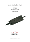
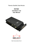
Download Installation & User Manual
Transcript
RST425
Short Burst Data Modem
Installation & User Manual
Beam Communications Pty Ltd
RST425 INSTALLATION & USER MANUAL
RST425
Installation and
User Manual
Beam Communications Pty Ltd
8 Anzed Court, Mulgrave,
Victoria, 3170, AUSTRALIA
Information furnished by Beam Communications Pty Ltd (Beam) is believed to be accurate and
reliable. However, no responsibility is assumed by Beam for its use, or for any infringement of
patents or other rights of third parties, which may result from its use. No license is granted by
implication or otherwise under any patent or patent rights of Beam. Beam reserves the right to
change specifications at any time without notice.
Copyright © 2008 Beam Communications Pty Ltd. All rights reserved
Product name: RST425 Installation & User Manual
Manual revision: 02
Part Number USRMAN003702
Issue Date: July 2008
2
RST425 INSTALLATION & USER MANUAL
Content
RS232 PORT ELECTRICAL PARAMETERS ....... 12
DATA CONNECTIVITY ....................................... 13
CONFIGURATION SETTINGS .............................. 13
Modes of Operation ..................................... 13
SERIAL PORT SIGNAL LEVELS ............................ 14
Data Port Inputs .......................................... 14
Data Port Outputs........................................ 14
HARDWARE FAILURE REPORTING..................... 14
SAFETY INFORMATION................................... 4
ABOUT BEAM COMMUNICATIONS .............. 5
WHAT IS THE RST425? ................................... 6
PACKAGE CONTENTS ......................................... 6
OPTIONAL BEAM ACCESSORIES ........................ 6
INSTALLING THE RST425............................... 7
CONNECTING THE ANTENNA CABLE .................. 7
CONNECTING THE POWER CABLE AND SERIAL
CABLES .............................................................. 8
DIMENSIONS AND MOUNTING ............................ 9
RF INTERFACE................................................ 15
SPECIFICATION SUMMARY ......................... 10
TROUBLESHOOTING THE RST................... 16
RS232 SPECIFICATION ................................. 11
BEAM WARRANTY CONDITIONS ............... 17
PHYSICAL CONNECTION .................................. 11
RS232 PORT SIGNAL SUPPORT AND
HANDSHAKING.................................................. 11
9-Wire and 3-Wire Operation ...................... 11
USER / INSTALLER INFORMATION ......... 18
ANTENNA CONNECTOR ..................................... 15
Antenna Connector Type.............................. 15
RADIO CHARACTERISTICS ................................ 15
CONVENTIONS IN THIS MANUAL
Warnings, cautions and notes appear throughout this manual.
They are represented by following conventions.
Warning: This symbol and associated text indicate a warning note
providing information to prevent personal injury or damage to
equipment.
Note: This symbol and associated text indicate a note providing
general operating information.
Interference: All wireless phones may get interference, which could
affect performance.
3
Safety Information
Note: Read the following information before installing and using the
BEAM RST425.
Your RST425 is a low power radio transmitter and receiver. When it is ON, it receives
and sends out radio frequency (RF) signals.
The design of your RST425 system complies with international safety standards.
Refer to the appropriate section of the RST425 User Manual for additional relevant
safety information.
Warning:
Do not open equipment. There are no user-serviceable parts inside.
If a DC power supply is to be used, its output must comply with the Safety
Extra Low Voltage (SELV) requirements of IEC60950.
All connectors except the Line and Accessory sockets must only be
connected to equipment ports which comply with the Safety Extra Low
Voltage (SELV) requirements of IEC60950.”
4
About BEAM Communications
Beam Communications, is an authorised manufacturer of Iridium Satellite products.
Beam develops subscriber products that utilise the Iridium satellite network of Low
Earth Orbit satellites, known as LEOs. The Iridium network is extensively used
around the world by commercial enterprises and defence agencies.
Beam products address the needs of individuals, communities, government agencies
and the corporate sector, providing voice and data access without the need for
traditional wire-line or mobile phone infrastructure.
As the Iridium satellite network is global, Beam’s products address global markets,
across the spectrum of rural and remote users, including households, motor vehicles,
telemetry, maritime and emergency services.
Beam Communications Pty Ltd
8 Anzed Court, Mulgrave,
Victoria, 3170, AUSTRALIA
Web:
www.beamcommunications.com
Info:
[email protected]
Support:
[email protected]
Tel:
+61 3 8851 0400
Fax:
+61 3 9560 9055
5
What is the RST425?
The RST425 is a Remote Satellite Short Burst Data only modem designed to provide
a reliable and cost effective means of Iridium SBD development.
It utilizes the Iridium SBD (Short Burst Data) module and provides a female D9
RS232 connector, for direct connection to a PC.
Key Features:
•
Small form Factor
•
No SIM Card Required
•
Maximum mobile originated message size of 340 bytes
•
Maximum mobile terminated message size of 270 bytes
•
Visual indication of network availability
Package Contents
The RST425 package contains:
•
1 x RST425 Short Burst Data Modem
•
1 x DC External Cable [CBLASY001602]
•
1 x TNC-F to SMA-M coaxial adaptor [TNCF-SMAM]
•
1 x Serial Data Cable DB9M to DB9F [CBLASY005501]
•
1 x Resources CD (includes User Manual) [CDROM0001xx]
Optional Beam Accessories
RST910
Fixed Mast Antenna
RST915
Magnetic Mount Antenna
RST920
Bolt Mount Antenna
RST985
Serial to USB Converter Cable
See your Service Provider for pricing and availability of these optional accessories
6
Installing the RST425
Connecting the Antenna Cable
1. Screw the TNC-F to SMA-M coaxial adaptor onto the antenna jack located on
the back end of the module.
2. Ensure that the cable being used is long enough to reach from the RST425 to
the Antenna location. Plug the antenna cable into the adapter.
3. Ensure that you fasten the antenna cable securely to the TNC jack by
screwing the cable firmly all the way in with your fingers.
4. Please refer to the Antenna Installation Guide for important information on
installation and placement of your antenna.
Note: Refer to the Antenna Installation Guide supplied with your RST425 for information on
installing the antenna and assuring Quality of Service.
This guide is also available for download at www.beamcommunications.com
7
Connecting the Power Cable and Serial Cables
The module is powered from a 9 to 32V DC supply using a 2-pin circular-ring
connector from the supplied cable. Attach the 4mm eyelets to a compliant power
supply. The positive terminal is identified by a RED sleeve over eyelet.
The front LED has a dual function:
Green – Power OK and network visible.
Orange – Power OK but network unavailable.
The 9-pin D-Connector provides the Communications Serial port to the RST425
terminal. This connects directly to a Computer or communicating terminal device.
The default baud rate is 19200 8N1. The RST425 does not have an autobaud
facility. The baud rate can be set via the AT+IPR=n where n is one of the following.
N
BAUD
1
600
2
1200
3
2400
4
4800
5
9600
6
19200 (default)
7
38400
8
57600
9
115200
[Refer to the ISU AT Command Reference for other available AT commands].
8
Dimensions and Mounting
9
Specification Summary
RST425
Electrical
Power
9 – 32 VDC, 2A
Plug-pack (if provided)
90-250VAC 50/60Hz input
Power Consumption (Average)
Standby Mode
0.4W
Transmit Mode Peak
1.8W
Modem Type
SBD Data only
Speed
2400 bps
EMC Compliance
CE
Environmental
Operating Temperature Range
-35°C to +70°C ambient
Operating Humidity Range
<85% RH non-condensing
Storage temperature
-40C to +85C
Weight
0.5 kg
Dimensions
160 x 93 x 30mm
RF Interface (SBD Transceiver)
Frequency range
Peak Power
9W (max)
Average Power
1.75 W (During message transfer)
Standby Power
Receiver Sensitivity
0.33W
Receiver Spurious Rejection
offsets > 1 MHz (typical)
1616MHz to 1626.5MHz
-118.5 dBm at 50W (typical)
at
60 dB
Multiplexing method
TDMA / FDMA
Oscillator stability
±1.5ppm
Input/output impedance
50 Ohms – TNC F Connector
10
RS232 Specification
The RST425 is provided with an RS232 serial port for data connection. The 9-pin Dtype (female) sockets, wired DCE for connection to a standard PC with a 1:1 cable.
Physical Connection
The pin-out of both connectors is described in the following table:
Pin
Signal
Direction
Description
1
DCD
RST ¼ PC
Data Carrier Detect (Driven ON at all times)
2
RXD
RST ¼ PC
Received Data
3
TXD
PC ¼ RST
Transmitted Data
4
DTR
PC ¼ RST
Date Terminal Ready
5
GND
6
DSR
RST ¼ PC
Data Set Ready (CTS and DCD)
7
RTS
PC ¼ RST
Request to Send
8
CTS
PC ¼ RST
Clear to Send
9
RI
RST ¼ PC
Ring Indicate
Signal Ground (Common)
RS232 Port Signal Support and Handshaking
The Serial data interface is used to both command the RST425 and transfer user data to and from the
Transceiver. The RST425 presents a 9-wire data port to the FA (Field Application), where the
interface is at RS232 levels. With respect to this interface, the RST425 behaves as a DCE (Data
Communication Equipment), and the FA behaves as a DTE (Data Terminal Equipment).
The terms “FA”and “DTE” are used interchangeably throughout this document; similarly for the term
“DCE”.
Autobaud is not supported in RST425 SBD Transceiver. The baud rate can be set via the AT+IPR
command. The default rate is 19200 bps.
9-Wire and 3-Wire Operation
By default, the serial interface operates as a 9-wire connection. Table 9 describes each of the signals,
where “input” means an input to the RST425, and “output” means an output from the RST425 SBD
Transceiver.
l Description
RXD - Active high data output [The DTE receives the data from the RST425].
TXD - Active high data input [Data is transmitted from the DTE to the RST425].
GND - 0V.
RTS - Active low flow control input.
CTS - Active low flow control output RTS and CTS are used together to implement hardware
flow control when enabled with AT&K3.
DTR - Active low handshaking input AT&Dn controls how the RST425 uses DTR:
If set to AT&D0, DTR is always ignored. Otherwise DTR set to OFF places the data port into
UART test mode after 10 seconds, or immediately on boot-up. A subsequent transition of DTR
to ON returns the data port to DCE mode and resets it to its power-on state.
The UART test mode is provided for factory testing of the data port UART. An FA
should never activate test mode; if it does, the RST425 will stop responding to AT
11
commands until the data port is returned to DCE mode.
DSR - Active low handshaking output.
The RST425 drives DSR ON when the data port is in DCE mode, and OFF when the data port
is in test mode. The DTE may use this signal as an indication that the RST425 is powered up
and ready to receive AT commands.
RI - Active low ring indicator output.
The RST425 drives RI ON when it receives a Automatic Notification from the network that
a Mobile Terminated SBD Message is queued at the Gateway, and drives RI OFF
after 5 seconds or when the DTE initiates an SBD session, whichever occurs first.
DCD - Active low handshaking output.
DCD is driven OFF at all times.
Note: the Ring Indicator (RI) pin is used by the RST425 SBD
Transceiver to indicate that a Mobile Terminated SBD (MT-SBD)
message is queued at the Gateway. The Field Application can monitor
this pin and use appropriate AT Commands to command the
Transceiver to retrieve the MT-SBD message.
The serial interface may be operated with a 3-wire connection, where only transmit, receive and
ground signals are used. However the 9 wire interface offers better control and is the recommended
implementation. Iridium is only able to provide limited 3-wire interface support. When operating with a
3wire connection, the following rules apply:
AT&Dn must be set to AT&D0 to ignore the DTR input
AT&Kn must be set to AT&K0 to disable RTS/CTS flow control
The other output signals may be connected, and operate as follows:
• CTS driven ON (low)
• DSR operates as normal
• RI operates as normal
• DCD driven ON (low)
o
o
o
Note: RTS/CTS flow control, when enabled, is only used when the
data port is in SBD data mode. In AT command mode, RTS is ignored
and CTS is driven ON (low).
RS232 Port Electrical Parameters
The LBT Data Port conforms to the RS232 interface specification with the following
parameters:
1
Parameter
Specification
Communication Rate
220 to 115,200 Baud
Protocol
1 start bit, 8 data bits, no parity, 1 stop bit, asynchronous.
Voltage Levels and Sensitivity
RS232 compliant
1
Autobaud is not supported in RST425 SBD Transceiver. The baud rate can be set via the AT+IPR command. The
default rate is 19200 bps
12
Data Connectivity
To connect your RST425 to a PC or laptop, simply connect the 9-pin serial plug from
your RST425 interface cable to a 9-pin (Male) port on your PC or laptop.
If you do not have a serial port on your PC / laptop, an RST985 Serial to USB
Converter Cable is available from your supplier.
Please refer to the following documents (on CDROM) for correct operation of Short
Burst Data functionality:
“Beam SBD Developer Guide”
“ISU AT Command Reference”
“Iridium SBD IP Socket White Paper”
For more information, please visit www.beamcommunications.com
Configuration Settings
The RST425 allows the DTE to configure the data port communication parameters. The three
configuration types are active, factory default, and stored. The active configuration is the set of
parameters currently in use. They can be changed by the DTE individually via specific AT commands.
The factory default configuration is stored in permanent memory. This configuration can be recalled at
any time through use of the AT&Fn command.
Two groups of settings, or “profiles” can be stored as user-defined configurations. The DTE first
creates desired active configurations and then writes them to memory using the AT&Wn command.
These profiles can be designated to be loaded as the active configuration upon RST425 power-up
through use of the AT&Yn command. The RST425 can be reset without loss of power to these profiles
through use of the ATZn command. These profiles can be designated to be loaded as the active
configuration upon RST425 power-up through use of the AT&Yn command. The RST425 can be reset
without loss of power to these profiles through use of the ATZn command.
The configuration settings are stored in “S-register” locations.
Modes of Operation
The serial interface is always in one of three modes: command mode, SBD data mode or SBD session
mode. When the data port is in command mode, AT commands can be entered to control the RST425.
In command mode, flow control has no effect, with the RTS input ignored and the CTS output driven
ON (low). When in SBD data mode, the RST425 is transferring binary or text SBD message data to or
from the DTE.
In SBD data mode:
• All characters from the DTE not forming part of the message data are ignored (i.e. no
AT commands may be entered).
• No unsolicited result codes are issued.
• RTS/CTS flow control, if enabled, is active. When RTS is OFF (high), the RST425
suspends transfer of data to the DTE; when CTS is OFF (high), the RST425 expects
the DTE to suspend transfer of data to the RST425.
When in SBD session mode, the RST425 is attempting to conduct an SBD session with the network.
In SBD session mode:
• The DTE must wait for the +SBDI session result code.
• All characters from the DTE are ignored.
• Unsolicited result codes are issued where those codes have been enabled.
Transitions between the modes of operation are performed automatically by the RST425 in response
to the SBD AT Commands; the DTE has no other control over the mode.
13
Serial port signal levels
Data Port Inputs
The inputs on the RST425 serial port (RTS, DTR and TXD) will operate correctly at TTL signal levels
(logic low 0.4 V max, logic high 2.4V min) or RS-232 levels up to +/- 25 Volts. Because the circuit for
the data port is an RS-232 receiver the lowest logic low and highest logic high are rated to +/- 25
Volts. The transition voltage point (transition from a Low to a High is at about 1V (Above 1V = a high;
below 1V = Low).
RS-232 transmitters and receivers always invert. Thus if you use these inputs at logic level you would
need to invert these signals using logic-level inverters.
Data Port Outputs
The five outputs from the RST425 serial port (DCD, DSR, CTS, RI and RXD) are all at RS-232 levels
of approximately +/- 7 Volts no load (manufacturing test limits are 6 to 8 Volts). With a 3 kOhm load
the output is +/- 6.4 Volts.
Hardware Failure Reporting
If the RST425 detects a hardware problem during initialization, the RST425 may be unable to function
correctly. The RST425 notifies the DTE of this situation by issuing an unsolicited result code at the
end of initialization:
HARDWARE FAILURE: <subsys>,<error>
where <subsys> identifies the software subsystem that detected the error, and <error> is the
subsystem-specific error code.
Any AT commands that cannot be handled in the failure condition will terminate with result code 4
(“ERROR”).
14
RF Interface
This section describes the physical connector and RF specifications of the RF Interface.
Antenna Connector
The RST425 will have the following antenna connector characteristics:
Parameter Value
Impedance Gain Polarization VSWR (maximum operational) -
50 Ohms nominal
3dBi
RHCP
1.5 : 1
Note: Existing qualified Iridium antennas may be used. (i.e. antennas
designed for the 9522 and 9522A)
Antenna Connector Type
The antenna connector on the RST425 is a female SMA type. An SMA to TNC adapter is also
provided, and can be utilized to suit the type antenna cable connector used.
Radio Characteristics
The tables within this section contain radio characteristics of the RST425 SBD Transceiver.
Parameter Value
Average Power during a transmit slot (max):
1.6 W
Receiver sensitivity:
-118dBm
Max Cable loss permitted (Note 1):
2dB
Link Margin –Downlink (Note 2):
13dB
Link Margin –Uplink (Note 2):
7dB
NOTE 1:
Cable losses should be minimized. Note that the total
implementation loss for an antenna, connectors, cable, lightening
arrestor and any other RF component between the transceiver
and the antenna shall not exceed 3dB. Implementation loss higher
than this will affect link performance and quality of service.
Solutions with a loss higher than 3dB will not meet the
requirements of Iridium Solution Certification.
NOTE 2:
Link Margin given for free space.
15
Troubleshooting the RST
This chapter provides information to help you troubleshoot problems you may
encounter while running the RST425.
Q
No power on RST425 (LED is off)
A
Check power is connected and correct DC voltage is available
Q
RST425 fails to find Iridium service (LED is Orange)
A
Check power connection
Check Antenna connection and location
Q
PC cannot connect to RST425
A
Check that the correct cable is used on the correct port, and
that the bit rate is set the same for both PC and RST425
16
Beam Warranty Conditions
Beam Communications gives this express warranty (along with extended warranty endorsements,
where applicable) in lieu of all other warranties, express or implied, including (without limitation),
warranties of merchantability and fitness for a particular purpose. This constitutes our sole
warranty and obligation with regard to our products as well as the Customer’s sole remedy.
Beam Communications expressly disclaims all liability and responsibility for any special, indirect
or consequential damages or any further loss of any kind whatsoever resulting from the use of our
product(s). The Customer’s sole and exclusive remedy and the limit of Beam’s liability for any loss
whatsoever, shall not exceed the purchase price paid by the Customer for the product to which a
claim is made.
1.
2.
3.
4.
5.
6.
7.
8.
9.
All products manufactured by Beam Communications are warranted to be free from defects in
material and workmanship in accordance with and subject to the following terms and conditions:
This warranty is limited to the original Customer only. It cannot be transferred or assigned to third
parties unless the intent to transfer to a third party is expressly indicated in a purchase order
and/or warranty-processing arrangements have been agreed upon in writing by Beam.
Beam Communications does not warrant any installation, maintenance or service of the Products
not performed by Beam, nor does it warrant the use of Products with unapproved ancillary
products.
Beam Communications will correct any defects in material or workmanship of products
manufactured by Beam which appear within (12) months, from the date of shipment by Beam
Communications to the Customer. Beam Communications will repair or replace, at our option, any
defective product, provided that our analysis and/or inspection discloses that such defects
developed under normal and proper use.
This warranty does not extend to goods subjected to liquid or particulate ingress, extreme
humidity, misuse, neglect, accident or improper installation, or to maintenance or repair of
products that have been altered or repaired by anyone except Beam Communications unless
otherwise stated in writing.
The warranty is a return-to-base warranty and freight is paid by the sender.
A charge of USD150 including return freight will be made for testing returned product which is not
defective or is found to be defective as the result of improper use, maintenance or neglect.
Beam Communications will not accept responsibility for any invoiced goods or services that are
not covered by a Beam Communications written purchase order. Under no circumstances does
Beam Communications agree to pay for labour or other related expenses associated with the
troubleshooting and/or repair of our product without prior specific written authorization.
Information in our descriptive literature is based on product specifications that are current at the
time of publication. Product specifications, designs and descriptive literature are subject to change
as improvements are introduced. Although we announce changes as they occur, we cannot
guarantee notification to every Customer. Beam Communications warrants delivered product to
conform to the most current specifications, designs and descriptive literature.
This warranty policy may be expanded or limited, for particular categories of products or
Customers, by information sheets published as deemed appropriate by Beam Communications. In
particular, the warranty for third party Products is that of the third party and not Beams warranty.
17
USER / INSTALLER INFORMATION
"
Please record your serial number here for future reference:
BEAM SBD Modem
Model:
Serial no.:
RST425
#
This number can be copied from the white shipping label on the RST425 box
Eg. RTK02833
Installation Location:
Installation Date:
Installation Technician:
Place Of Purchase:
18


