1
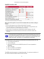
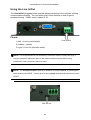
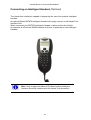
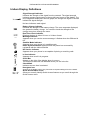
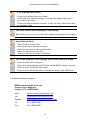
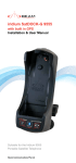
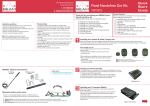
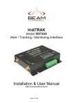
SatDOCK RST980 Installation & User Manual Suitable for the Iridium 9505A Portable Satellite Telephone RST980 Installation & User Manual Beam Communications Pty. Ltd. SatDOCK RST980 Installation and User Manual Version 3 BEAM Communications Pty Ltd 8 Anzed Court, Mulgrave, Victoria, 3170, AUSTRALIA Information furnished by BEAM Communications Pty Ltd (BEAM) is believed to be accurate and reliable. However, no responsibility is assumed by BEAM for its use, or for any infringement of patents or other rights of third parties, which may result from its use. No license is granted by implication or otherwise under any patent or patent rights of BEAM. BEAM reserves the right to change specifications at any time without notice. Copyright © 2008 BEAM Communications Pty Ltd. All rights reserved Product name: RST980 SatDOCK Manual revision: 03 Part Number: USRMAN003203 Release date: June 2008 2 RST980 Installation & User Manual Package Contents Check that your RST980 SatDOCK package contains: 1 x RST980 SatDOCK Docking Station 1 x Hands Free Interface (HFI) module 1 x Speaker 1 x Microphone 1 x Interface Cable (from HFI to SatDOCK) 1 x 3-wire Power cable harness / 2 Fuses 1 x “Iridium Antenna Guide” (printed) 1 x RAM bracket 1 x SMA / TNC Adapter 2 x M4 Screws Optional Accessories The following optional accessories are available for your RST980. • Intelligent handset (uses RJ45 port) • Antenna Cable • Antenna See your Service Provider for pricing and availability of these quality BEAM accessories. 3 RST980 Installation & User Manual User information " Please record your serial number here for future reference: Model: RST980 Serial no.: # This number can be copied from the white label on the SatDOCK Eg. 100A2800 4 RST980 Installation & User Manual Contents Package Contents .....................................................................................................3 User information........................................................................................................4 Safety Information .....................................................................................................6 About BEAM Communications...............................................................................10 About this equipment..............................................................................................11 Installation Guidelines ............................................................................................14 Installation Procedure................................................................................................15 Wiring for Additional Features ...................................................................................22 Using the Communication Port ..............................................................................28 RS232 Data Port .......................................................................................................28 Using the Line In/Out.................................................................................................29 Connecting an Intelligent Handset (Optional) ............................................................30 Power-On Messages .................................................................................................32 Assuring Quality of Iridium Service.......................................................................33 Specification Summary ...........................................................................................35 Cradle Mounting DimensionsTroubleshooting.....................................................37 Troubleshooting ......................................................................................................38 5 RST980 Installation & User Manual Safety Information Note: Read the following information before installing and using the BEAM RST980 SatDOCK. Your RST980 is a low power docking station for the 9505A handset; when ON, it will charge the 9505A handset whilst docked in the RST980. The design of your RST980 system complies with international safety standards. Refer to the appropriate section of this RST980 Installation & User Manual for additional safety information. Warning: Do not open equipment. There are no user-serviceable parts inside. If a DC power supply is to be used, its output must comply with the Safety Extra Low Voltage (SELV) requirements of IEC60950. All connectors except the Line and Accessory sockets must only be connected to equipment ports which comply with the Safety Extra Low Voltage (SELV) requirements of IEC60950.” Conventions in this Manual Warnings, cautions and notes appear throughout this manual and are represented by following conventions. Warning: This symbol and associated text indicate a warning note providing information to prevent personal injury or damage to equipment. Note: This symbol and associated text indicate a note providing general operating information. Interference: All wireless phones may get interference, which could affect performance. " Record: Write details of your unit for easy reference when required. Ideal when troubleshooting. 6 RST980 Installation & User Manual Exposure to Radio Frequency Signals Your wireless mobile telephone is a low power radio transmitter and receiver. When it is ON, it receives and also sends out radio frequency (RF) signals. International agencies have set standards and recommendations for the protection of public exposure to RF electromagnetic energy. • International Commission on Non-Ionizing Radiation Protection (ICNIRP) 1996 • Verband Deutscher Elektrotechniker (VDE) DIN-0848 • United States Federal Commission, Radio Frequency Exposure Guidelines (1996) • National Radiological Protection Board of the United Kingdom, GS 11, 1988 • American National Standards Institute (ANSI) IEEE. C95. 1-1992 These standards are based on extensive scientific review. For example, over 120 scientists, engineers, and physicians from universities, government health agencies, and industry reviewed the available body of research to develop the updated ANSI standard. Antenna Care Use only the supplied or an approved replacement antenna. Unauthorized antennas, modifications, or attachments could damage the phone and may violate local agency regulations. Please refer to your Service Provider for further information. Phone Operation Do not operate your mobile telephone when a person is within 4 inches (10 cm) of the antenna. A person or object within 4 inches (10 cm) of the antenna could impair call quality and may cause the phone to operate at a higher power level than necessary and expose that person to RF energy in excess of that established by the FCC RF Exposure Guidelines. Driving Check the laws and regulations on the use of wireless telephones in the areas where you drive. Always obey them. Observe the following guidelines when using your phone while driving. ¾ ¾ ¾ Give full attention to driving—driving safely is your first responsibility. Use hands-free phone operation, as provided by this kit Turn off the road and park before making or answering a call if driving conditions so require. 7 RST980 Installation & User Manual Electronic Devices Most modern electronic equipment is shielded from RF signals. However, certain equipment may not be shielded against the RF signals from your wireless phone. Pacemakers The Health Industry Manufacturers Association recommends that a minimum separation of six inches (6") be maintained between a wireless phone’s antenna and a pacemaker to avoid potential interference with the pacemaker. These recommendations are consistent with the independent research by and recommendations of Wireless Technology Research. Persons with pacemakers: ¾ Should ALWAYS keep the phone more than six inches from their pacemaker when phone is turned ON ¾ Should turn the phone OFF immediately if you have any reason to suspect interference is taking place Other Medical Devices If you use any other personal medical device, consult the manufacturer of your device to determine if it is adequately shielded from external RF energy. Your physician may be able to assist you in obtaining this information. Turn your phone OFF in health care facilities when any regulations posted in these areas instruct you to do so. Hospitals or health care facilities may be using equipment that could be sensitive to external RF energy. Vehicles RF signals may affect improperly installed or inadequately shielded electronic systems in motor vehicles. Check with the manufacturer or its representative regarding your vehicle. You should also consult the manufacturer of any equipment that has been added to your vehicle. Posted Facilities Turn your phone OFF in any facility where posted notices require. Aircraft Airline regulations prohibit using your phone while in the air. Consult the local Aviation Authority for guidelines on use of the equipment on board an aircraft. 8 RST980 Installation & User Manual Potentially Explosive Atmospheres ¾ Turn your phone OFF and do not remove your battery when you are in any area with a potentially explosive atmosphere. ¾ ¾ Obey all signs and instructions. ¾ Areas with a potentially explosive atmosphere are often but not always clearly marked. They include, but are not limited to: o fueling areas such as gasoline stations; o below deck on boats; o fuel or chemical transfer or storage facilities; o areas where fuel odors are present (for example, if a gas/propane leak occurs in a car or home); o areas where the air contains chemicals or particles, such as grain, dust, or metal powders; o any other area where you normally would be advised to turn off your vehicle engine. Sparks from your battery in such areas could cause an explosion or fire resulting in bodily injury or even death. For Vehicles Equipped with an Air Bag An air bag inflates with great force. Do NOT place objects, including both installed or portable wireless equipment, in the area over the air bag or in the air bag deployment area. If in-vehicle wireless equipment is improperly installed and the air bag inflates, serious injury could result. 9 RST980 Installation & User Manual About BEAM Communications BEAM Communications, is an authorised manufacturer of Iridium Satellite products. BEAM develops subscriber products that utilise the Iridium satellite network of Low Earth Orbit satellites, known as LEOs. The Iridium network is extensively used around the world by commercial enterprises and defence agencies. BEAM products address the needs of individuals, communities, government agencies and the corporate sector, providing voice and data access without the need for traditional wire-line or mobile phone infrastructure. As the Iridium satellite network is global, BEAM products address global markets, across the spectrum of rural and remote users, including households, motor vehicles, telemetry, maritime and emergency services. BEAM Communications Pty Ltd 8 Anzed Court, Mulgrave, Victoria, 3170, AUSTRALIA Web: Info: Support: Tel: Fax: www.beamcommunications.com [email protected] [email protected] +61 3 8851 0400 +61 3 9560 9055 10 About this equipment This guide outlines the details for installing the Beam SatDOCK in conjunction with an Iridium 9505A Portable Handset. This kit must not be used with any other device other than the Iridium 9505A Handset. Features Full In-vehicle Integration The Beam SatDOCK allows for a quality semi-permanent installation to a vehicle. The antenna, microphone and speaker are simply installed in a convenient location within the vehicle following the instructions provided with the kit. The handset is simply seated in the SatDOCK cradle ready for use. Handset Charging When the 9505A is seated in the SatDOCK, the 9505A battery is charged whilst the vehicles ignition is on. 9505A Functionality The major advantage of the SatDOCK is the hands-free use combined with a sturdy docking capability along with the permanently installed antenna for increased call quality and signal penetration. The 9505A will support all the standard functionality whilst being used with the Beam In-vehicle kit, plus a single-touch mute function accessible from the front of the SatDOCK. Intelligent Handset Interface The SatDOCK supports the optional Beam Intelligent Handset, RST970 via the Hands-free Interface (HFI) module. The handset supports voice calls as well as utilizing the Iridium SMS service. The handset is compact and includes an inbuilt ring alert. The handset also enables a private in vehicle conversation. RS232 Data Port A RS232 serial data port is provided via the “Comm Port” on the HFI module, allowing data calls, or tracking / alerting modules or a PC to be connected. Refer to the AT commands guide on the Beam website www.beamcommunications.com for Iridium modem commands. 11 RST980 INSTALLATION & USER MANUAL LeoTRAK (Optional) The Beam LeoTRAK terminals provide the latest technology to support various alert, monitoring, messaging and tracking applications. The LeoTRAK intelligent terminals have an inbuilt GPS engine, providing pinpoint accuracy for Tracking & Alert applications. The four different terminal variations include GPS, GPS + GSM, GPS + Satellite and GPS + GSM + Satellite. All terminals support features such as in-built SD card, geo-fencing capability, battery backup, and optional Control Panel. RST980 Key Features: ¾ ¾ ¾ ¾ ¾ ¾ ¾ ¾ ¾ ¾ ¾ ¾ Convenient Hands-free Operation Supports Intelligent Handset Handset Charging Horn Alert Integration 11-32V DC Input Easy to use 12 Supports Voice & Data Services Full Duplex Hands-free Operation Echo Cancellation Stereo Integration Capable (Line I/O) Convenient Installation Robust & durable RST980 INSTALLATION & USER MANUAL Equipment Overview Side A Side B 13 RST980 INSTALLATION & USER MANUAL Installation Guidelines Wherever you install your equipment, follow these guidelines: ¾ ¾ The units must be protected from dirt and moisture. ¾ ¾ The space around the units is sufficient to allow for cooling. ¾ Ensure that any wires or cable that attach to the item being mounted will not interfere with driver or passenger seating or leg space. ¾ Mount all components securely to prevent shifting that could cause injury or could interfere with safe vehicle operation. Always use the supplied mounting hardware. ¾ ¾ ¾ The units can be easily removed. Ensure that each mounting surface is strong enough to support the component being mounted to prevent the component from loosening over time. Select sites for mounting components that do not interfere with driver or passenger seating or leg space. The location allows for adequate clearances for cables Only qualified personnel should install communication equipment. If necessary, contact the vehicle manufacturer for air bag information specific to the vehicle. Caution: Air bags inflate with great force. DO NOT place objects, including communication equipment, in the area over the air bag or in the air bag deployment area. If the communication equipment is improperly installed and the air bag inflates, serious injury could result. Routing Cables If your vehicle is equipped with wiring troughs in the doorsills, use them to simplify cable installation and to provide maximum protection for the cables. If wiring troughs are not available, route cables according to these guidelines: ¾ ¾ ¾ ¾ Route cables so they are protected from pinching, sharp edges, and crushing ¾ Keep all in-line connectors accessible. Where possible, avoid routing cables above the catalytic converter Use grommets wherever a cable must pass through a hole in a metal panel In a vehicle equipped with electronically controlled anti-skid brakes, route all cables on the opposite side of the vehicle from the braking modulator box to minimize possible interference from the phone. The suggested path for routing cables in vehicles without wiring troughs is alongside the drive shaft hump, under the carpet. 14 RST980 INSTALLATION & USER MANUAL Guidelines for Electrical Connections The System is designed to operate in negative ground 11-32 volt electrical systems only. ¾ The best power connection point for the positive primary power leads is the positive terminal of the vehicle battery. Often, direct connection to the battery is inconvenient, and you may find it easier to connect the positive leads to the starter solenoid. Always select a point as close as possible to the battery. ¾ Connect the negative primary power leads to a good ground point on the vehicle chassis or at the battery. If you must attach the negative primary power lead(s) directly to the negative pole of the battery, you must insert a 10-amp fuse (not included) into the ground line. Failure to insert a 10-amp fuse can cause the telephone to overheat. ¾ Many parts of the vehicle can produce electrical noise that interferes with the electrical radio system operation. The ignition system is the most common source of electrical noise interference. Before you begin installation, ensure that the ignition wiring and connections to the vehicle battery are in good working condition. ¾ Verify that low resistance connections are present between the battery negative terminal, the vehicle chassis, and the engine block. All wire connections should be clean and tight. At 13.6 volts, the phone draws less than 3 amps when transmitting. Confirm that the vehicle’s battery and alternator have sufficient current capacity to deliver at least 3 amps more than the maximum current that may be required by the vehicle and its other accessories. Warning: Do not connect the SatDOCK to the interface cable until the full installation is completed. Installation Procedure Install the components in the following order: 1. Mount/Install SatDOCK cradle 7. Connect Power 2. Mount/Install HFI box 8. Operating tips 3. Installing interface/antenna cables - Docking & Undocking your handset 4. Install directional microphone - Mute function & Privacy Mode 5. Install speaker 6. Install External Iridium Antenna 15 RST980 INSTALLATION & USER MANUAL Installing the SatDOCK Cradle When selecting a location for the SatDOCK cradle, consider these guidelines: ¾ ¾ Ensure that each mounting surface is strong enough to support the control unit. ¾ ¾ Ensure that the SatDOCK is within reach of the HFI unit. Mount the handset so that it is within easy reach of the driver during normal vehicle operation. Position the handset and cables so that it does not interfere with vehicle operation or with driver or passenger seating or leg space. Mount the cradle/holder so that the handset is within easy reach of the driver during normal vehicle operation. Allow enough room so that you can easily insert the smart handset into and remove it from the cradle. Ensure sufficient room is allowed for the use of the antenna connector and antenna cable on the rear of the SatDOCK Cradle. Securely mount the cradle in the desired location, ensuring that it is not obstructing any of the vehicles controls or accessories. An optional mounting bracket may be used for more tailored installations. Various brackets can be obtained from Auto Electricians or automotive parts suppliers. The SatDOCK can be either mounted directly to a flat surface by using the 2 holes in the back of the cradle as pictured below, or by means of using the RAM bracket as outlined below. Step 1: Secure one the pivot bases to a convenient place in your vehicle as per the above considerations. Step 2: Secure the 2nd pivot base onto the rear of the SatDOCK by using 2 of the supplied M4 screws. Step 3: Clamp the connecting bracket to each of the pivot knobs to secure the SatDOCK in place. 16 RST980 INSTALLATION & USER MANUAL Installing Hands Free Interface Unit (HFI) In many vehicles, the best location for these units is on the floor or the rear vertical panel of the trunk compartment. Alternate locations include under the dashboard, under the front or rear seat, or under the rear speaker deck panel. Caution: Always use the supplied mounting hardware for mounting the units. If not mounted properly, the transceiver may shift when the vehicle is moving, which can interfere with proper operation of the vehicle. Performance of electronically controlled brake and/or guidance systems can, under certain unique conditions, be subject to interference by mobile radio operation. Although the transceiver exceeds all requirements regarding radio frequency emissions, you should mount the transceiver as far as possible from the guidance system and/or braking modulator box (usually located in the trunk) to minimize any interference. The best location for mounting the HFI Adapter Box is under the dashboard or front seat within reaching distance of the 9505A handset when in the SatDOCK. To install the box, follow these steps: 1. Using the Hands Free Interface as a template, mark the hole locations. 2. Remove the bracket, and use an awl or similar device to start the holes at the marked locations. 3. Drill the holes & mount using the six screws provided with the fuse kit. Using the Connector Plugs The connector plugs can be removed from the Hands Free Interface for easy wiring and then connected once completed. The screw connector enables the cables to be securely fastened. Ensure that no wires are exposed once the screw is fastened to avoid blowing a fuse. The cables should only be connected as specified according to the below diagram. The external ring alert and the Mute connector are for optional wiring. Refer to the earlier section for details. 17 RST980 INSTALLATION & USER MANUAL ELECTRICAL LEGEND 1 1 - RED = +12v (B+) 2 - Black = GND (B-) 3 - Green = Accessory Power (Acc) 3 2 Radio Mute & Horn Alert: Output that switches to ground when active Connecting the Interface cable and Antenna Adapter 1. Affix the supplied TNC / SMA adapter to the antenna cable 2. Connect this end of the cable to the SMA connector on the rear of the SatDOCK. 3. Connect the Interface cable to the rear of the SatDOCK as pictured below, ensuring you fasten both thumb screws. 18 RST980 INSTALLATION & USER MANUAL Installing the Directional Microphone Follow these steps to mount the microphone: 4. installing the microphone cable in a concealed area, where the cable will not get damaged, typically down the drivers A pillar, 5. the microphone can then be simply left exposed to a short distance as per the picture below. The microphone should be installed in a location that is no greater than 45cm / 1’6” away from the driver. Distance greater than this will cause an attenuated voice level received. The microphone can also be installed in the centre of the cabin if required so it is central to the vehicles interior space. Follow these guidelines for positioning the microphone: 1. Do not place the microphone so that the visor can block it when flipped up or down. 2. Do not place the microphone where it is exposed to direct air flow from an open window 3. Route the cable carefully to ensure that it does not get crimped by any heavy objects or enclosures this will avoid damaging the cable. 4. Ensure the Microphone is not installed in a location that is subject to excessive driving or this may impact on the call quality. 19 RST980 INSTALLATION & USER MANUAL Selecting a Location for the Microphone The hands-free directional microphone must be properly positioned in the vehicle to ensure optimum performance. When selecting a location for the microphone, consider these guidelines: ¾ Mount the microphone near the centre of the vehicle, either on the driver-side sun visor or on the head-liner above the driver. ¾ Do not position the microphone where it may be blocked by the visor. ¾ Position the microphone so that it faces the user of the mobile when the user is seated normally. ¾ Do NOT position the microphone near a window or in any location where road noise or any ambient background noise may be high (above 85 dB SPL). ¾ Do NOT position the microphone where it will be affected by the output of the speaker (see below). CORRECT 20 RST980 INSTALLATION & USER MANUAL Installing the Speaker Follow these steps to mount the speaker: 1. Mount the speaker to the transmission hump or underneath the dashboard on the passenger side. 2. Do not mount the speaker so that it faces the microphone directly or this will cause heavy feedback within the system. 3. Route the cable carefully to ensure that it does not get crimped by any heavy objects or enclosures this will avoid damaging the cable. The speaker can be mounted in a convenient safe location where it does no obstruct the driver. The bracket attaches to the Speaker using the bolt supplied. The Bracket itself can be then mounted in a suitable position. Correct microphone/speaker positioning. CORRECT It is advised the speaker be mounted under the dashboard, on the transmission hump, or in another suitable location, using the mounting bracket supplied with the speaker assembly. When selecting a location for the speaker, consider these guidelines: ¾ Position the speaker so that it does not interfere with vehicle operation or with driver or passenger seating or leg space. ¾ Avoid locating the speaker behind a sound-absorbing barrier (for example, facing upward under a seat or behind a dashboard panel). ¾ Do NOT position the microphone where it will be affected by the output of the speaker: 21 RST980 INSTALLATION & USER MANUAL Wiring for Additional Features Convenient On/Off Feature The power cable includes a Green wire which, when connected to sense the status of the vehicle ignition, enables the user of the mobile to conveniently turn the phone on and off with the vehicle ignition. Entertainment Mute Feature (optional) The entertainment mute output connects to the mute input on your car radio, if the radio includes a mute function. The entertainment mute feature automatically mutes the radio when you place or receive a call. This feature needs to be integrated with a car radio that supports this functionality. Note: This output signal from the “Mute” connector sinks a maximum of 100mA (0.1A) to ground. Horn Alert (Ring) Feature (optional) The horn Alert (Ring) output connects to the horn of the vehicle or other device for alerting when an incoming call is received on the terminal. Local laws and regulations regarding the connection of Audible horn Alerts must be abided by. Please consult local authorities in your area prior to wiring in this feature. Note: This output signal from the “Ring” connector sinks a maximum of 100mA (0.1A) to ground. Therefore it can only be used to drive a relay (maximum coil current of 100mA), which in turn activates the horn. DO NOT connect this output directly to the horn. Line In/Out (optional) The Line In/Out pluggable screw terminal allows interfacing to the vehicles’ existing communications system. 22 RST980 INSTALLATION & USER MANUAL Preliminary Testing 1. Unpack all components and assemble them on a service bench. 2. Position the antenna several meters from the other components to avoid potential interference. 3. Using a bench power supply in place of the vehicle battery, verify that all components are functioning properly. Installing the Antenna See the specific “Installing Iridium Antennas” manual. Connecting Power to the Interface unit Caution: Failure to follow these steps may cause the accessory not to work properly and may cause damage to the phone. Warning: Do not connect the terminal to the Battery Supply until the installation is complete. DO NOT replace any fuse with a higher amperage fuse. 1. Ensure the power and Interface cable to the HFI will reach from the SatDOCK unit to the point at which vehicle power is being sourced DO NOT connect to the interface box until after the installation is complete. 2. Route the power cable from the HFI unit to the connection point. 3. Note: To limit ground loops and high impedance ground paths, run the green/red-stripe and black wires directly to the battery, or as close as possible to the battery. Use a grommet or other protection to prevent wear on metal surfaces for these wires. 4. Prepare the fuse block. Remove all fuses, and tape them to their respective holders, before making any connection. DO NOT insert fuses until you have completed and inspected all connections. 5. Connect the BLACK Ground wire to negative battery / vehicle chassis (if negatively grounded chassis). 6. Connect the RED +Battery wire to the vehicle + Battery (+12V) via a 3A fuse. 7. Connect the GREEN Accessory wire to the vehicle accessory power, via a 1A fuse. (This may be connected to Vehicle Ignition voltage if Accessory power is unavailable). The Accessory (or Ignition Sense) enables the RST980 to automatically power on and off as the vehicle key is enabled. 23 RST980 INSTALLATION & USER MANUAL Antenna Operation Please note that earlier firmware versions of the 9505A handset may display a message prompting the user to rotate the antenna. To toggle between enabling / disabling this message when in the SatDOCK, using the keypad on your 9505A handset, type in the following code : *#92# Docking & Undocking your 9505A handset To dock the 9505A handset, firstly ensure you remove the rotating antenna from the handset. 1. Place the base of the 9505A handset into the seat of the SatDOCK ensuring that the pins on the bottom of the 9505A handset line up with that on the seat of the SatDOCK cradle as illustrated. 2. Push down on the handset to seat the handset base firmly in the SatDOCK cradle. 3. To clip the handset into place, press and hold the button on top of the 9505A handset whilst pushing it back into the SatDOCK until it clips into place. Release the button on top. 4. Gently pull on the handset to confirm that it is docked correctly and won’t come loose. When removing 9505A Handset from the SatDOCK cradle, reverse the above steps, ensuring you hold down the button on top of the handset before trying to remove it from the SatDOCK. The handset can now be powered on for normal mobile operation - refer to 9505A manual for further information. 24 RST980 INSTALLATION & USER MANUAL Mute Functionality & Privacy Mode Mute functionality: The mute function of the SatDOCK, allows the user to mute the uplink (MIC) audio to the 9505A handset whilst docked in the SatDOCK, by simply pressing the Mute button on the face of the SatDOCK. A red light will illuminate the Mute button to visually confirm that the SatDOCK is muted. Privacy Mode: The Privacy Mode allows a user it utilise a Privacy Handset or earpiece plugged into the side of the 9505A handset in the 2.5mm jack and subsequently does not use the external microphone or speaker. To enable Privacy Mode, press and hold the Mute button for 1.5 seconds. The red light on the mute button will start flashing to indicate that the SatDOCK is in privacy mode, as opposed to being constant Red when in mute mode. To exit privacy mode, simply press once the mute button again. 25 RST980 INSTALLATION & USER MANUAL Operation of the RST980 SatDOCK 1. Ensure the 9505A handheld is switched off, and the vehicle ignition is off. 2. Remove the antenna from the 9505A handheld 3. Place the handset into the SatDOCK as per the instructions above 4. Switch the vehicle ignition to ACC or ON position: phone and SatDOCK will automatically power up. 5. Wait for the unit to register on the network 6. You are now ready to make and receive calls. Checking Performance after Installation To confirm that the phone is working properly, follow the instructions in this section. 1. Make a call from the handset whilst in the SatDOCK and confirm operation. 2. Make a call to the handset and confirm operation. Removing the 9505A from vehicle When removing the 9505A from the SatDOCK follow these simple steps. 1. Ensure the vehicle is switched OFF and the 9505A handset is also OFF 2. Remove the 9505A handset from the SatDOCK 3. Replace the standard antenna to the 9505A handset (see above) The handset can now be powered on for normal mobile operation. 26 RST980 INSTALLATION & USER MANUAL SatDOCK Interface LED When the vehicle ignition is turned off, the handset will turn off after a delay as follows: ¾ ¾ The unit will prepare to turn-off phone after the first 5 seconds. ¾ ¾ This is useful if the vehicle was inadvertently turned off during a voice-call. The vehicle ignition can be returned to ACC / ON position during this time, and the phone will remain on without phone power dropout. If ACC remains off, then the Interface unit will also turn off after a further few seconds. If the power button is pressed after the accessories has already been turned off in the vehicle the telephone will operate for a period of 20 minutes before the unit will power off. If after 19 minutes a call is in progress the terminal will stay on for another 20 minutes. This feature is to minimise drain on the battery. If during operation of the SatDOCK unit the 9505A does not turn ON or OFF try: 1. Turn vehicle Accessories off 2. Turn the 9505A off 3. Remove the 9505A from the SatDOCK (switch off if it was not possible to previously) 4. Wait 10 seconds 5. Return the 9505A to the SatDOCK 6. Turn on the vehicle Accessories. The 9505A unit will now power on in Hands free mode. If it continues to exhibit out of the ordinary operations please repeat the above process. 27 RST980 INSTALLATION & USER MANUAL Using the Communication Port The Hands-free interface provides the convenience to access data services from anywhere on earth. You should consult your service provider for full details on the availability of this service with your account. RS232 Data Port DB9 Comm Port An RS232 serial data port is available via the “Comm Port” allowing data calls, or tracking / alerting modules or a PC to be connected. The DB9 Comm Port enables any data device to be connected to the Hands-free Interface unit. To use this service over the Iridium network you must ensure that Data Access has been set up with your service - consult your Service Provide. TIP: Learn more about Data Services available at: www.beamcommunications.com 28 RST980 INSTALLATION & USER MANUAL Using the Line In/Out The Line In/Out pluggable screw-terminal allows interfacing to the vehicles’ existing communications system. The Line audio level of this interface is that of typical equipment being -10dBV, which is about 0.3V. Pinout: Line In/Out 1 (left) = Line In (uplink audio) 2 (middle) = ground 3.(right) = Line Out (downlink audio) ,NOTE: It is recommended to use screened 2-core audio cable in making the plug. It may be required to adjust the gains of the communications system that is being interfaced in order to achieve optimum levels. ,NOTE: The microphone port needs to be disabled if using the line-In, by switching the slide switch to the RIGHT. Use the tip of a pen to gently click the slide switch over to the RIGHT. Slide Switch 29 RST980 INSTALLATION & USER MANUAL Connecting an Intelligent Handset (Optional) The Hands-free interface is capable of supporting the use of an optional Intelligent handset. An optional Beam RST970 Intelligent Handset will simply connect to the Hands Free Interface Unit. When connecting the RST970 Intelligent Handset, make sure that the Vehicle Accessories is off and the 9505A handset is off prior to powering on the Intelligent Handset. Note: Only an approved Beam DPL Based Iridium Intelligent Handset should be installed with this Hands Free Accessory 30 RST980 INSTALLATION & USER MANUAL Iridium Display Definitions Signal Strength Indicator indicates the strength of the signal from the network. The signal strength indicator appears continuously in the top left hand corner of the display. The more segments displayed in the bar graph, the stronger the signal. Five bars indicate full signal strength. No bars indicate a weak signal. ∅ Battery Charge Indicator indicates the strength of the battery charge. The more segments displayed, the greater the battery charge. You can also check the strength of the charge at any time through the menu. Real Time Clock Indicator Displays the time in either 12-hour or 24-hour format. Message Indicator Appears when you receive a new message. It flashes when the SIM card is full. Satellite Mode Indicator Appears when your phone is in satellite mode. Home System Indicator appears when the phone has successfully registered with the Iridium satellite No Service Indicator Appears when your phone is not capable of placing or receiving calls In Use Indicator Appears when a call is in progress. Scroll Bar Apears on the right of the display when in a menu. The button on the scroll bar indicates where you are in the list. Check Mark Indicates a menu item is selected. Hourglass Icon Appears in the display when your phone has to request settings from the network. Quick Access Menu Icons Allow you to easily identify Quick Access features as you scroll through the Quick Access menu. 31 RST980 INSTALLATION & USER MANUAL Power-On Messages Once your phone is powered on, you may see: Message Description Searching... The phone is attempting to establish communications with the satellite network. Registering... Your phone is registering with the network. When the process is complete, you will see Registered. Check Signal Your phone is unable to establish registration with the satellite network. Move to a location with a clear unobstructed view of the sky. Invalid Account Contact your service provider. Enter Phone Unlock Code Your phone was locked after the last use. Enter your four-digit unlock code and press OK to proceed. Enter PIN Enter the four- to eight-digit SIM card PIN code provided by your service provider and press OK to proceed. Insert Card Power off your phone, make sure your SIM card is inserted completely, and then power your phone on again. Check Card The SIM card is damaged or inserted the wrong way. Blocked If the SIM card PIN code is incorrectly entered three times in a row, your phone becomes blocked. Use **05* to proceed to enter the PUK code. ! Blocked If the SIM card PIN2 code is incorrectly entered three times in a row, some features (e.g., Fixed Dialing) become blocked. Bad Card See Supplier Your SIM card has been damaged or incorrectly issued. Contact your Service Provider for information. Busy Try Later or Please Try Later The phone is unable to access the network. Try again in a few minutes. Restricted Area The phone is unable to access the network. Move to an area where calls are allowed. Redial? Press OK to redial the number automatically. Follow the installation directions for installing the Antenna system that will be provided with your antenna. Ensure that if an optional antenna was not supplied with this kit, that the antenna is an approved Iridium antenna. 32 RST980 INSTALLATION & USER MANUAL Assuring Quality of Iridium Service Iridium is committed to providing subscribers around the world consistent, reliable, quality voice and data access all day every day. The Iridium satellite system is monitored for call performance from numerous locations 24 hours a day, 7 days a week in order to achieve this. There are conditions that can compromise the quality of the service you may receive. These include: • Obstructions • Cabling • RF Interference 1. Obstructions The antenna must be able to “see” the entire sky from approximately 8 degrees above the horizon. Nearby tall buildings or similar structures, heavily leafed trees and mountains can all degrade performance as they block the signal between the antenna and the satellites. Having a completely open view of the sky plays a very important role in maximising performance, as the Iridium satellites cross the sky from North horizon to South horizon during a connected call. All surrounding obstructions must be lower than the top of a fist extended at arms length and the bottom of the fist placed on the horizon. Iridium performance is immune from natural environments such as clouds, fog, rain, snow, wind and smoke. 33 RST980 INSTALLATION & USER MANUAL 2. Cabling Using an externally mounted antenna provides an ideal solution for many applications. If you have or plan to install an external antenna, it is very important that the cables used meet the Iridium guidelines established for proper performance. For optimal performance, we recommend using the shortest length of cable and the fewest number of connectors possible. 3. RF Interference All wireless devices, including satellite telephones, are susceptible to RF (radio frequency) interference from other electronic devices. This problem is more evident when numerous antennas and broadcasting devices are located within close proximity to each other. Symptoms of RF Interference Symptoms of RF interference often resemble those that arise when an Iridium phone is being operated with an obstructed view of the sky. Some of these symptoms include; erratic or no signal strength indication dropped calls or warbled or otherwise distorted voice. These symptoms may be intermittent or persistent, depending largely on the interference source, its distance, strength and frequency relative to the Iridium unit. Mitigation of RF Interference Iridium Service degradation due to RF interference can be significantly improved by: a) Increasing the distance and moving the Iridium antenna off axis from the source of the interference, and b) Using an external band pass filter and an external antenna. 34 RST980 INSTALLATION & USER MANUAL Specification Summary Electrical Power 11-32V DC 2.5A Power Consumption (Average Current) Input Voltage: 12V 24V (HFI and 9505A) Standby Mode 0.58 A 0.27 A Talk/Transmit Mode 0.73 A 0.35 A Standby Mode 0.47 A 0.15 A Talk/Transmit Mode 0.54 A 0.24 A EMC Compliance C-Tick Environmental Operating Temperature Range -15°C to +55°C ambient Operating Humidity Range <85% RH non-condensing Storage temperature -30C to +70C Weight (HFI module) 0.5 kg Dimensions (HFI module) L183 x W130 x H27mm RS232 (Comm Port) Specification The HFI is provided with a RS232 serial port for data connection. It is a 9-pin D-type (female) socket, wired DCE for connection to a standard PC with a 1:1 cable. 35 RST980 INSTALLATION & USER MANUAL Physical Connection The pin-out of both connectors is described in the following table: Pin Signal Direction Description 1 DCD RST¼PC Data Carrier Detect 2 RXD RST¼PC Received Data 3 TXD PC¼RST Transmitted Data 4 DTR PC¼RST Date Terminal Ready 5 GND 6 DSR RST¼PC Data Set Ready (CTS and DCD) 7 RTS PC¼RST Request to Send 8 CTS PC»RST Clear to Send 9 RI RST¼PC Ring Indicate (7.5V on Log port) Signal Ground (Common) RS232 Port Signal Support and Handshaking The Data port supports full software XON/XOFF handshaking on data (AT commands bypass this as standard for Hayes modems) or full hardware handshaking on RTS/CTS with DCD carrier indication. RS232 Port Electrical Parameters The Comm Port conforms to the RS232 interface specification with the following parameters: Parameter Specification Communication Rate 220 to 19,200 Baud (recommended maximum) Protocol 1 start bit, 8 data bits, no parity, 1 stop bit, asynchronous. Voltage Levels and Sensitivity RS232 compliant 36 RST980 INSTALLATION & USER MANUAL Cradle Mounting Dimensions 52mm 6.2mm 45mm 6.2mm 205mm 77mm 65mm 37 RST980 INSTALLATION & USER MANUAL Troubleshooting This chapter provides information to help you troubleshoot problems you may encounter while running the HFI and/or SatDOCK. Q No power on HFI A Check power is connected to the interface unit Check the vehicle ignition is in ACC or IGN or ON position Ensure the 9505A Handset had been powered on Ensure the Connector cable to the SatDOCK is firmly fitted Check all the connection cables to and from the interface units Q 9505A handset fails to register with the Iridium service after 30 seconds A Check the antenna cable is connected to the antenna Check the antenna cable is connected securely to the SatDOCK Ensure SIM is inserted in handset Remove the handset from the cradle and test 9505A handheld on its own outside of the vehicle Q I am unable to make a call A Check that the antenna cable is connected correctly to the SatDOCK Check the interface cable from the SatDOCK to the HFI Check the phone has power Check the phone is registered on the network Check that the 9505A handset is correctly seated in the SatDOCK cradle Try powering the handset on and off again whilst in the cradle connected Q I am unable to register on the network A Check the antenna cable is connected correctly to the SatDOCK Ensure the handset is correctly seated in the SatDOCK cradle Check the antenna is not obstructed in anyway Ensure the antenna has not been damaged Attempt to make a call outside of the vehicle using the 9505A in handheld mode 38 RST980 INSTALLATION & USER MANUAL Q The phone will not operate in handheld or in-vehicle mode A Check your SIM is inserted correctly in the handset Check your battery is charged Refer to your service provider Q There a buzzing coming from the in-vehicle unit A Check the car radio is switched off whilst on a call Check there is no external interference from outside the vehicle, trains, large machinery, other communication equipment Check the microphone and antenna cabling Check the DC power input Q A Q A Q A Q There is a lot of background noise on the call Check the signal strength and that you have 5 bars to make a quality call. Check the location of the microphone, ensure it is not located near an air vent or too close to an open window Test on another call There is extreme echo on the call Check the volume of the terminal is not on the highest setting as this will create echo, try turning it down a little Ensure the speaker and microphone are not positioned too close together Ensure that the microphone is not facing the speaker Relocate either or both if necessary Dropped calls Keep in mind that this is a satellite network and when you are in motion form time the satellite signal may become obstructed by such things as buildings, bridges, tunnels, larger vehicles. Check the antenna connection Ensure the antenna cable has not been damaged Ensure that only approved antenna cable has been used Poor voice quality 39 RST980 INSTALLATION & USER MANUAL A Q Ensure the signal strength is at 5 bars on the handheld terminal Check your location and for interference Keep in mind that on hands-free calls there may be background interference from environmental noise Remember all satellite network have a slight delay in the call Battery not charging on the cradle A Check to make sure that the connector cable is connecting properly Ensure the 12V DC cable has not become loose or disconnected Ensure the 12V DC cable was installed correctly Q I get a message asking me to rotate the antenna whilst the handset is in the SatDOCK cradle. A This can occur in earlier firmware versions of the 9505A handset. To enable / disable this message, using the keypad on your 9505A handset, type in the following code: *#92# Q Phone powers off once the ignition is switched off or the key is removed. A This is normal operation; however connecting the ACC cable to a constant power source on the vehicle will rectify this, if such an operation scenario is required. Q There is no Audio from the Speaker A Check that the speaker connector is installed directly to the HFI kit. Check that the interface cable from the HFI to the SatDOCK is connected Check the signal strength on the intelligent handset Q Party B cannot hear your voice A Check that the microphone connector is installed directly to the HFI kit. Check that the interface cable from the HFI to the SatDOCK is connected Check that the SatDOCK is not in mute or privacy mode. Check the signal strength on the handset Q You can’t make calls. 40 RST980 INSTALLATION & USER MANUAL A Check that the antenna is properly mounted. Check you have connected the Antenna adaptor correctly to the SatDOCK Do you have a clear view of the sky? Did you enter the number in international format? All calls made from the Iridium® System require a special calling sequence; please refer to your Service Provider for these details. Check the signal strength meter. If the signal is weak, move the vehicle to a more open area. Check the Network Selection settings. Check your Operator coverage map. Is Restricted displayed? Check the Call Barring setting. Has a new SIM card been inserted? Is it active? Q You can’t receive calls A Check to see that your phone is powered on. Check the antenna. Is it properly mounted? Do you have a clear view of the sky? Check the signal strength. If the signal is weak, move the vehicle to a more open area. Check the Call Forwarding and Call Barring settings. Check the Ringer setting. If it is off, there is no audible ringer. Q You can’t make international calls. A Have you included the relevant codes? Press and hold the (+) key to display the international dialling prefix (+), and then enter the appropriate country code, followed by the phone number. Q Your PIN is blocked A Enter the PIN unblocking key (PUK1) or contact your service provider Q Your PIN2 is locked. A Enter the PIN2 unblocking key (PUK2) or contact our service provider. 41 RST980 INSTALLATION & USER MANUAL Q Your SIM card won’t work. A Is the card inserted the correct way? Is the gold chip visibly damaged or scratched? Return the card to your service provider. Check the SIM and phone contacts. If they are dirty, clean them with an antistatic cloth. Q You can’t cancel call forwarding or call barring A Wait until you are in an area with good network coverage and try again. Q Your PIN is blocked A Q A Check Card or Insert Card. Check the card is inserted correctly Check the contacts of the card are clean Clean the chip with a soft cloth See your Service Provider if continues The 9505A handset is not charging when in the SatDOCK cradle Check Check Check Check that the HFI has power. the cable between the HFI and the SatDOCK cradle is secure. that the SatDOCK has power. that the 9505A handset is seated correctly in the SatDOCK. For additional product support: BEAM Communications Pty Ltd 8 Anzed Court, Mulgrave Victoria, 3170, AUSTRALIA Web: www.beamcommunications.com Info: [email protected] Support: [email protected] Tel: +61 3 8851 0400 Fax: +61 3 9560 9055 42 RST980 INSTALLATION & USER MANUAL BEAM Warranty Conditions BEAM Communications gives this express warranty (along with extended warranty endorsements, where applicable) in lieu of all other warranties, express or implied, including (without limitation), warranties of merchantability and fitness for a particular purpose. This constitutes our sole warranty and obligation with regard to our products as well as the Customer’s sole remedy. BEAM Communications expressly disclaims all liability and responsibility for any special, indirect or consequential damages or any further loss of any kind whatsoever resulting from the use of our product(s). The Customer’s sole and exclusive remedy and the limit of BEAM liability for any loss whatsoever, shall not exceed the purchase price paid by the Customer for the product to which a claim is made. All products manufactured by BEAM Communications are warranted to be free from defects in material and workmanship in accordance with and subject to the following terms and conditions: 1. This warranty is limited to the original Customer only. It cannot be transferred or assigned to third parties unless the intent to transfer to a third party is expressly indicated in a purchase order and/or warranty-processing arrangements have been agreed upon in writing by BEAM. 2. BEAM Communications does not warrant any installation, maintenance or service of the Products not performed by BEAM, nor does it warrant the use of Products with unapproved ancillary products. 3. BEAM Communications will correct any defects in material or workmanship of products manufactured by BEAM which appear within (12) months, from the date of shipment by BEAM Communications to the Customer. BEAM Communications will repair or replace, at our option, any defective product, provided that our analysis and/or inspection discloses that such defects developed under normal and proper use. 4. This warranty does not extend to goods subjected to liquid or particulate ingress, extreme humidity, misuse, neglect, accident or improper installation, or to maintenance or repair of products that have been altered or repaired by anyone except BEAM Communications unless otherwise stated in writing. 5. The warranty is a return-to-base warranty and freight is paid by the sender. 6. A charge of USD150 including return freight will be made for testing returned product which is not defective or is found to be defective as the result of improper use, maintenance or neglect. 7. BEAM Communications will not accept responsibility for any invoiced goods or services that are not covered by a BEAM Communications written purchase order. Under no circumstances does BEAM Communications agree to pay for labour or other related expenses associated with the troubleshooting and/or repair of our product without prior specific written authorization. 8. Information in our descriptive literature is based on product specifications that are current at the time of publication. Product specifications, designs and descriptive literature are subject to change as improvements are introduced. Although we announce changes as they occur, we cannot guarantee notification to every Customer. BEAM Communications warrants delivered product to conform to the most current specifications, designs and descriptive literature. 9. This warranty policy may be expanded or limited, for particular categories of products or Customers, by information sheets published as deemed appropriate by BEAM Communications. The warranty for third party Products is that of the third party and not BEAM warranty. 43