1
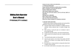
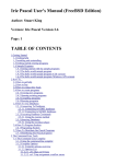
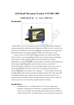
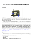
Sliding Gate Operator User's Manual EN V I RO 6 S G e a r -D r i v e n http://www.phoenixgaragedoors.com.au/ ENVIRO 6S SLIDING GATE OPERATOR OUTLINE 1. Products introduction 2 2. Important safety precautions 2 3. Main technical parameters 2 4. Mechanical Installation 3 5. Adjustment 5 6. Wire Connecting 6 7. Electrical and control board 7 8. Porgramming Process 8 9. Maintenance 10 10. Trouble Shooting 11 11. Packing list 11 12. Warranty Registration 11 1 ENVIRO 6S SLIDING GATE OPERATOR 1. Products introduction please read the instructions carefully before proceeding. The operator contains Extra battery, transformer, control board and radio control. In case of power of failure, the operator is powered by a 24Vdc, 1.3Ah, extra battery. Intelligent charging system supplied. MCU is supplied to control the gate operator. Keypad / single button interface. Photo beam safety beam interface. User can select Auto-close feature Soft start & soft stop. Manual key release design for emergency purposes. Gate operator has auto-reverse function, and the reverse power can change by user. 2. Important safety information Carefully read and follow all safety precaution and warnings before attempting to install and use this automatic gate operator. Make sure the Power supply(AC220V) of operator is suitable for the power supply in your area. 3. Main technical parameters Unit Model ENVIRO 6S Power Supply 220VAC Maximum gate weight 220V 300Kg AC Maximum gate width 110V 8mAC Motor 24VDC 100W Output torque Max. 8N m Work duty S2 30min Limit switch Electronical Limit Gate Move speed 13m/min Remote control range 30 meters extra remote control 20 Frequency 100 (2 included) 433.92 MHz Noise 60 dB Working temperature -20 C ~ +50 C Extra Battery 24V 1.3 Ah 2 ENVIRO 6S SLIDING GATE OPERATOR 4. Mechanical Installation The ENVIRO 6S will handle gate weighting up to 300Kg and up to 8m if the proper installation procedures have been followed. The ENVIRO 6S gate operator operates by forcing a drive rack by a drive gear. The entire configuration is shown in the diagram below. The gate operator must be installed on the inside of the gate. Switch Wall Sliding gate Rack Input power Gate operator Fig.1 Gate preparation Be sure the gate is properly installed and slides smoothly before installing the ENVIRO 6S sliding gate operator. The gate must be plumb, level, and move freely. Conduit In order to protect the wires, use PVC conduit for low voltage power cable and control wires. Conduit must be preset into the concrete when it is poured. Wires within the conduit shall be located or protected so that no damage can result from contact with any rough or sharp part. Concrete pad The base unit of the gate operator requires a concrete pad in order to maintain proper stability. The concrete pad should be approximately 400mm x 250mm x 200mm deep in order to provide for adequate weight and structure to insure proper stable installation. Anchors (see Fig.2) You can use anchor bolts, anchors, washers and nuts. These anchors must be set into the concrete when it is poured or you can use wedge anchors to fasten the operator. 3 ENVIRO 6S SLIDING GATE OPERATOR Gate operator Gear Nut Spring washer Plain washer Nut Groundsill Input power Fig.2 Operator base (see Fig.3) After the concrete has hardened, mount the gate operator base to the concrete pad. Verify that the base is properly leveled. Using bolts and washers mount the gate operator to the base and insert the cover. Check the operator and make sure it is lined up with the gate. Fig.3 4 ENVIRO 6S SLIDING GATE OPERATOR Installation of Rack Fix the three nuts (in the same package with rack) on the rack element. Lay the first piece of rack on the gear and weld the first nut on the gate. Move the gate manually, checking if the rack is resting on the gear, and weld the second and third nut. Bring another rack element near to the previous one. Move the gate manually and weld the three nuts as the first rack, thus proceeding until the gate is fully covered. When the rack has been installed, to ensure it meshes correctly with the gear. The space between rack and gear is about 0.5mm. Fig.4 5. Adjustment Sliding gate Rack Gear Fig.5 5 ENVIRO 6S SLIDING GATE OPERATOR Manual operation In case of power failure use manual release key to open or close gate manually, use the release key as follow: Fit the supplied key in the hole. Turn the key clockwise to release the clutch. Open and close the gate manually. After power-restored use the manual release key to tight the clutch by turning the key counterclockwise and resume normal operation. Release Release hole Release key Fig.6 NOTE The gate operator needed reset limit after re-tight the clutch by turning the key counterclockwise if the power failure and released by hand. 6. Wire Connecting Connecting the battery Plug the terminal of Extra battery in the control board. NOTE:If you not use gate operator and power failure, please pull out the extra battery terminal. SOLAR PANEL BLACK TO SOLAR BAT - RED TO SOLAR BAT + Battery Battery Fig.7 6 BLACK TO Charge BAT RED TO Charge BAT + ENVIRO 6S SLIDING GATE OPERATOR Connecting the motor Connect motor wires to M- and M+ of terminal block T1 (BLACK)and T2(RED). Connecting power wire Transformer primary L N PE Power supply AC220V Fig.8 7.Electrical and control board Fig.9 Motor: black wire to T1 and red wire to T2. J1: transformer secondary(AC24V/3.3A) external Push Button(J2,J3,J4): Single Button(OSC and COM) Three Button(K,G,T,and COM), Photo beam(PE and COM) Output DC power: 24 and GND J5: solar panel(10W 27V) and charge Battery. NOTE: Please put through the J5 (Battrey) terminal, if you need use the sliding gate 7 ENVIRO 6S SLIDING GATE OPERATOR operator. 8. Programming Process SET button: Mode set and Confirm function CODE button: Transmitter set and clear function OPEN button: open door CLOSE button: close door OPEN CODE SET CLOSE Fig.10 Adding extra transmitter (learn) 1. Press CODE, a dot is indicated on the LED display. 2. Press the transmitter button which you want to use (button 1, 2, 3, 4), then press the same button again. 3. The dot on the LED display will flash then turn off. 4. ’||’ is indicated on the LED display, then the learning process is finished. Up to 20 transmitters may be used. OPEN CODE SET CLOSE 2 1 OPEN OPEN CODE SET CODE SET CLOSE CLOSE 3 4 Fig.11 Erase transmitter Press and hold CODE until ’C’ flashes on the LED display. This indicates that all the transmitters have been erased completely. OPEN CODE SET CLOSE Fig.12 8 ENVIRO 6S SLIDING GATE OPERATOR Set open and close positions 1. Press and hold SET until number 1 is indicated on the LED display. 2. Press and hold OPEN to set open position(now the door must be OPEN,, if not,please change the motor wire red and black), release the button until the door has reached the desired position. (You also can press CLOSE to move the door close, OPEN and CLOSE can be used to fine adjust the door position.) 3. Press the SET to confirm the open position, now number 2 is indicated on the LED display. 4. Press and hold CLOSE to set close position, release the button until the door has reached the desired position. (You also can press OPEN to move the door open, OPEN and CLOSE can be used to fine adjust the door position.) 5. Press the SET to confirm the close position. 6. The door will do a complete open and close cycle. OPEN OPEN CODE SET CODE SET CLOSE CLOSE OPEN OPEN CODE SET CODE SET CLOSE CODE SET CLOSE OPEN CLOSE Fig.13 Automatic close (0~90 seconds adjustable) 1. Press and hold OPEN until is indicated on the LED display. 2. Press OPEN to increase the auto close time, press CLOSE to decrease time. 3. Set timer to 0 , the automatic close function will disable. 4. Press SET to confirm the setting. 5. Add 10 second per number NOTE: Automatic close function is available only when the door is in fully opened position. OPEN OPEN CODE SET CLOSE Setting obstruction force OPEN CODE SET CLOSE 9 CODE SET CLOSE ENVIRO 6S SLIDING GATE OPERATOR If the door meet an obstruction during closing, it will stop and reverse about 15cm~20cm. 1. Press and hold SET. The LED will display number from ’1’ to ’4’, when the number ’3’ appears on the LED display, release the SET. 2. Press OPEN to increase the obstruction force, the maximum force is level 9. Press CLOSE to decrease force, the minimum force is level 1. 3. Press SET to confirm. Fig.14 Photo beam: Connect the photo beam follow Figure. The photo beam output signal must be N.C. signal. Press and hold close until ’─’ is indicated on the LED display. release the close,’11’will indicated on the LED display. Press open, ’H’ will indicated on the LED display. Press SET to confirm.Then Connect the photo beam follow the Figure.( Note: When not using photo beam, please click the above action and set to "11" status) 24 PE Photo receiver GND Photo transmitter Fig.15 9. Maintenance l Check the door once a month. The door should be carefully checked for balance. The door must be in good working order. l The auto-reverse function should be regularly inspected, and adjusted if necessary. For service, call an experienced serviceman. l We suggest for safety reasons, photocells be used on all gates. l Disconnect from mains supply before replacing bulb. 10 ENVIRO 6S SLIDING GATE OPERATOR Be sure to read the entire manual before attempting to perform any installation or service to the door operator. Our company reserves the right to change the design and specification without prior notification. 10. Troubleshooting Trouble Possible causes The door fails to open and close. LED display does not light. Solutions 1. Power is OFF 1. Make sure that power is ON. 2. Fuse burn 2. Replace fuse. 1. Infrared beam is obstructed. 1. Remove obstructions. The door can open, fails 2.Infrared photocell function is to close. enable, but the photocell has not 2.Make sure the infrared photocell function is disable. been installed. Remote control does not 1. Battery level may be low, work. 2. Transmitter 1. Replace the battery inside the transmitter. 2.Re-program the transmitter. Battery level may be low. Replace battery. The transmitter operating distance is too short. 11. Packing list After receiving the gate operator, you should make an unpack-inspection, in which you should check whether the product was damaged. If you have any problem please contact our dealer. You should find the following items in our standard packing: No. 1 12 . Item Quantity ENVIRO 6S sliding gate operator 1 2 hand transmitter 2 3 Release key 1 4 User s manual 1 Warranty Registration For your operator warranty registration, please visit our website www.phoenixgaragedoors.com.au/warranty-registration/ 11