1
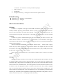
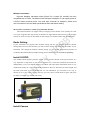
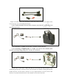
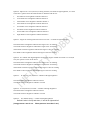
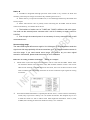
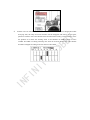
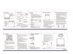
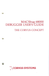
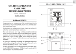
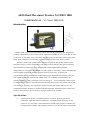
AEO Head Movement Tracker X-GYRO 1000
USER MANUAL(V1.1bata 20091019)
Introduction
X-GYRO 1000 is a two axis head tracking system, based on G sensor technique, designed for
tracking complicated three-dimensional motion like head movement and so on, it can also be used
on the areas of controlling drones and robots, transferring three-dimensional motion signals from
hands, head of human to corresponding movement system on RC model, drone or robot.
The basic version of X-GYRO 1000 is specially designed for RC models with FPV(First
Personal Version), it can be used perfectly with main stream transmitters that gets self defining
trainer channel on market or to be co-operated with wireless high frequency modular
independently. It can transfer the checked movement signals to transmitter, and the transmitter can
send out signals of head movement or position of head( on two axis), so that the real
synchronization can be realized when screen on the goggles displayed video pictures, users can
look around as if he were inside the RC model. Since it is compatible with transmitters on
nowadays market, it is easy and simple to use it and grasp it, its best advantage is that no need
any fixed reference object to check and measure the inflection position of RC model, and no drift
at all when it in stationary state compared with other facilities that need to make use of very
complicated reference facilities or manual controlled transmitter, mechanical arms or other tools
are heavy and not easy to be carried along, it greatly limited users’ freedom.
Specifications:
1.
requirement for power:X-GYRO needs 8V to 12V DC power supply. Some
transmitters, especially those FUTABA ones, can supply power directly by trainer
connector. (ex. T9Z, FF9C). Some transmitters cannot supply power to X-GYRO, for
example 14MZ and 12FG. The simplest solution is to use an extra battery for those RC
transmitters. The connector is already included in package.
2.
Size: 25mmX35mm
3.
Weight:20g
4.
Range for measuring: +-90 degree/second rotational speed movement.
Default Setting:
z Channels: X axis- channel 7 Y axis-channel 8
z Detective range:45 degree
Choice for transmitters
FUTABA:
X-GYRO is compatible with high end FUTABA transmitters (FF-7, FF-8, FF-9, T9Z,
T12MZ, T14MZ) supporting trainer/student function by using 6 pins square trainer connector.
Some of these transmitters can supply power directly to X-GYRO, no need external power, but
some transmitters using need external power for X-GYRO. The external power wire has included
in package.
X-GYRO can generate standard PPM signal and send it through your radio to receiver. (The
default channel: channel 7 and channel 8, its programmable.) Your transmitter need support
trainer function and channels need to be programmable. The system can send standard PPM signal
to those unused channels,
Since the FUTABA transmitters(especially the FF9/9C series), trainer switch is spring
switch, only if you leave it always “on” can realize its function. The simplest way for it is to hold
the switch on with a rubber band. Other high-end transmitters such as (T9Z, T14MZ) have already
put the trainer channel to always “on” channel.
Other notice is the trainer function of some models of Futaba need to reset after you change
model.
Graupner
High-end Graupner transmitters can be used with X-GYRO(MC20, MC24, MX22), and they
are actually support selective trainer channel merging. You can also check the manual of the
transmitter and get the procedure correspondingly, but these expensive transmitters didn’t take the
trainer connector as a standard feature. You need to purchase a trainer connector module to active
the function. Once the appropriate module is installed in the transmitter, the X-GYRO, equipped
with a 3.5mm stereo JACK connector may be used. These connectors don’t supply power, you
need to connect an external power for it. The simplest way is to use a 9V battery, since the current
drawn by the X-GYRO is low enough that a single battery should last a long time, of course, it
will be economical if you use a 7.4V high capacity Li-Po battery.
Multiplex transmitter:
High-end Multiplex transmitter series (Royal Evo, Cockpit SX, mc4000) can also
compatible with X-GYRO. The different with Graupner is Multiplex Tx can supply power to
X-GYRO without external power. You need right connecter for Multiplex, please read
user’s manual to know the detail specifications about transmitter setting.
JR and other transmitters without programmable channel:
Some JR transmitters can support selective merging trainer channel, some of them can’t, but
it is so pity it appears that only the first 4 channels are supported (the JR 9303, 9X is one example
of this). So users can only use X-GYRO on those simple 2-3 channel models with JR transmitter.
Radio Setting:
If your transmitter can program their channel setting and also can program student’s channel
setting while turn on trainer function, you don’t need to change the setting the X-GYRO. If your
transmitter can’t change the student’s channel setting, you can use the programming function of
X-GYRO. More detail about X-GYRO setting, please read the section “X-GYRO Porgramming”.
Install X-GYRO
This module checks angular positions around 2 axis, just like showed on the picture below, It’s
very important to align them to your head’s rotation axes, so that the measured movements are
independently. If it is not aligned properly, the sensor will report false information which is very
troublesome during use. The unit should be mounted so that it is flat when you look straight, and
the cable exits either in front or at the back. To ease installation, you can attach it to a cap, or
directly fix it to your video goggles. That way you won’t have to think about it again, and you’ll
be able it to transfer it to another pilot easily.
Install Camera
For use with the X-GYRO, your camera needs to be mounted on a pan/tilt, and that can be 2 R/C
servos controlled.
Standard R/C servos will get about a 90° total throw, which is enough for the tilt axis. However, it
would be very useful if the pan servo can throw over a wider range. This can be done by hardware
servo modification, but in order to easy the challenge, we have developed the Servo Expansion
module that can double the movement command received from the TX once plugged between the
receiver and the servo. This allows using the maximal throw the servo’s mechanical limits will
accept, usually around 180°. We recommend using it on the Pan axis
Preparing:
The X-GYRO sensor is a plug-and-play device that can be used very easily. There will however be
several settings to be done like for a model’s controls. First, your transmitter’s trainer function
must be activated. Appoint the sensor’s channels (7 and 8 by default, see “Programming” to
change them) to the student, and the rest channels to the trainer.
Using:
The package included additional connecters. (see picture) Twos type Futaba adapter
and one external power connecter.
Plug the X-GYRO cable in your transmitter’s trainer plug, and lay the sensor on a stable surface
so that it doesn’t move at all while powering up.
If your Futaba transmitter has less than 8 channel, such like 4VF or 6EX, you need
use PPM signal mixer.
If your transmitter is Futaba 8 CH or upper, just direct connect and play.
If your transmitter is Futaba T12MZ or T14MZ, you need to use external power
connector (included in box) and 2 cell Li-Po with JST connecter.
Turn the TX on. The sensor’s LED will blink just one second (the fastest response in the
world at the present time). It can be saved as “zero movement” for reference .During this time; the
module stores the “zero movement” reference. It’s very important NOT to move the sensor at that
moment, as any little measurement error will cumulate over time and create drift.
After few seconds, move your X-GYRO. Your camera ptz should be moving
synchronize with X-GYRO. If you leave X-GRRO static in 30 sec but can see ptx moving.
although the system is designed by our excellent engineer, almost no motionless drift for the
system, but it can also generate minor drift by long time and repeated movement, so that head
movement cannot match up the position of the camera, you can simply look straight and press the
button shortly, the system will rememorize central position and correct its output signal instantly
to secure movement synchronism. The processing is so short that you make no influence during
flying.
The temperature change may cause the center moving.
If the center has deviation, just short press the button to re-center X-GYOR
X-GYRO Programming:
The configuration menu is entered at power-up, when power is applied, the LED will blink with
high brightness and it indicates entering menu options, following high brightness blinks comes
with continuous and interval low brightness blinks, it indicates the present menu options, you can
select your desired option in turn from them continuously and periodically by a short button press.
A long press(>2 second) will store it and the next setting then appears, the same setting interface
can be repeated and periodical, if you want to finish the present settings, you can just shut off the
power and then turn on it again.
Entering setting mode:
Please press the re-center button continuously, then connect with the power and wait for 5 seconds,
so you can enter setting mode, the sensor’s LED will blink for reminding the entering setting
mode afterwards.
You can see two signal lights blinking with different brightness.
The times of high brightness blinks indicates serial numbers of menu and the times of continuous
low brightness blinks indicate option numbers on menu
Option 1: Options for X axis (pan axis) working channel---one high brightness blink.
1.
One blink of low brightness indicates Channel 1
2.
Tow blinks of low brightness indicate channel 2
3.
Three blinks of low brightness indicate channel 3
4.
Four blinks of low brightness indicate channel 4
5.
Five blinks of low brightness indicate channel 5
6.
Six blinks of low brightness indicate channel 6
7.
Seven blinks of low brightness indicate channel 7
8.
Eight blinks of low brightness indicate channel 8
Option 2: Options for Y axis (tilt axis) working channel, two blinks of high brightness, it is same
as the above, please select the channels that are different with X axis.
1.
One blink of low brightness indicates Channel 1
2.
Tow blinks of low brightness indicate channel 2
3.
Three blinks of low brightness indicate channel 3
4.
Four blinks of low brightness indicate channel 4
5.
Five blinks of low brightness indicate channel 5
6.
Six blinks of low brightness indicate channel 6
7.
Seven blinks of low brightness indicate channel 7
8.
Eight blinks of low brightness indicate channel 8
Option 3: Angles for tracking head movement on X axis----3 blinks of high brightness
One blink with low brightness indicates the angle of 45° for tracking.
Two blinks with low brightness indicate the angle of 90° for tracking
Three blinks with low brightness indicate the angle of 180° for tracking
Four blinks of low brightness indicate the angle of 360° for tracking
Option 4: It is 4-blink with high brightness for tracking angles of head movement on Y axis(tilt
axis), the options is same as the above.
One blink with low brightness indicates the angle of 45° for tracking.
Two blinks with low brightness indicate the angle of 90° for tracking
Three blinks with low brightness indicate the angle of 180° for tracking
Four blinks of low brightness indicate the angle of 360° for tracking
Option 5:
X axis(pan axis) reversed---5 blinks with high brightness
One blink with low brightness indicates normal
Two blinks with low brightness indicate reversed
Option 6: Y axis(Tilt axis) reversed--- 6 blinks with high brightness
One blink with low brightness indicates normal
Two blinks with low brightness indicate reversed
Option 6:
Go default setting--- 7 blinks with high brightness
Default X axis is for up and down, Y axis is for right and left.
(Long process: over 2 sec.
Short process: less than 1 sec.)
Notice:
1.X-GYRO is integrated with high precision sensor which is very sensitive to shock and
moisture, please keep its storage environment dry and take good care of it.
2.Please don’t try to open the X-GYRO case, or it will damage and destroy the module and
lost free repair.
3.Please take extreme care of polarity when connecting the X-GYRO with the trainer
connector and battery, it will burn the IC device
4.The interface of trainer cord of T14MZ and T12MZ is different with other types.
You need use the external power connecter with 3 cell Li-Po battery to supply power for
X-GYRO.
5.Even though the external power it not necessary for every transmitter, but we still
recommend use it.
Servo moving range
The stand PPM signal define servo angle in 90~120 degree. If the head tracker sends the
signal over this range probably will cause transmitter error. The human head movement is
over this range. If you need extend servo range, you need to buy our servo signal
extension. More detail, please read the manual of servo extension.
Reference for setting of Futaba transmitter (FF-9C for example)
1.
Futaba FF-9 C(and other high-end transmitters) can be used with X-GYRO. Please select
one channelin Trainer menu, and leave it on, shut off other channels. Notice: You can use
either FUNC channel or NORM channel on the menu, leave one of them on and it works
with X-GYRO-1000. But FUNC channnel can let the transmitter input signal for mixing
movement.
2.
Since the FUTABA transmitters(especially the FF9/9C series),trainer switch is momentary
switch, only if you leave it always “on” can realize its function. The simplest way for it is
to hold the switch on with a rubber band. Other high-end transmitters such as (T9Z,
T14MZ) have already put the trainer channel to always “on” Channel.
3.
Another notice on Futaba transmitters should be taken care of: when user changed his model
he flying with, the setup for trainer function will be disappear and need to be set again,
please be careful to active the throttle trainer function before setting. One best way to solve
the problem is to check the working states of all channels on SERVO menu to know
whether X-GYRO is working normally, this work can be done at any time. The channel
should be changed according to the movement of X-GYRO.