1
TM
Argo Navis
User Manual
Edition 10, May 2008, for Argo NavisTM Model 102 & 102B,
Firmware version 2.0.1
Argo Navis™
Argo Navis™ User Manual Edition 10, May 2008, for Argo Navis™ Model 102/102B, Firmware Vers.2.0.1
1
Congratulations
You have purchased one of the most
sophisticated devices for rapidly and
confidently locating celestial objects. The
Argo NavisTM Digital Telescope
Computer (DTC) brings not only accurate
positioning information to your telescope
but also provides an enormous detailed
database of tens of thousands of objects.
Stars, galaxies, galaxy clusters,
globular clusters, open clusters, planetary
nebulae, nebulae, planets, asteroids,
comets, earth-orbiting satellites and more.
Magnitudes, surface brightness, object
sizes, common names, stellar
classifications, stellar luminosity classes,
double star separations, variable star
periods, Hubble galaxy morphologies,
constellation, detailed parameters of
planets, comets, asteroids, satellites and
a wealth of other information are available
at your fingertips with a simple spin of the
dial.
A large range of mounts can
accommodate the Argo NavisTM
including Dobsonians, Forks, German
Equatorials and Equatorial Tables.
Handheld and powered by AA
batteries, or an optional external DC
source, Argo NavisTM operates
completely standalone.
After fitting a pair of optical encoders to
your mount, using the Argo NavisTM is
simple. Perform a quick star alignment
and off you go. There is no need to level
or accurately polar align your mount. It's
fast and easy.
Using the innovative, Intelligent Editing
SystemTM, objects from the in-built
catalogs can be accessed quickly and
easily by name. You can select a
particular object and then Argo NavisTM
can provide you with “guiding” information
that will allow you to zero-in on it by
simply manually turning the scope.
Alternatively, objects of interest can be
reported to you on the display in real-time
as you move your scope. Argo NavisTM
has a powerful 32-bit CPU at its heart that
will easily allow you to continuously track
satellites. The sophisticated software
even accounts for precession, nutation
and atmospheric refraction. A battery
backed real-time clock provides local
time, UTC time, Julian date and sidereal
time.
The versatile and powerful tour mode
allows you to tailor your searches of the
sky so that you may seek to find the types
of objects that interest you the most, be
they easy or highly challenging.
Though designed for standalone use,
Argo NavisTM can also be interfaced to
your PC or laptop, which brings about a
wealth of additional features. It can
operate with many of the popular sky
charting packages to provide you with a
tracking cursor display. Using the supplied
ArgonautTM utility, it even lets you store
into its FLASH memory over a thousand
of your own user-defined objects including
magnitudes and descriptions. You can
erase them and store new ones as often
as you like.
This User Manual shows how the
Argo NavisTM Digital Telescope
Computer can make your observing
sessions more enjoyable and rewarding.
Argo Navis™
Argo Navis™ User Manual Edition 10, May 2008, for Argo Navis™ Model 102/102B, Firmware Vers.2.0.1
2
Contents
This manual ......................................................................................................................... 6
The Argo Navis interfaces ............................................................................................... 7
The user interface ........................................................................................................ 7
The encoder interface .................................................................................................. 8
The serial interface....................................................................................................... 9
Initial setup of the Argo Navis ........................................................................................ 11
Power sources ........................................................................................................... 11
Setting the initial mount type ...................................................................................... 13
Setting encoder steps (resolution).............................................................................. 13
Setting altitude steps.................................................................................................. 14
Setting azimuth steps................................................................................................. 14
Testing encoder communication................................................................................. 15
Determining encoder direction senses ....................................................................... 16
Setting the final mount type........................................................................................ 17
Setting the local time zone, date and time.................................................................. 19
Setting the location..................................................................................................... 21
Setting refraction modelling........................................................................................ 23
Alignment procedures ........................................................................................................ 24
Purpose of alignment ................................................................................................. 24
Fork Exact Align and German Equatorial Exact Align Mounts .................................... 24
Alt/Az Dobsonian Mounts including on Equatorial Tables........................................... 25
Fork Rough Align Mounts........................................................................................... 27
GEM Rough Align ...................................................................................................... 28
An introductory run ............................................................................................................ 31
Operating modes ............................................................................................................... 36
MODE ALIGN ................................................................................................................ 37
MODE ALIGN STAR...................................................................................................... 39
MODE AZ ALT ............................................................................................................... 43
MODE CATALOG .......................................................................................................... 44
MODE ENCODER ......................................................................................................... 50
MODE EQ TABLE.......................................................................................................... 54
MODE FIX ALT REF...................................................................................................... 57
MODE IDENTIFY........................................................................................................... 61
MODE RA DEC.............................................................................................................. 68
MODE SETUP ............................................................................................................... 70
MODE SIDEREAL ......................................................................................................... 72
MODE STATUS ............................................................................................................. 73
MODE TIME .................................................................................................................. 74
MODE TIMER ................................................................................................................ 75
MODE TOUR................................................................................................................. 76
SETUP ALIGN PICK...................................................................................................... 83
Argo Navis™
Argo Navis™ User Manual Edition 10, May 2008, for Argo Navis™ Model 102/102B, Firmware Vers.2.0.1
3
SETUP ALT REF ........................................................................................................... 85
SETUP ALT STEPS....................................................................................................... 87
SETUP ATLAS .............................................................................................................. 88
SETUP AZ STEPS......................................................................................................... 90
SETUP BRIGHTNESS................................................................................................... 91
SETUP CONTRAST ...................................................................................................... 92
SETUP DATE/TIME....................................................................................................... 93
SETUP DEBUG ............................................................................................................. 96
SETUP DEFAULTS ....................................................................................................... 97
SETUP ENC TIMING ..................................................................................................... 98
SETUP EQ TABLE ...................................................................................................... 101
SETUP GOTO ............................................................................................................. 103
SETUP GUIDE MODE ................................................................................................. 106
SETUP LCD HEATER ................................................................................................. 108
SETUP LOAD CAT ...................................................................................................... 109
SETUP LOCATION...................................................................................................... 111
SETUP MOUNT........................................................................................................... 114
SETUP MNT ERRORS ................................................................................................ 115
SETUP REFRACTION................................................................................................. 143
SETUP SCRATCH....................................................................................................... 145
SETUP SCROLL.......................................................................................................... 147
SETUP SERIAL ........................................................................................................... 148
Argonaut software utility .............................................................................................. 152
ArgonautTM introduction ....................................................................................... 152
What does ArgonautTM do? .................................................................................. 152
What else do I need besides ArgonautTM? ........................................................... 152
Installing ArgonautTM ............................................................................................ 153
Launching ArgonautTM ......................................................................................... 157
Establishing communication..................................................................................... 157
Where to obtain Asteroid, Comet or Satellite Orbital Element Files .......................... 160
How to create your own User catalog files................................................................ 161
Transferring catalog files .......................................................................................... 163
Updating catalog entries........................................................................................... 166
Deleting loadable catalogs ....................................................................................... 166
Querying loadable catalog free memory................................................................... 167
Transferring firmware files........................................................................................ 168
LinuxTM operating system file transfer utilities............................................................ 170
Mac OS XTM operating system file transfer utility ....................................................... 171
Programmer’s reference .................................................................................................. 172
asteroid........................................................................................................................ 173
comet........................................................................................................................... 174
date.............................................................................................................................. 175
enc............................................................................................................................... 176
Argo Navis™
Argo Navis™ User Manual Edition 10, May 2008, for Argo Navis™ Model 102/102B, Firmware Vers.2.0.1
4
encctl ........................................................................................................................... 177
event............................................................................................................................ 178
fp ................................................................................................................................. 179
meade.......................................................................................................................... 180
navis ............................................................................................................................ 182
pbt................................................................................................................................ 183
rad ............................................................................................................................... 184
samples ....................................................................................................................... 185
satellite ........................................................................................................................ 186
servocat ....................................................................................................................... 187
setups .......................................................................................................................... 188
sitech ........................................................................................................................... 189
skycomm...................................................................................................................... 190
tangent......................................................................................................................... 191
therm ........................................................................................................................... 192
uptime.......................................................................................................................... 193
user.............................................................................................................................. 194
Appendix A—Catalogs..................................................................................................... 195
Appendix B—Technical specifications ............................................................................. 197
Appendix C—Port pin descriptions................................................................................... 199
Appendix D—Factors that affect pointing accuracy.......................................................... 200
Appendix E—Factors that affect encoder direction senses .............................................. 201
Appendix F—How to replace the lithium coin cell battery................................................. 202
Appendix G—Troubleshooting guide ............................................................................... 205
Appendix H—How Argo Navis orders its symbols ....................................................... 208
Appendix I—World time zones......................................................................................... 209
Appendix J—Warranty ..................................................................................................... 218
Appendix K—Conformance.............................................................................................. 220
Appendix L—Glossary ..................................................................................................... 223
Index................................................................................................................................ 226
Argo Navis™
Argo Navis™ User Manual Edition 10, May 2008, for Argo Navis™ Model 102/102B, Firmware Vers.2.0.1
5
This manual
This section describes the content of
the manual and how to use it.
Introduction
This manual is divided into 9 main
sections:
• How to use this manual
• The Argo NavisTM interfaces
• Initial setup of the Argo NavisTM;
• Alignment procedures
• An introductory run
• Operating modes
• The ArgonautTM software utility
• Programmer’s reference
• Appendices
Content of the manual
The Argo NavisTM interfaces
describes the front panel of the Argo
NavisTM, including the DIAL, the EXIT
and ENTER buttons, and the ports on top
of the Argo NavisTM.
Initial setup of the Argo NavisTM
describes the once-only requirements for
setting-up the Argo NavisTM to suit your
mount-type and your individual
requirements.
Alignment procedures describes how
to align Argo NavisTM rapidly for use
each night.
An introductory run describes how to
use the Argo NavisTM to find objects
once the initial setup has been performed
and Argo NavisTM have been aligned.
Operating modes describes the
purpose of each mode in the Argo
NavisTM firmware and how to use them,
and provides examples.
The ArgonautTM software utility
describes the use of the supplied
ArgonautTM program, which runs on a
PC. This software allows you to download
to your unit asteroid, comet and satellite
orbital elements as well your own user
catalogs. You also use ArgonautTM to
upgrade your Argo NavisTM firmware
and in-built catalogs.
The Programmer’s reference is
designed for software developers who
would like to write applications that can
interface with Argo NavisTM.
The Appendices contain additional
information on the Argo NavisTM.
How to use this manual
Don’t be daunted by the size of this
manual. If you just want to get going, it is
suggested that you read:
• Initial setup of the Argo NavisTM;
• Alignment procedures and
• An introductory run
If you want to know all of the features
of the Argo NavisTM, it is suggested that
you read all of the chapters sequentially.
Don’t forget there is a glossary and an
index if you need it, and the operating
modes are all fully described. If you are
reading this manual online as a PDF file,
be sure to make use of the hyperlinks and
the Acrobat Bookmarks navigation menu
to help find your way around. Watch for
updates of this manual at the Wildcard
Innovations web site.
Argo Navis™
Argo Navis™ User Manual Edition 10, May 2008, for Argo Navis™ Model 102/102B, Firmware Vers.2.0.1
6
The Argo Navis interfaces
This section describes the various
interfaces of the Argo NavisTM.
Types of interface
The Argo NavisTM has 3 interfaces:
• the user interface;
• the encoder interface;
• the serial interface.
Each type of interface is described
below.
The user interface
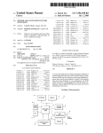
The user interface is the front panel
and consists of five elements as shown in
Figure 1.
• the ON/OFF switch;
• the liquid crystal display (LCD));
• the DIAL;
• the ENTER button;
• the EXIT button.
The ON/OFF switch is located at the
top, left-hand of the front panel - ON is
marked with “I”; OFF is marked with “O”.
The LCD is the horizontal window
located near the top of the front panel.
When the power is off the LCD will appear
to be a blue colour. When the power is on
the display will appear to be a red colour.
Argo NavisTM uses a red display
because this colour is less likely to impact
upon your night vision, which is important
when you want to view faint celestial
objects. The brightness of the display can
also be altered to suit your current viewing
conditions (see page SETUP BRIGHTNESS).
Figure 1 (Argo
Argo NavisTM Model 102B shown)
Argo Navis™
Argo Navis™ User Manual Edition 10, May 2008, for Argo Navis™ Model 102/102B, Firmware Vers.2.0.1
7
“Firmware” is the term used to describe
the software in an electronic appliance.
The Argo NavisTM firmware is organized
as a set of menus which you can navigate
by using the DIAL and the ENTER and
EXIT buttons.
The DIAL is located in the centre of the
front panel. It is used to scroll through the
menus, to alter an item within a menu and
to manually scroll long text messages.
The DIAL has what are known as “detent
clicks” (see Glossary). Sometimes you will
need to move the DIAL one detent “click”
at a time.
The ENTER button is located on the
right-hand side of the front panel. It is
used to enter a particular menu you have
selected with the DIAL and to select a
particular item within a menu.
The EXIT button is located on the lefthand side of the front panel. It is used to
exit from menu selections.
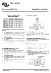
The encoder interface
The encoder interface is the receptacle
found on top of the unit and marked by
the label “ENCODERS”. See Figure 2. If
you study your encoder cable, you will
find one end has an 8-way RJ-45 plug
from which two 4-way cables split. Insert
this plug into the encoder interface
receptacle.
If you have an encoder cable assembly
supplied by Wildcard Innovations, the 4way cable that has a white sleeve near
the encoder end will go to the Altitude axis
encoder. The other 4-way cable will go to
the Azimuth axis encoder.
The Argo NavisTM Digital Telescope
Computer (DTC) encoder interface was
designed to be pin and electrically
compatible with that used on the older JMI
NGC-MAXTM, Celestron Advanced
AstromasterTM, Lumicom Sky VectorTM,
SkyComm Engineering Sky
CommanderTM and similar Digital Setting
Circle (DSC) units. Therefore, if you are
upgrading to an Argo NavisTM from one
of these older units, you can retain your
existing encoders and cable. Note,
however, that the Argo NavisTM
supports a higher encoder sampling rate
Figure 2 (Argo
Argo NavisTM Model 102B shown)
Argo Navis™
Argo Navis™ User Manual Edition 10, May 2008, for Argo Navis™ Model 102/102B, Firmware Vers.2.0.1
8
than these older units and therefore will
reliably support higher resolution
encoders. Though Argo NavisTM will
work with lower resolution encoders,
Wildcard Innovations recommends that
you consider upgrading to 10,000 step
encoders if you would like to achieve
potentially finer pointing accuracy.
The serial interface
Argo NavisTM has two RS-232 serial
ports on top of the unit marked SERIAL1
and SERIAL2. See Figure 2. Argo
NavisTM can be used completely
standalone. However, it is also possible to
interface it to a PC or MacintoshTM
computer assuming your PC/Mac has an
RS-232 serial port or a USB port.
If you use an RS-232 serial port
external modem with your PC, it is
possible to unplug temporarily the modem
and to plug in the optional Argo
NavisTM serial port cable (Wildcard
Innovations Part No. pn-ser-cbl).
If your PC/Mac does not have a RS232 serial port but is equipped with a USB
port, Wildcard Innovations have available
a USB to RS-232 Serial Port Adaptor
(Wildcard Innovations Part No. pn-usb)
which works in conjunction with the
optional RS-232 serial cable (pn-ser-cbl).
By communicating with your PC, you
can perform the following tasks:
• Download firmware & in-built
catalog upgrades to the unit. See
the page on Transferring firmware
files for details.
• Download asteroid, comet and
satellite orbital elements. See the
page on Where to obtain Asteroid,
•
•
Comet or Satellite Orbital Element
Files for details.
Download your own user objects.
See the page on How to create
your own User catalog files for
details.
Communicate with a sky-mapping
program such as Star-Atlas
PROTM, The SkyTM, SkyMap ProTM
or XephemTM (and many more) to
have a “tracking cursor” display.
See the SETUP SERIAL page for
details.
The two serial ports operate completely
independently. Their Baud rates
(communications speeds) can be set from
the Argo NavisTM front panel. See the
SETUP SERIAL page.
For all operations, except downloading
new firmware, either serial port can be
used. For downloading firmware,
SERIAL1 is special and is the only port
that can be used for this purpose.
WARNING: The pin assignment on the
Argo
Argo NavisTM serial ports is not
compatible with those of the SkyComm
Engineering Sky CommanderTM.
However, they are compatible with
those on the JMI NGC-MAXTM,
Celestron Advanced AstromasterTM,
Lumicom Sky VectorTM and similar
Digital Setting Circle (DSC) units. (See
Port pin descriptions). To avoid
possible damage to your Argo
NavisTM or PC, we recommend you
use only a genuine Argo NavisTM
optional serial interface cable
(Wildcard Innovations Part No. pn-sercbl).
Argo Navis™
Argo Navis™ User Manual Edition 10, May 2008, for Argo Navis™ Model 102/102B, Firmware Vers.2.0.1
9
WARNING: When interfacing your
Argo NavisTM to a PC, you should be
aware of the possibility of electrostatic
discharge that could result in damage
to your Argo NavisTM, PC and
associated peripherals. Be sure to
ground yourself adequately prior to
interfacing any two pieces of
equipment. Be particularly careful in
static prone environments, especially
in low humidity conditions or while
walking on carpets. Wildcard
Innovations bears no liability for loss
or damage caused to your equipment
from static discharge.
WARNING: It is your responsibility to
ensure that any cables connected to
your Argo NavisTM do not pose a
hazard to yourself and others. Ensure
that it is not possible for yourself or
others to trip over your cabling. You
should be aware that cabling could be
a hazard to persons especially at nighttime and when outdoors. Wildcard
Innovations bears no liability for loss,
damage or injury caused by persons
tripping over your cabling.
Argo Navis™
Argo Navis™ User Manual Edition 10, May 2008, for Argo Navis™ Model 102/102B, Firmware Vers.2.0.1
10
Initial setup of the Argo Navis
This section describes the
once-only requirements for
setting-up the Argo NavisTM
to suit your scope and your
individual requirements. This
includes:
• setting up the power
sources;
• setting your initial mount
type;
• setting your encoder
resolution;
• setting your encoder
senses;
• setting your final mount
type;
• setting the local time zone, date
and time;
• setting your location;
• enabling refraction modelling;
Figure 3 (Argo
Argo NavisTM Model 102B shown)
hatch thumbscrew on the battery housing
(the raised section at the top of the back)
of the Argo NavisTM. Gently slide the
battery cover slightly toward the top of the
unit by about 1cm and then lift it off.
Power sources
There are two types of power source:
• internal battery power; and,
• external battery power.
Internal Battery Power
4 “AA”, 1.5V batteries provide the
internal battery power. These should be
alkaline, lithium or rechargeable NiMH
batteries. Since NiMH batteries have
reduced capacity below 20C (68F), their
use is not recommended in cool or cold
climates. Do not use NiCd or regular/
heavy-duty zinc-oxide batteries.
To install batteries, refer to Figure 3.
Using a coin, remove & retain the battery
To place the batteries in, refer to
Figure 4. Be sure to observe the polarity
indicators inside the battery housing (+ on
the battery should be placed at the same
end as the + on the markings inside the
battery housing). Replace the battery
hatch cover and thumbscrew.
• Ensure batteries are removed from
the Argo NavisTM if it is to be stored
or not used for prolonged periods in
case of battery leakage.
• Do not charge rechargeable batteries
whilst in battery housing.
Argo Navis™
Argo Navis™ User Manual Edition 10, May 2008, for Argo Navis™ Model 102/102B, Firmware Vers.2.0.1
11
External battery power
The optional external DC power cable
allows you the convenience to power the
Argo NavisTM from an external battery
source such as a 12V car battery. The
external power receptacle is found on
the top of the unit and is marked DC IN.
The external battery voltage should be in
the range of 8V to 16V DC. An incorrect
power voltage source or polarity could
cause damage to your unit and void your
warranty. Use only the optional external
DC power cable supplied by Wildcard
Innovations (Part No. pn-pwr-cbl) for
supplying external power to your unit.
Though Argo NavisTM provides in-built
reverse polarity and short circuit
protection, the optional cable contains a
350mA fuse for additional safety.
Figure 4 (Argo
Argo NavisTM Model 102B shown)
•
Do not connect any other form of
power supply to battery terminals.
Fresh alkaline batteries with the display
fully dimmed can provide from 12 to 40
hours usage of the unit depending on
several additional factors including what
type of encoders are installed.
WARNING: Never use a cable with an
incorrect fuse (we recommend
315mA) and never bypass the fuse
protection. Observe all safety
procedures when working with
external batteries. Many contain
dangerous acids that can be spilt and
some batteries are capable of
delivering very large currents that can
destroy equipment or cause a fire if
they are short-circuited.
WARNING: Be careful not to trip or
allow others to trip over the external
power cable or any other cables from
your unit.
Argo Navis™
Argo Navis™ User Manual Edition 10, May 2008, for Argo Navis™ Model 102/102B, Firmware Vers.2.0.1
12
Setting the initial mount type
Argo NavisTM requires you to specify
what style of mount your telescope is on.
However, for the purpose of this
once-only initial setup procedure, you
will be asked to set your mount type to
the FORK EXACT ALIGN setting,
irrespective of what type of mount you
really have.
Later, you will be asked to set the
mount type to match the type of mount
you are using.
Power the unit on. Turn the DIAL
clockwise until you see MODE SETUP
Press ENTER. Now turn the DIAL
clockwise until you see SETUP MOUNT
Notice how Argo NavisTM orders its
various menus alphabetically so you can
find a particular one logically and quickly.
Now press ENTER. The display might
then show ALTAZ/DOBSONIAN
where the whole line will be flashing. Spin
the DIAL until the display shows –
FORK EXACT ALIGN
Then press EXIT or ENTER. Argo
NavisTM will briefly display the words
SAVING ….
while it saves your settings into its
memory (EEROM device) and then
display the message –
SETUP MOUNT
Setting encoder steps
(resolution)
Before you can perform an alignment,
you need to set up in Argo NavisTM the
resolution and “direction senses” of your
altitude and azimuth encoders.
Encoder operation background
Most optical encoders will have a
printed label specifying either their part
number or their resolution. For example, if
you have an encoder marked with the part
number S2-2500, this is a 10,000-step
encoder (10,000 is 4 times 2500 - this
style of encoder is technically known as a
Quadrature Encoder).
When an encoder rotates, it transmits
electrical pulses or ‘steps’. A 10,000-step
encoder will produce 10,000 steps when it
is rotated 360°. Therefore, one ‘step’ on
such an encoder corresponds to an angle
of rotation of about 2.16 arc minutes.
Encoders can be geared to produce a
higher or lower number of ‘steps’ when
the telescope mount bearing they are
attached to rotates through 360°.
In any case, you need to establish how
many steps your encoders produce when
the bearing they are attached to is rotated
through 360°. In many cases, bearings,
particularly altitude (declination) bearings,
may be incapable of being rotated through
a full 360°. Nonetheless, you will still need
to establish how many steps the encoder
Argo Navis™
Argo Navis™ User Manual Edition 10, May 2008, for Argo Navis™ Model 102/102B, Firmware Vers.2.0.1
13
would produce if the bearing could be
rotated through a full 360°.
If the shaft of your encoder is attached
directly to the axis of rotation of the
bearing and is not geared, then the
number of steps for that particular
encoder is simply its rated number of
steps.
back and change the encoder ‘direction
sense’ (the ‘+’ sign or ‘-’ sign) depending
upon your circumstances.
Setting altitude steps
Press ENTER again and the display might
show something like this -
Having established how many steps
each encoder is, spin the DIAL within the
SETUP menu-level until you see SETUP ALT STEPS
Press ENTER and the display might show
something like this ALT=+0010000
where the ‘+’ sign will be flashing. Leave
the sign as a ‘+‘ for now and press
ENTER and edit the fields as need be by
using the DIAL to change a value and
ENTER to advance to the next field.
When the correct number of steps is
displayed, press either ENTER or EXIT
and if the value has changed from what it
originally was, Argo NavisTM will briefly
display the words SAVING ….
while it saves your settings into its
memory (EEROM device) and then
display the message –
SETUP ALT STEPS
Setting azimuth steps
Using the DIAL, go to SETUP AZ STEPS
AZ=+0010000
where the ‘+’ sign will be flashing. Leave
the sign as a ‘+‘ for now and press
ENTER and edit the fields as need be by
using the DIAL to change a value and
ENTER to advance to the next field.
When the correct number of steps is
displayed, press either ENTER or EXIT
and if the value has changed from what it
originally was, Argo NavisTM will briefly
display the words SAVING ….
while it saves your settings into its
memory (EEROM device) and then
display the message –
SETUP AZ STEPS
You have now set your azimuth encoder
step setting. However, as will be
explained later, you may need to come
back and change the encoder ‘direction
sense’ (the ‘+’ sign or ‘-’ sign) depending
upon your circumstances.
You have now set your altitude encoder
step setting. However, as will be
explained later, you may need to come
Argo Navis™
Argo Navis™ User Manual Edition 10, May 2008, for Argo Navis™ Model 102/102B, Firmware Vers.2.0.1
14
Testing encoder communication
Power Argo NavisTM off. Make sure
that your encoders are installed on your
mount and that your encoder cable is
connected both to them and into the
ENCODERS port of the Argo NavisTM.
(See Figure 2.)
Power Argo NavisTM on and use the
DIAL to go to MODE ENCODER
Press ENTER. The display should show
something like this –
AZ/ALT ENC ANGLE
000.00° +000.00°
The display is showing the angle of the
azimuth encoder on the bottom left of the
display and that of the altitude encoder on
the bottom right.
Move the scope in azimuth (Right
Ascension). Make sure that the AZ angle
on the display changes. Now move the
scope in altitude (Declination). Make sure
that the ALT angle changes. If the ALT
reading changes when you move the
scope in azimuth and vice versa, you
have the encoder cables swapped
around. On most encoder cables supplied
by Wildcard Innovations, the cable that
has the white sleeve near its encoder end
should go to the altitude encoder.
If neither or only one angle changes on
the display, check that the connections to
the encoders are correct, in particular
making sure that the plug that connects to
the encoder pin header is inserted the
right way up. On encoders and cables
supplied by Wildcard Innovations, the
correct orientation can be ascertained by
matching the small circular sticker on the
plug with the same type of sticker on top
of the encoder (the side opposite that
from which the shaft protrudes). Also,
ensure that any set-screw holding the
encoder shaft in place is firm and is not
allowing the encoder shaft to slip. Finally,
check the batteries in your Argo
NavisTM and replace them if necessary.
If you are performing the above test
without having installed the encoders on
your mount and you are simply turning the
encoder shafts with your fingers, you may
see one of the following messages on the
display –
•
•
•
AZ ENCODER ERROR
ALT ENCODER ERR
BOTH ENCODER ERR
This simply means that you have turned
the encoders too quickly and have
exceeded their sampling rate, thus
missing counts. Argo NavisTM typically
samples the encoders at a very high rate
(much higher than older Digital Setting
Circle, or ‘DSC’, units) and when the
encoders are installed on your mount, you
should not see these errors during normal
operation. If the encoders are installed on
your mount and you do see these errors,
check the batteries in Argo NavisTM
and the connections on your encoders.
Otherwise see the Troubleshooting guide.
Once you have established that your
Argo NavisTM can reliably
communicate with your encoders, you are
ready to proceed.
Argo Navis™
Argo Navis™ User Manual Edition 10, May 2008, for Argo Navis™ Model 102/102B, Firmware Vers.2.0.1
15
Determining encoder direction
senses
When you were initially setting your
encoder resolution with SETUP ALT STEPS
and SETUP AZ STEPS, you were asked to
ignore the flashing ‘+’ sign. Using the
DIAL, the sign can be made to be either a
‘+’ or a ‘-’. It determines the way that
Argo NavisTM interprets the ‘direction
sense’ of the applicable encoder.
Setting the correct direction senses of
your encoders is very important. Many
factors influence the setting of encoder
direction senses. For example, in the case
of an altitude encoder, whether it is
mounted on the left or right-hand side of
the mount and whether it has been
geared an even or odd number of times
are just two of the factors. The section
named Factors affecting encoder direction
sense details these. For this reason,
determining the correct direction senses
of your encoders may not be simply
intuitive. Fortunately, you can perform a
test with your scope that will tell you what
the correct senses are. Once you have
patiently worked through the test and
have determined the correct settings for
the encoders on your mount, you should
never need to change them again.
To determine the direction senses of
your encoders, follow these instructions.
Power off your Argo NavisTM, and
then power it back on. After it initializes,
you should see –
If your scope is on a Fork Mount,
roughly polar align it. Orient the tube so
that it is the “way-up” you normally
observe, thus –
Figure 5
MODE ALIGN STAR
then press ENTER. The display should
show something like -
If your scope is on a German
Equatorial Mount (GEM), roughly polar
align it. If you are in the Northern
Hemisphere, place the tube on the West
side of the mount. If you are in the
Southern Hemisphere, place the tube on
the East side of the mount.
If your scope is on an Alt/Az Mount,
such as a Dobsonian, just continue
reading. If your Alt/Az mount is mounted
on top of an equatorial table, accurately
polar align the table, move the table to the
start position and switch it off for now.
ALIGN ACHERNAR
Argo Navis™
Argo Navis™ User Manual Edition 10, May 2008, for Argo Navis™ Model 102/102B, Firmware Vers.2.0.1
16
Look up at the sky and pick a familiar
bright star not far from the Celestial
Equator (the imaginary line in the sky
where Declination = 0°.) Spin the DIAL
and look for that star’s name. There are
35 to choose from. The MODE ALIGN STAR
reference page lists the alignment stars. If
you cannot find the star you have chosen
in the list, pick another that is in the list
that is not too far from the Celestial
Equator. For example, say you have
chosen Sirius. Spin the DIAL until you
see ALIGN SIRIUS
Centre Sirius in the eyepiece, then press
ENTER. The display will briefly show
something like this –
ALIGN SIRIUS
WARP= +0.00
Now press EXIT and spin the DIAL until
the display shows –
MODE RA DEC
then press ENTER. The display should
show the approximate Right Ascension
and Declination of the last star you
aligned on. In the example of Sirius, the
display might show something like this 06:45.3 -16°43’
CANIS MAJOR
While watching the RA reading on the
display, rotate the scope slowly in an
Easterly direction. The RA value should
increase. If instead it decreases, take note
of that fact and continue for now.
While watching the Dec reading on the
display, rotate the scope slowly in a
Northerly direction. The Dec value should
increase (a negative Dec value that
becomes more and more negative is in
fact decreasing). If the Dec value is
decreasing, take note of that fact and
continue.
If the Right Ascension and Declination
directions were consistent with the above
procedure, you do not need to alter the
SETUP ALT STEPS or SETUP AZ STEPS
direction senses.
If the Right Ascension reading
decreased as the scope was moved
towards the East, then go back to SETUP
AZ STEPS and change the direction sense
sign.
If the Declination reading decreased as
the scope was moved towards the North,
then go back to SETUP ALT STEPS and
change the direction sense sign.
If you changed either or both signs,
power the unit off and then on and repeat
the procedure to verify that the new
encoder direction senses are correct.
Setting the final mount type
During the initial once-only setup
procedure, you were asked to set the
mount type to FORK EXACT ALIGN. You will
now need to set your mount type to match
your actual mount. If you have a Fork
mount that is exactly polar aligned, you
obviously do not need to change the
setting.
Otherwise, power the unit off, then on.
Turn the DIAL clockwise until you see MODE SETUP
Argo Navis™
Argo Navis™ User Manual Edition 10, May 2008, for Argo Navis™ Model 102/102B, Firmware Vers.2.0.1
17
Press ENTER. Now turn the DIAL
clockwise until you see SETUP MOUNT
while it saves your settings into its
memory (EEROM device) and then
display the message –
SETUP MOUNT
Now press ENTER. The display should
show FORK EXACT ALIGN
where the whole line will be flashing. Spin
the DIAL and select your mount type. The
various mount types are tabled below.
Once you have selected your mount type,
press either EXIT or ENTER. Argo
NavisTM will briefly display the words
SAVING ….
Menu selection
When to use
Number of alignment
stars required
ALTAZ/DOBSONIAN
For altitude/azimuth mounts such as
Dobsonians (but not on equatorial
tables);
For altitude/azimuth mounts
mounted on top of an accurately
polar aligned equatorial table
For any accurately aligned equatorial
mount, such as a fork mount, but not
a German equatorial or an equatorial
table.
For any roughly aligned equatorial
mount, such as a fork mount, but not
a German equatorial or an equatorial
table.
For an accurately polar aligned
German equatorial.
For a roughly aligned German
equatorial.
FIX ALT REF step
EQ TABLE EXACT
FORK EXACT ALIGNED
FORK ROUGH ALIGN
GEM EXACT ALIGN
GEM ROUGH ALIGN
plus 2
alignment stars
FIX ALT REF step
plus 2
alignment stars
One alignment star
FIX ALT REF step
plus 2
alignment stars
One alignment star
step plus 2
alignment stars
FIX ALT REF
Argo Navis™
Argo Navis™ User Manual Edition 10, May 2008, for Argo Navis™ Model 102/102B, Firmware Vers.2.0.1
18
Setting the local time zone, date
and time
Argo NavisTM contains an in-built
battery-backed time of day clock. An
internal lithium coin cell battery powers
the clock even when the power is
switched off or the main batteries are
removed.
Though Argo NavisTM does not
require you to set the time or your location
to operate, doing so provides the following
additional features and benefits:
• The local time and date, the UTC
(Greenwich) time and date and the
current Julian date (see Glossary)
will be available to you from the
MODE TIME menu;
• The Local Apparent Sidereal Time
(LAST) will be available to you in
MODE SIDEREAL if you have also
specified your location;
• The topocentric azimuth and
altitude (see Glossary) will be
available to you in MODE AZ ALT
assuming you have also specified
your location and have performed
a valid star alignment;
• Correction for atmospheric
refraction (see Glossary) will be
made while you point your scope
assuming you have also specified
your location and assuming you
have turned refraction correction
ON in the SETUP REFRACTION submenu.
• Objects will be precessed and
nutated (see Glossary) from their
internally stored J2000.0 epoch
positions to their actual position at
the time you observe them.
•
The positions of planets can be
accurately determined.
• The positions of asteroids and
comets can be computed from
their orbital elements.
• The position of earth orbiting
satellites can be computed
assuming you have also specified
your location.
For these reasons it is worthwhile
setting your local time zone, date and
time. Since Argo NavisTM retains the
time even when it is powered off, you only
need do it once and then possibly
occasionally to correct for normal clock
drift.
To set the local time zone, date and
time, perform the following. Power the unit
on. Turn the DIAL clockwise until you see
MODE SETUP
Press ENTER. Now turn the DIAL
clockwise until you see
SETUP DATE/TIME
Notice how Argo NavisTM orders its
various menus alphabetically so you can
find a particular one logically and quickly.
Press ENTER. Argo NavisTM will display
something like
TIMEZONE=+00:00
Where the ‘+’ (or possibly ‘-‘) sign will be
flashing.
To understand the concept of time
zone, it is important to know that Argo
NavisTM always internally keeps track of
Argo Navis™
Argo Navis™ User Manual Edition 10, May 2008, for Argo Navis™ Model 102/102B, Firmware Vers.2.0.1
19
time in terms of Universal Co-ordinated
Time (UTC), which was previously
referred to as Greenwich Mean Time
(GMT). The time zone is the number of
hours that your local time differs from
UTC. For example, in New York when
Daylight Savings Time (Summer time) is
not in effect, the time zone setting is
-05:00 hours. When Daylight Savings
(summer time) is in effect, the time zone
is –4:00. In Sydney, when Daylight
Savings time is not in effect, the time zone
setting is +10:00 hours and when Daylight
Savings is in effect +11:00. In New Delhi
the time zone is +05:30.
Use the World timezones section of
this manual to determine your local time
zone. If you are in a time zone that is west
of Greenwich, you will set the sign to a ‘-‘.
If you are in a time zone that is east of
Greenwich, you will set the sign to a ‘+’.
By turning the DIAL you can change
the sign alternately between a ‘+’ and a ‘-‘.
When you have selected the correct sign,
hit ENTER, which advances the flashing
‘cursor’ to the first numeric field. You can
change the value in that field by turning
the DIAL. When you have selected the
correct value, advance the cursor to the
right by hitting the ENTER button again
and so on. When you have finished
editing the last field (most people will live
in a time zone that is only a whole number
of hours offset from UTC), pressing the
ENTER button again will result in a
display something like
DATE=23 APR 2006
TIME=15:30:45
Where the first digit will be flashing.
Again, as in editing the time zone, edit the
correct local date and time by using the
DIAL and pressing the ENTER button to
advance over fields. If you make a
mistake, press EXIT and start over again.
Keep in mind that you are entering your
local date and time here, not the UTC
time. Argo NavisTM will perform the
appropriate arithmetic to convert the date
and time you enter to internal UTC time
by taking into account the time zone you
entered.
When you have edited the last field,
you may like to synchronize the pressing
of the ENTER button against some
correct time reference. Argo NavisTM will
then briefly display the words
SAVING ….
and then the words
INITIALIZING ….
in the lower half of the display before
returning to the SETUP sub-menu with the
message
SETUP DATE/TIME
You have now successfully set your local
time zone and your local date and time.
While the SAVING… message appeared,
Argo NavisTM saved your time zone
setting into its memory (EEROM device)
and the date and time into the battery
backed time-of-day clock. While the
INITIALIZING … message appeared,
Argo NavisTM re-initialized such things
as the positions of planets, asteroids and
Argo Navis™
Argo Navis™ User Manual Edition 10, May 2008, for Argo Navis™ Model 102/102B, Firmware Vers.2.0.1
20
comets and recalculated the amount of
precession and nutation to account for
since the J2000.0 epoch.
It is handy to remember that whenever
Daylight Savings comes into or out of
force in your locality, simply edit the time
zone by adding or subtracting an hour
from it as necessary. There is no need to
change the local time as changing the
time zone will automatically perform the
correct arithmetic.
Normally the lithium coin cell battery
used by the time of day clock should last
for several years. If for any reason it
should run flat, when Argo NavisTM is
powered on, it will display briefly this
message
RTC BATTERY FLAT
Followed by this message SETTING DATE TO
12:00 1 JAN 2000
See the section How to replace the lithium
coin cell battery for details.
Setting the location
As was discussed in the section on
setting the time zone, date and time,
Argo NavisTM does not require you to
set your location to operate, however,
doing so brings about other features and
benefits.
While in MODE SETUP, turn the DIAL
until you see SETUP LOCATION
Then press ENTER, where you will then
see a location name such as this
NOWHERE,ATLANTIC
If you turn the DIAL you will then see the
names of 10 locations in the world. If you
happen to live in one of them, simply hit
EXIT while its name appears in the
display and you are done.
Chances are, however, that you do not
live in any of the locations indicated. This
is not a problem, since you can edit the
locations to places that you observe from.
For example, say you are unlikely to do
any observing from Mawson Base in
Antarctica. Let us edit the ‘MAWSON BASE’
location to ‘HOME’.
While in SETUP LOCATION, Turn the DIAL
until
MAWSON BASE
appears on the display The whole line will
be flashing.
Now press the ENTER button. You have
now entered location name edit mode.
The ‘M’ character will be flashing
indicating that the cursor is at that
location. Turn the DIAL anti-clockwise
until the letter ‘H’ appears, then press
ENTER to advance to the next letter,
which is an ‘A’. Turn the DIAL in either
direction to make it a ‘O’, press ENTER,
and so on until you have spelt out the
word ‘HOME’. Continue to erase the rest of
the characters in the old MAWSON BASE
name by turning them into SPACES. The
SPACE character is found just after the
letter ‘Z’ if you are turning the DIAL
clockwise. When you have erased the last
Argo Navis™
Argo Navis™ User Manual Edition 10, May 2008, for Argo Navis™ Model 102/102B, Firmware Vers.2.0.1
21
character, press ENTER multiple times
until the display shows this
LAT=67:35:59 S
This is the latitude of Mawson Base which
you will now change to your local latitude.
To determine your local latitude, consult
an atlas or one of the many location
databases (such as www.heavensabove.com) available on the Internet.
Unless you plan on observing satellites, or
accurately knowing your Local Apparent
Sidereal Time (LAST), don’t be too
concerned if you cannot determine the
exact co-ordinates of your location. Within
a degree or so should be fine for most
situations.
Using the DIAL and ENTER button, edit
the latitude fields to values appropriate for
your observing location. Latitude is
displayed in terms of
degrees:minutes:seconds either North or
South of the Earth’s equator. Change the
‘S’ to an ‘N’ depending upon whether your
location is in the Northern or Southern
Hemisphere.
After editing the North/South field,
pressing ENTER again will result in the
display showing this
LONG=062:53:00 W
This is the longitude of Mawson Base.
Edit it as you did the Latitude, replacing
the fields with values appropriate to your
observing location. Longitude is displayed
in terms of degrees:minutes:seconds
either East or West of Greenwich. Change
the ‘W’ to an ‘E’ depending upon whether
your location is East or West of the
Greenwich Meridian. For example, if you
live in the United States or Canada, your
location will be West of Greenwich so you
will enter a ‘W’. If you live in Australia, for
example, your location will be East of
Greenwich so you will enter an ‘E’.
When you have edited the last longitude
field, press ENTER. The display will then
show
HOME
where the word HOME will be flashing.
Press EXIT to set HOME as your observing
location. The display will briefly show
SAVING ….
And then the words
INITIALIZING ….
In the lower half of the display before
returning to the SETUP sub-menu with the
message
SETUP LOCATION
You have now successfully set your
location.
While the SAVING… message appeared,
Argo NavisTM saved your location
settings into its memory (EEROM device).
While the INITIALIZING … message
appeared, Argo NavisTM re-initialized
such things as the current Local Apparent
Sidereal Time (LAST).
You can edit as many of the locations
in the SETUP LOCATION menu as you
desire. Whenever you change observing
location, simply enter the
SETUP LOCATION menu, turn the DIAL until
Argo Navis™
Argo Navis™ User Manual Edition 10, May 2008, for Argo Navis™ Model 102/102B, Firmware Vers.2.0.1
22
the name of the location you are
observing from appears, then hit EXIT.
Remember, in order to perform an
alignment and to use most of the features
of Argo NavisTM you don’t need to set
your time zone, date, time or location
unless you also decide to turn on
refraction modelling correction or would
like some of the other features or benefits
discussed earlier.
REFRACTION=OFF
where the word ‘OFF’ is flashing. Use the
DIAL to change the setting to either ‘ON’
or ‘OFF’ as you desire. Then press either
EXIT or ENTER to save that selection into
memory (EEROM device) and to specify it
as your current setting.
Setting refraction modelling
Due to the phenomenon of
atmospheric refraction, celestial objects
close to an observer’s horizon will appear
to be higher in altitude than what they
actually are. Argo NavisTM can
compensate for the effects of atmospheric
refraction. However, to do so, Argo
NavisTM must have had the time zone,
date, time and location set reasonably
accurately. It uses these parameters in
conjunction with information it will obtain
once you perform an alignment, to
determine where the observer’s local
horizon is. Having determined that, it then
can correct for refraction.
If you do not plan to observe objects
close to the horizon, you may decide to
leave refraction modelling off. However, if
you are confident you have set your time
zone, date, time and location correctly, it
is a good idea to turn it on to improve your
pointing accuracy.
To turn refraction modelling on, go to
the
SETUP REFRACTION
sub-menu and press ENTER. The display
might then show -
Argo Navis™
Argo Navis™ User Manual Edition 10, May 2008, for Argo Navis™ Model 102/102B, Firmware Vers.2.0.1
23
Alignment procedures
This section gives a quick introduction
to the alignment procedure for Argo
NavisTM. Variations and possible
refinements to the alignment procedure
are discussed in MODE FIX ALT REF
SETUP ALT REF
MODE ALIGN STAR
MODE ALIGN
MODE EQ TABLE
SETUP ALIGN PICK
SETUP REFRACTION
and
SETUP MNT ERRORS.
After reading this section, you are
encouraged to read the sections just
referenced to provide you with a fuller
understanding of the alignment
procedure. They are worth reading as the
alignment procedures described here are
simply meant to help you get started. A
fuller understanding of the alignment
procedure will help you improve your
pointing accuracy.
Purpose of alignment
Whenever you power on Argo
NavisTM you will need to carry out an
alignment procedure in order for it to
locate objects.
The alignment procedure depends on
the type of mount you have and whether it
is accurately polar-aligned or not. You
should have already set your mount type
in SETUP MOUNT.
Fork Exact Align and German
Equatorial Exact Align Mounts
The possible polar-aligned mount
settings are FORK EXACT ALIGN and GEM
EXACT ALIGN (for German Equatorials).
The following procedure assumes that the
mount has been accurately polar-aligned.
If that is so, only one alignment star is
required.
When Argo NavisTM is first powered
on, after initializing, it will prompt you
with –
MODE ALIGN STAR
Press ENTER. The display should show
something like ALIGN ACHERNAR
If you have a German Equatorial Mount,
and are in the Northern Hemisphere,
position the tube on the West side of the
mount.
If you have a German Equatorial Mount
and are in the Southern Hemisphere,
position the tube on the East side of the
mount.
If you have a Fork mounted scope, orient
the tube the “normal” way up that you
observe with it.
Look up at the sky and pick a familiar
bright star. Spin the DIAL and look for that
Argo Navis™
Argo Navis™ User Manual Edition 10, May 2008, for Argo Navis™ Model 102/102B, Firmware Vers.2.0.1
24
star’s name. There are 35 to choose from.
The MODE ALIGN STAR reference page lists
the alignment stars. If you cannot find the
star you have chosen in the list, pick
another that is in the list.
Sight the star. If you have a German
Equatorial mount and would like to sight
the star with the tube on the opposite side
of the mount, go to SETUP ALT STEPS and
change the direction sense sign.
Whenever you wish to re-align using the
scope on the original side of the mount,
be sure to change the sign back.
Centre the star as accurately as possible
in the centre of the eyepiece, not just the
finder-scope. When the star is perfectly
centred, press ENTER. For example, say
you have chosen Sirius. The display will
briefly show –
Press ENTER. Turn the DIAL until you
see ALT REF=90°
AUTO ADJUST OFF
Now move your telescope to a position in
altitude so that the tube is pointing at right
angles with respect to the base like thus-
ALIGN SIRIUS
WARP= +0.00
This completes the alignment procedure.
Now go on to read An introductory run.
Alt/Az Dobsonian Mounts
including on Equatorial Tables
If you have set your mount type to be
or EQ TABLE EXACT then
use the following procedure. You will be
required to perform an operation called
FIX ALT REF and two star alignments.
If you are using an equatorial table,
park the table to its start position and
switch it off for now.
When Argo NavisTM is first powered
on, after initializing, it will prompt you
with –
ALT/AZ DOBSONIAN
FIX ALT REF
Figure 6
The scope does not have to be level on
the ground. Only the orientation of the
tube to the base is important. If the
telescope is sitting on an equatorial table,
it is the orientation of the tube to the plane
of the table that is important. Due to
mechanical constraints in your mount, you
may not be able to get the scope at
exactly right angles. Try to get it as close
Argo Navis™
Argo Navis™ User Manual Edition 10, May 2008, for Argo Navis™ Model 102/102B, Firmware Vers.2.0.1
25
as possible for now. Later on you can
review the MODE FIX ALT REF reference
page that discusses the AUTO ADJUST ON
feature that can assist you with this
procedure. It’s worth reading as this is a
very important step that can dramatically
improve your pointing accuracy.
When your tube is in this position,
press ENTER. The display will briefly
show ALT REF=90°
WARP=ALT FIX OK
Press EXIT. In the top-level menu, spin
the DIAL until you see –
MODE ALIGN STAR
then press ENTER. The display should
show something like ALIGN ACHERNAR
Look up at the sky and pick a familiar
bright star. Spin the DIAL and look for that
star’s name. There are 35 to choose from.
Section MODE ALIGN STAR lists the
alignment stars. If you cannot find the star
you have chosen in the list, pick another
that is in the list. For example, say you
have chosen Sirius. Spin the DIAL until
you see ALIGN SIRIUS
Centre Sirius in the eyepiece, then press
ENTER. The display will briefly show
something like this –
ALIGN SIRIUS
WARP= -4.75 (1)
Your “WARP” number will probably be
different, but don’t worry. Now pick a
second bright alignment star. Preferably
choose one approximately 30° to 90°
away from the first and which will involve
having to move the scope in both axes.
For example, say you have chosen
Capella. Spin the DIAL until you see –
ALIGN CAPELLA
Centre Capella in the eyepiece, then
press ENTER. The display will briefly
show something like this –
ALIGN CAPELLA
WARP= +0.12
Your “WARP” number should ideally be
as close to 0.00 as possible. A number in
the range of –0.5 to +0.5 will probably
give you reasonable pointing accuracy
depending upon the accuracy of your
initial FIX ALT REF step and how far you
move from the initial alignment stars.
If your WARP number was much larger
you may want to check that you identified
the correct stars and repeat the alignment
procedure if need be. Otherwise see the
Troubleshooting guide.
Only if you are using an equatorial
table and you have set your mount type to
be EQ TABLE EXACT, then perform the
following steps to begin tracking –
Press EXIT to go to the top-level menu
and then spin the DIAL until you see –
MODE EQ TABLE
then press ENTER. The display should
show this -
Argo Navis™
Argo Navis™ User Manual Edition 10, May 2008, for Argo Navis™ Model 102/102B, Firmware Vers.2.0.1
26
EQ TBL ELAPSED
00:00:00.0 STOP
Simultaneously start the table and press
ENTER which will start the Argo
NavisTM equatorial table timer. Refer to
the section entitled MODE EQ TABLE in
order to learn more about how to
successfully use your Argo NavisTM with
an equatorial table.
This completes the alignment
procedure. Be sure to take the time to
read the section on MODE FIX ALT REF. In
particular you may want to come back and
attempt to use the AUTO ADJUST ON mode.
It may well dramatically improve your
alignment. Now go on to read An
introductory run.
Roughly polar align your scope. Orient
the tube as accurately as possible so that
it is 90° with respect to the forks and the
“way-up” you normally observe, thus –
Fork Rough Align Mounts
Sometimes you may not want to align
your Fork mount accurately but would still
like to find objects. If you have set your
mount type to be FORK ROUGH ALIGN, then
use the following procedure. You will be
required to perform an operation called
FIX ALT REF and two star alignments.
When Argo NavisTM is first powered
on, after initializing, it will prompt you
with –
FIX ALT REF
Press ENTER. Turn the DIAL until you
see ALT REF=0°
AUTO ADJUST OFF
Figure 7
When your tube is in this position, press
ENTER. The display will briefly show ALT REF=0°
WARP=ALT FIX OK
Press EXIT. In the top-level menu, spin
the DIAL until you see –
MODE ALIGN STAR
then press ENTER. The display should
show something like ALIGN ACHERNAR
Look up at the sky and pick a familiar
bright star. Spin the DIAL and look for that
Argo Navis™
Argo Navis™ User Manual Edition 10, May 2008, for Argo Navis™ Model 102/102B, Firmware Vers.2.0.1
27
star’s name. There are 35 to choose from.
The MODE ALIGN STAR reference page lists
the alignment stars. If you cannot find the
star you have chosen in the list, pick
another that is in the list. For example,
say you have chosen Sirius. Spin the
DIAL until you see ALIGN SIRIUS
Centre Sirius in the eyepiece, then press
ENTER. The display will briefly show
something like this –
ALIGN SIRIUS
WARP= -1.75 (1)
Your “WARP” number will probably be
different, but don’t worry. Now pick a
second bright alignment star. Preferably
choose one approximately 30° to 90°
away from the first and which will involve
having to move the scope in both axes.
For example, say you have chosen
Capella. Spin the DIAL until you see –
ALIGN CAPELLA
Centre Capella in the eyepiece, then
press ENTER. The display will briefly
show something like this –
ALIGN CAPELLA
WARP= +0.20
Your “WARP” number should ideally be
as close to 0.00 as possible. A number in
the range of –0.5 to +0.5 will probably
give you reasonable pointing accuracy
depending upon the accuracy of your
initial FIX ALT REF step.
If your WARP number was much larger
you may want to check that you identified
the correct stars and repeat the alignment
procedure if need be. Otherwise see the
Troubleshooting guide.
This completes the alignment
procedure. Be sure to take the time to
read the section on MODE FIX ALT REF. In
particular you may want to come back and
attempt to use the AUTO ADJUST ON mode.
It may well dramatically improve your
alignment. Now go on to read An
introductory run.
GEM Rough Align
Sometimes you may not want to align
your German Equatorial Mount accurately
but would still like to find objects. If you
have set your mount type to be GEM
ROUGH ALIGN, then use the following
procedure. You will be required to perform
an operation called FIX ALT REF and two
star alignments.
When Argo NavisTM is first powered
on, after initializing, it will prompt you
with –
FIX ALT REF
Press ENTER. Turn the DIAL until you
see ALT REF=0°
AUTO ADJUST OFF
Roughly polar align your scope.
If you are in the Northern Hemisphere,
place the tube on the West side of the
mount.
Argo Navis™
Argo Navis™ User Manual Edition 10, May 2008, for Argo Navis™ Model 102/102B, Firmware Vers.2.0.1
28
If you are in the Southern Hemisphere,
place the tube on the East side of the
mount.
If you are going to do the first star
alignment with the tube on the opposite
side of the mount, go to SETUP ALT STEPS
and change the direction sense sign. Be
sure to change it back when you want to
do a first-star alignment on the original
side of the mount.
Set the tube so that the scope’s Optical
Axis is at 90° with respect to the Polar
Axis. Try to do this as accurately as
possible.
When your tube is in this position, press
ENTER. The display will briefly show ALT REF=0°
WARP=ALT FIX OK
Press EXIT. In the top-level menu, spin
the DIAL until you see –
MODE ALIGN STAR
then press ENTER. The display should
show something like ALIGN ACHERNAR
Look up at the sky and pick a familiar
bright star. Sight the star in the scope
without moving more than 90° in
declination. That infers that you should
not cross the North or South Celestial
Pole in order to sight the first star. Spin
the DIAL and look for that star’s name.
There are 35 from which to choose. The
MODE ALIGN STAR reference page lists the
alignment stars. If you cannot find the star
you have chosen in the list, pick another
that is in the list. For example, say you
have chosen Sirius. Spin the DIAL until
you see ALIGN SIRIUS
Centre Sirius in the eyepiece, then press
ENTER. The display will briefly show
something like this –
ALIGN SIRIUS
WARP= -1.75 (1)
Your “WARP” number will probably be
different, but don’t worry. Now pick a
second bright alignment star. You can
now move the telescope in any direction
to sight it. Preferably choose one
approximately 30° to 90° away from the
first and which will involve having to move
the scope in both axes. For example, say
you have chosen Capella. Spin the DIAL
until you see –
ALIGN CAPELLA
Centre Capella in the eyepiece, then
press ENTER. The display will briefly
show something like this –
ALIGN CAPELLA
WARP= +0.20
Your “WARP” number should ideally be
as close to 0.00 as possible. A number in
the range of –0.5 to +0.5 will probably
give you reasonable pointing accuracy
depending upon the accuracy of your
initial FIX ALT REF step and fabrication
errors within your mount.
If your WARP number was much larger
you may want to check that you identified
the correct stars and repeat the alignment
procedure if need be. Otherwise, read the
Troubleshooting Guide and the
Argo Navis™
Argo Navis™ User Manual Edition 10, May 2008, for Argo Navis™ Model 102/102B, Firmware Vers.2.0.1
29
introductory sections of SETUP MNT
ERRORS.
This completes the alignment
procedure. Be sure to take the time to
read the section on MODE FIX ALT REF.
Improving the accuracy by which you
perform the FIX ALT REF operation will
dramatically improve your pointing
accuracy. In particular your attention is
drawn to the AUTO ADJUST ON feature of
MODE FIX ALT REF.
Now go on to read An introductory run.
Argo Navis™
Argo Navis™ User Manual Edition 10, May 2008, for Argo Navis™ Model 102/102B, Firmware Vers.2.0.1
30
An introductory run
This section gives a quick introduction
as to some of the ways you might locate
objects using your Argo NavisTM. It
does so by way of examples. It assumes
that you have successfully aligned the unit
by following the instructions in Alignment
procedures. It purposely doesn’t give a lot
of detail as to how things work (that is
covered in detail in the Operating modes
section). However, by following the
directions, you should quickly learn by this
‘hands-on’ experience. Each example
builds on the previous example, so it is
best to follow them in order. The objects
in the examples may not be viewable from
your site, or when you perform a search
you may not find the same ones, but you
should still be able to grasp the basic
ideas.
Argo NavisTM provides a great deal
of flexibility and power in the many ways it
can help you locate or identify objects. For
a more detailed discussion of these
methods, it is recommended you read the
following reference pages –
MODE CATALOG
MODE IDENTIFY
DIAL in the top-level menu and pressing
ENTER when you see –
MODE CATALOG
appear on the display. You will be
prompted by a message such as –
BRIGHT STARS
where those words will be flashing.
The catalogs are listed in alphabetical
order. Spin the DIAL clockwise and cycle
through the list of available catalogs until
you see –
MESSIER
then press ENTER. Spin the DIAL
clockwise until the display shows M5
then press ENTER. Spin the DIAL
clockwise until the display shows –
M53
MODE RA DEC
MODE TOUR
Examples
Example 1 – You want to locate the
Messier object M53, assuming it is above
the horizon.
You have already aligned your scope.
Enter MODE CATALOG by spinning the
then press ENTER again. The display
might show something like this –
M53
GUIDE 45→
→
25↓
↓
Now move the scope in Azimuth (Right
Ascension on a polar aligned scope) and
try to make the first set of digits as close
to 0.0 as possible. For example –
Argo Navis™
Argo Navis™ User Manual Edition 10, May 2008, for Argo Navis™ Model 102/102B, Firmware Vers.2.0.1
31
M53
GUIDE 0.0 25↓
↓
Now move the scope in Altitude
(Declination on a polar-aligned scope)
and try to make the second set of digits as
close to 0.0 as possible. For example –
M53
GUIDE 0.0 0.0
Now look through the eyepiece and
hopefully there is your object!
Now press ENTER again. You will see a
scrolling description of the object M53 ALSO KNOWN AS NGC 5024
GLOBULAR CLUSTER IN COMA
BERENICES SIZE=12.6’ MAG=7.6
RA=13:12:56 DEC=+18°10’08”
2000.0 ABOVE HORIZON HB=C29
While the message is being displayed,
you can grab the DIAL and scroll the text
back and forth if you so desire. When you
have finished reading it, press ENTER or
EXIT and the display will return to GUIDE
mode.
M53
GUIDE 0.0 0.0
Now press EXIT again and return to –
MODE CATALOG
Example 2 – You want to locate the
Sombrero Galaxy, assuming it is above
the horizon. You know it has both a
Messier and NGC number, but you have
forgotten both.
Enter MODE CATALOG and spin the
DIAL until you see –
POPULAR DEEP SKY
Then press ENTER. Spin the DIAL to
make the first character an ‘S’, then press
ENTER. Now spin the DIAL and make the
second character an ‘O’, then press
ENTER. Now make the third character an
‘M’, then press ENTER. You should now
have a display similar to this –
SOMBRERO GALAXY
GUIDE 5→
→0 7↑
↑3
You can then guide to it as you did in the
previous example.
You may have noticed while you were
spelling out the name of SOMBRERO
GALAXY using the DIAL and the ENTER
button, that Argo NavisTM prompted you
with the names of other objects that
matched your partial input at each point
along the way. Once enough characters
had been entered to uniquely match the
object name you were after, you were
guided to it straight away without requiring
any more input. This is known as the
Intelligent Editing SystemTM.
If you press ENTER, you will get the
scrolling description.
SOMBRERO GALAXY ALSO KNOWN AS
M104 ALSO KNOWN AS NGC 4594
GALAXY IN VIRGO SIZE=8.7’x5.3’
MAG=7.6 SB=12.1 MORPH=SA(s)a sp
SOMBRERO GALAXY RA=12:40:00
DEC=-11°37’21” J2000.0 ABOVE
HORIZON HB=D31,C48
Therefore you could have also retrieved
the object as M104 in the MESSIER
catalog or as NGC 4594 in the NGC
catalog.
Argo Navis™
Argo Navis™ User Manual Edition 10, May 2008, for Argo Navis™ Model 102/102B, Firmware Vers.2.0.1
32
When the display returns to GUIDE
mode, press EXIT.
Example 3 – You want to locate the
nearest Globular Cluster in Ophiuchus of
Magnitude 15 or brighter. Assume the
constellation is viewable.
Spin the DIAL in the top -level menu
until you see MODE IDENTIFY
then press ENTER. Now spin the DIAL
until you see FIND GLOBULAR CL
then press ENTER. Now spin the DIAL
anti-clockwise until you see –
FAINTEST MAG +15
then press ENTER. Now spin the DIAL
and make the first flashing character an
‘O’, then press ENTER. Now spin the
DIAL and make the second character a
‘P’. The display should now show –
IN OPHIUCHUS
then press ENTER. Argo NavisTM then
will briefly display the message SEARCHING
before showing you the name of the
closest object. The object you find will
probably be different, but by way of
example, you might see –
TERZAN 5
FOUND
Pressing ENTER or spinning the DIAL
one ‘click’ will put the unit into GUIDE
mode.
For example TERZAN 5
GUIDE 76→
→
25↓
↓
After guiding to the object, press EXIT or
spin the DIAL one ‘click’. Then press
EXIT again.
Example 4 – You want to move the scope
around and let Argo NavisTM tell you in
‘real-time’ what the closest object is.
Enter MODE IDENTIFY and spin the DIAL
until you see FIND ANY OBJECT
then press ENTER. Now spin the DIAL
until you see –
FAINTEST MAG ANY
then press ENTER. Now spin the DIAL
and make the first flashing character an
‘A’, then press ENTER. Make the second
character an ‘N’ then press ENTER. Now
make the third character a ‘Y’. The display
should now show –
IN ANY CONSTEL
then press ENTER. Now spin the DIAL
and make the first flashing digit a ‘3’ then
press ENTER. Make the second digit a ‘6’
then press ENTER. Now make the third
digit a ‘0’. The display should now show –
Argo Navis™
Argo Navis™ User Manual Edition 10, May 2008, for Argo Navis™ Model 102/102B, Firmware Vers.2.0.1
33
WITHIN 360°
then press ENTER. Argo NavisTM then
will briefly display the message SEARCHING
before showing you the name of the
closest object.
Now move your scope across the sky.
Notice how quickly Argo NavisTM
provides you with the name of the closest
object. It is searching its entire database
of tens of thousands of objects several
times every second. The speed by which
it does this should be testimony to its
powerful processing ability.
Whenever the name of an object that
looks interesting appears on the display,
stop moving the scope. By pressing
ENTER or spinning the DIAL one ‘click’
you can ‘lock-on’ to it as Argo NavisTM
enters GUIDE mode. Pressing EXIT or
spinning the DIAL one ‘click’ will return
you to the continual search mode.
Remember that while in GUIDE mode
you can press ENTER to get a scrolling
description of the object.
Example 5 – You would like to tour every
Galaxy of 13th Magnitude or brighter in
Fornax.
Point your scope to the part of the sky
from which you would like to begin the
tour. The scope does not necessarily
have to be pointed at Fornax.
Return to the top-level menu and spin
the DIAL until you see MODE TOUR
then press ENTER. Now spin the DIAL
until you see –
FIND GALAXY
then press ENTER. Now spin the dial until
you see –
FAINTEST MAG 13
then press ENTER. Now spin the DIAL
and make the first flashing character an
‘F’. The display should now show –
IN FORNAX
then press ENTER. Argo NavisTM then
will briefly display the message SEARCHING
before showing you the name of the
closest Galaxy in Fornax of 13th
Magnitude or brighter. Notice that you
have automatically been put into GUIDE
mode. For example –
NGC 1049
GUIDE 14→
→
35↓
↓
You can then move the scope and guide
to the object. While in GUIDE mode, if you
spin the DIAL one ‘click’ clockwise,
Argo NavisTM will find you the next
closest object, and so forth. When you
reach the end of the tour, you will see the
message –
NO MORE OBJECTS
You can even spin the DIAL anticlockwise at any time and go backwards
Argo Navis™
Argo Navis™ User Manual Edition 10, May 2008, for Argo Navis™ Model 102/102B, Firmware Vers.2.0.1
34
through the tour. While it is searching
backwards, you will briefly see the
message –
BACKTRACKING
At any time while in GUIDE mode you can
press ENTER to get a scrolling
description. Remember by grabbing the
DIAL you can stop the automatic scrolling
and instead scroll manually.
That concludes this brief introductory
run. Hopefully by now you might have got
some feel for how the unit operates.
Argo NavisTM has many more features
than are mentioned here. As suggested
earlier, you are encouraged to read the
various reference pages in the Operating
modes section of this manual to help give
you further insight into its various
capabilities.
Argo Navis™
Argo Navis™ User Manual Edition 10, May 2008, for Argo Navis™ Model 102/102B, Firmware Vers.2.0.1
35
Operating modes
The Argo NavisTM interface is
designed as a set of menus. This section
describes the purpose of each menu and
how to use it. Examples are provided.
Each menu is listed in alphabetical order,
which provides for a handy reference.
Essentially there are two main sets of
menus. There are the top-level MODE
menus and there are the SETUP menus.
The SETUP menus are accessed via
entering MODE SETUP in the top-level
menu.
Use the DIAL to select a menu. Use
the ENTER button to enter the menu and
the EXIT button to exit it.
The MODE menus are –
•
•
•
MODE ALIGN
MODE ALIGN STAR
MODE AZ/ALT
•
•
•
MODE CATALOG
MODE ENCODER
MODE EQ TABLE
•
MODE FIX ALT REF
•
MODE IDENTIFY
•
•
MODE RA DEC
MODE SETUP
•
MODE SIDEREAL
•
MODE STATUS
•
MODE TIME
•
•
MODE TIMER
MODE TOUR
The SETUP menus are –
•
SETUP ALIGN PICK
•
SETUP ALT REF
•
•
SETUP ALT STEPS
SETUP ATLAS
•
•
SETUP AZ STEPS
SETUP BRIGHTNESS
•
SETUP CONTRAST
•
•
•
SETUP DATE/TIME
SETUP DEBUG
SETUP DEFAULTS
•
•
•
•
SETUP
SETUP
SETUP
SETUP
ENC TIMING
EQ TABLE
GOTO
GUIDE MODE
•
•
•
•
•
SETUP
SETUP
SETUP
SETUP
SETUP
LCD HEATER
LOAD CAT
LOCATION
MOUNT
MNT ERRORS
•
•
SETUP REFRACTION
SETUP SCRATCH
•
SETUP SCROLL
•
SETUP SERIAL
Argo Navis™
Argo Navis™ User Manual Edition 10, May 2008, for Argo Navis™ Model 102/102B, Firmware Vers.2.0.1
36
MODE ALIGN
Function
MODE ALIGN allows you to align Argo
NavisTM on the ‘Current Object’. The
‘Current Object’ is the last object
referenced in any of the following
modes –
• MODE ALIGN STAR
• MODE CATALOG
•
MODE IDENTIFY
•
MODE TOUR
Therefore, you can align Argo NavisTM
on any object at any time, including during
your initial alignment.
See MODE ALIGN STAR for an alternative
and convenient way of aligning from a list
of 35 bright alignment stars.
Using MODE ALIGN
Enter MODE ALIGN by spinning the DIAL
in the top-level menu and pressing
ENTER when you see –
MODE ALIGN
appear on the display. You will then be
prompted with the message ALIGN
followed by the name of the Current
Object. When Argo NavisTM is first
powered-on, the default Current Object is
the first object from the first catalog.
Centre the Current Object in your
eyepiece (not just the finder scope), then
press ENTER. A status message will
briefly appear on the bottom line of the
display reporting the “WARP” factor for the
alignment. See MODE ALIGN STAR for a
complete discussion of the WARP factor
and alignment process.
Examples
You would like to align on Jupiter.
In the top level menu, spin the DIAL until
you see –
MODE CATALOG
then press ENTER. Spin the DIAL until
you see PLANETS/SUN
then press ENTER. Spin the DIAL until
you see JUPITER
then press EXIT. Spin the DIAL anticlockwise until you see –
MODE ALIGN
then press ENTER. The display should
then show –
ALIGN JUPITER
Centre Jupiter in your eyepiece (not just
the finder scope), then press ENTER.
A status message will briefly appear on
the bottom line of the display reporting the
“WARP” factor for the alignment.
Argo Navis™
Argo Navis™ User Manual Edition 10, May 2008, for Argo Navis™ Model 102/102B, Firmware Vers.2.0.1
37
The WARP factor is the difference
between the angular distance the
telescope moved and the angular
distance between two alignment stars or
objects as a function of time.
The details of the WARP factor
message will differ depending upon the
mount type you have set in SETUP MOUNT,
whether you have set AUTO ADJUST ON or
OFF in MODE FIX ALT REF and whether this
is the first or subsequent alignment. See
MODE ALIGN STAR for a full explanation.
For example, you might see –
See also
MODE ALIGN STAR
MODE CATALOG
MODE FIX ALT REF
SETUP MOUNT
SETUP MNT ERRORS
ALIGN JUPITER
WARP= -0.08
This indicates that you have aligned on
Jupiter. In this case, the alignment was a
second or subsequent alignment (see
MODE ALIGN STAR for explanation). The
WARP factor was –0.08 degrees, which is
the difference between the computed
angular positions of the alignment objects
and the angular distance the telescope
moved. In this case the alignment should
probably give reasonable results since the
WARP factor was close to 0.00.
Note that if you have non-zero terms in
the SETUP MNT ERRORS/SET ERROR
VALUES/IN USE NOW submenu, rather than
the word
WARP
appear, the display will show the word –
∂WARP
This acts a reminder that you have nonzero mount terms and an associated
pointing model in place.
Argo Navis™
Argo Navis™ User Manual Edition 10, May 2008, for Argo Navis™ Model 102/102B, Firmware Vers.2.0.1
38
MODE ALIGN STAR
Function
MODE ALIGN STAR allows you to align
Argo NavisTM quickly and conveniently
on any of 35 bright naked-eye stars.
Argo NavisTM can actually be aligned
on any object (see MODE ALIGN). However,
the convenience of MODE ALIGN STAR
makes it compelling to use, particularly for
your initial alignments.
Using MODE ALIGN STAR
Enter MODE ALIGN STAR by spinning the
DIAL in the top-level menu and pressing
ENTER when you see –
MODE ALIGN STAR
appear on the display. Then spin the
DIAL until the name of the star you wish
to align on appears.
The alignment stars are listed in the
following table -
Name
Constellation Greek
RA J2000.0 Dec J2000.0 Mag
ACHERNAR
ACRUX
AL NAIR
ALBIREO
ALDEBARAN
ALPHARD
ALPHERATZ
ALTAIR
ANTARES
ARCTURUS
ERI
CRU
GRU
CYG
TAU
HYA
AND
AQL
SCO
BOO
ALPHA
ALPHA
ALPHA
BETA
ALPHA
ALPHA
ALPHA
ALPHA
ALPHA
ALPHA
01:37:43
12:26:36
22:08:15
19:30:43
04:35:55
09:27:35
00:00:58
19:50:47
16:29:24
14:15:40
-57:14
-63:06
-46:57
+27:51
+16:30
-08:27
+29:05
+08:44
-26:25
+19:14
0.5
1.3
1.7
3.1
0.9
2.0
2.1
0.8
1.0
0.0
BETELGEUSE
CANOPUS
ORI
CAR
ALPHA
ALPHA
05:55:10
06:23:57
+07:24
-52:42
0.4
-0.7
CAPELLA
CASTOR
AUR
GEM
ALPHA
ALPHA
05:16:41
07:34:36
+46:00
+31:53
0.1
1.6
DENEB
DENEBOLA
CYG
LEO
ALPHA
BETA
20:41:26
11:49:03
+45:17
+14:51
1.3
2.1
DUBHE
FOMALHAUT
UMA
PSA
ALPHA
ALPHA
11:03:43
22:57:39
+61:45
-29:37
1.8
1.2
Argo Navis™
Argo Navis™ User Manual Edition 10, May 2008, for Argo Navis™ Model 102/102B, Firmware Vers.2.0.1
39
HADAR
CEN
KAUS AUSTRALIS SGR
BETA
14:03:48
EPSILON 18:24:11
-60:22
-34:22
0.6
1.9
MIMOSA
MIRFAK
CRU
PER
BETA
ALPHA
12:47:43
03:34:19
-59:41
+49:52
1.3
1.8
MIZAR
NAVI
UMA
CAS
ZETA
GAMMA
13:23:55
00:56:42
+54:56
+60:43
2.3
2.5
POLARIS
POLLUX
UMI
GEM
ALPHA
BETA
02:31:50
07:45:20
+89:16
+28:01
2.0
1.1
PROCYON
RASALHAGUE
CMI
OPH
ALPHA
ALPHA
07:39:18
17:34:56
+05:21
+12:34
0.4
2.1
REGULUS
RIGEL
LEO
ORI
ALPHA
BETA
10:08:22
05:14:32
+12:13
-08:12
1.4
0.1
RIGEL KENT
SIRIUS
SPICA
SUHAIL
VEGA
CEN
CMA
VIR
VEL
LYR
ALPHA
ALPHA
ALPHA
LAMBDA
ALPHA
14:39:37
06:45:09
13:25:11
09:08:00
18:36:56
-60:38
-16:43
-11:10
-43:26
+38:47
0.0
-1.5
1.0
2.2
0.0
Never use Polaris as an alignment star
on an Equatorial mount and never use a
star near the Zenith for alignment of an
Az/Alt mount such as a Dobsonian.
For German Equatorial Mount users
only - if you are in the Northern
Hemisphere, place the tube on the West
side of the mount. If you are in the
Southern Hemisphere, place the tube on
the East side of the mount. If you are
going to do the first star alignment with
the tube on the opposite side of the
mount, go to SETUP ALT STEPS and change
the direction sense sign. Be sure to
change it back when you want to do a
first-star alignment on the original side of
the mount.
Centre the chosen alignment star in
your eyepiece (not just the finder scope),
then press ENTER. A status message will
briefly appear on the bottom line of the
display reporting the “WARP” factor for the
alignment.
The WARP factor is the difference
between the angular distance the
telescope moved and the angular
distance between two alignment stars or
objects as a function of time.
When the ENTER button is pressed,
Argo NavisTM refers to its internal
catalogs and calculates the position of the
alignment object in terms of its Azimuth
and Altitude at that moment in time. Since
it also keeps track of the movement of the
encoders, it has all the information
necessary to calculate the WARP factor.
If you had selected FORK EXACT ALIGN
or GEM EXACT ALIGN in the SETUP MOUNT
Argo Navis™
Argo Navis™ User Manual Edition 10, May 2008, for Argo Navis™ Model 102/102B, Firmware Vers.2.0.1
40
menu, then the WARP factor will always be
0.00. For example, if you had selected to
align such a mount using Rigel, a
Magnitude 0.1 star in Orion, you would
receive this message ALIGN RIGEL
WARP= +0.00
For FORK EXACT ALIGN or GEM EXACT ALIGN
mount settings where the mount is
accurately polar-aligned, only one
alignment star is necessary to align Argo
NavisTM.
For ALTAZ/DOBSONIAN, FORK ROUGH ALIGN
and GEM ROUGH ALIGN mount settings, two
alignment stars and a FIX ALT REF (see
MODE FIX ALT REF) step are necessary.
If you are performing the first
ALIGN STAR or ALIGN operation for a mount
that requires two alignment stars, then the
designation ‘(1)’ will appear after the
WARP factor to remind you that this was
only the first alignment. For example –
ALIGN SIRIUS
WARP= +2.32 (1)
If you are performing the second or
subsequent ALIGN STAR or ALIGN operation
for a mount that requires two alignment
stars, then you should take special note of
the WARP factor when it appears. In
general, you will want to achieve a WARP
factor as close to 0.0 as possible.
If you had set AUTO ADJUST OFF in
MODE FIX ALT REF then a perfect alignment
would give you a WARP factor of 0.00,
though values in the range of +0.50 to
-0.50 should normally achieve an
acceptable alignment. For example –
ALIGN VEGA
WARP= -0.10
indicates that you have performed a
second or subsequent alignment. The
alignment star was Vega. The WARP
factor was 0.1 degrees, which is the
difference between the computed angular
positions of the alignment objects and the
angular distance the telescope moved. In
this case, the alignment should probably
give reasonable results.
If you had set AUTO ADJUST ON in
MODE FIX ALT REF then you should always
see a WARP factor of 0.00 unless an ALT
REF adjustment could not be computed
(see MODE FIX ALT REF). If an ALT REF
adjustment could be automatically
computed, the designation ‘(A)’, for
‘Automatic’, will appear after the WARP
factor to remind you that AUTO ADJUST is
ON. For example –
ALIGN BETELGEUSE
WARP= +0.00 (A)
indicates that you have performed a
second or subsequent alignment. The
alignment star was Betelgeuse and Argo
NavisTM automatically computed the ALT
REF adjustment.
When the automatic ALT REF
adjustment cannot be computed, the
designation ’(X)’ will appear after the
WARP factor as a warning. For example –
ALIGN BETELGEUSE
WARP= -94.66 (X)
indicates an alignment on Betelgeuse has
failed because the ALT REF adjustment
could not be computed. See MODE FIX ALT
REF for an explanation of the reasons the
alignment may have failed.
Argo Navis™
Argo Navis™ User Manual Edition 10, May 2008, for Argo Navis™ Model 102/102B, Firmware Vers.2.0.1
41
Note that if you have non-zero terms in
the SETUP MNT ERRORS/SET ERROR
VALUES/IN USE NOW submenu, rather than
the word
WARP
MODE ALIGN STAR
MODE ALIGN
MODE FIX ALT REF
SETUP MOUNT
SETUP MNT ERRORS
appear, the display will show the word –
∂WARP
This acts a reminder that you have nonzero mount terms and an associated
pointing model in place.
If you perform a second or subsequent
alignment and Argo NavisTM has failed
to detect that the telescope has moved,
the alignment will not be performed and a
warning message will appear. For
example –
ALIGN ALPHERATZ
SAME TELE POS ?
Indicates an alignment on the star
Alpheratz has failed because the
telescope did not appear to move. In this
situation, you might want to check your
encoder cable and connections.
Additional information, both introductory
and advanced, that discusses many of the
causes of pointing errors and how to
diagnose them, can be found in the SETUP
MNT ERRORS section of this Manual.
Note: For German Equatorial Mount
users only – your second alignment star
can be sighted with the optical tube on
either side of the mount.
See also
Argo Navis™
Argo Navis™ User Manual Edition 10, May 2008, for Argo Navis™ Model 102/102B, Firmware Vers.2.0.1
42
MODE AZ ALT
Function
MODE AZ ALT allows you to determine
the position of the telescope in an
azimuth-altitude co-ordinate system. This
mode assumes that you have performed a
valid alignment, that the current date and
time have been set in SETUP DATE/TIME
and that your location, in particular your
current latitude and longitude, have been
set in SETUP LOCATION.
Using MODE AZ ALT
The azimuth values range from 0° to
360°, where north is 0° and east is 90°.
The altitude values range from -90° to
+90°, with 90° at the zenith, -90° at the
nadir and 0° at the horizon.
The angles displayed are shown in
degrees and arc minutes.
Enter MODE AZ ALT by spinning the
DIAL in the top-level menu and pressing
ENTER when you see MODE AZ ALT
The display will show the telescope's
azimuth on the left and the telescope's
altitude on the right. If a valid alignment
has not been performed, a scrolling
warning message will be displayed,
possibly similar to this one –
WARNING – DISPLAYED VALUES MAY
NOT BE VALID.
Otherwise the bottom line of the display
shows the name of the constellation that
the telescope is currently pointing
towards. For example 195°°48’ +37°26’
CETUS
suggests the telescope is pointing
southwest to 195°48' and is elevated to
point 37°26' above the horizon.
Pressing ENTER again will briefly
display the page number of the default
atlas (see SETUP ATLAS) that covers the
area of the sky the telescoping is pointing
to 195°°48’ +37°26’
MSA=VOL I 262
In this example, Volume I page 262 of the
Millennium Star AtlasTM.
To leave MODE AZ ALT, press EXIT.
See also
MODE ALIGN
MODE ALIGN STAR
MODE RA DEC
SETUP DATE/TIME
TWO SIGHTINGS ARE REQUIRED. FIX
ALT REF MAY BE REQUIRED.
SETUP LOCATION
Argo Navis™
Argo Navis™ User Manual Edition 10, May 2008, for Argo Navis™ Model 102/102B, Firmware Vers.2.0.1
43
MODE CATALOG
•
Function
MODE CATALOG allows you to look-up
an object by name then to optionally
GUIDE to it and to also optionally retrieve
more information about it. When an object
is accessed in MODE CATALOG it
automatically becomes the Current
Object. That means that it will appear as
the alignment object when entering MODE
ALIGN.
Objects in the Argo NavisTM are
grouped in a number of catalogs.
MODE CATALOG allows you to browse the
available catalogs and to either access a
particular object in a particular catalog or
to browse objects within the catalog.
Using MODE CATALOG
Enter MODE CATALOG by spinning the
DIAL in the top-level menu and pressing
ENTER when you see –
•
•
•
MODE CATALOG
appear on the display. You will be
prompted by a message such as –
BRIGHT STARS
where the words BRIGHT STARS
will be flashing.
By spinning the DIAL, you can cycle
through the list of available catalogs. The
catalogs are listed in alphabetical order.
The current catalogs are –
•
•
ASTEROIDS (assuming your Argo
NavisTM has an asteroid catalog
currently loaded)
BRIGHT STARS (a selection of
stars to magnitude 6.5, particularly
those with well-known historical
names, such as BETELGEUSE
and those with Bayer Greek
alphabet or Flamsteed numbers.
Names have constellation
abbreviation first, then Bayer or
Flamsteed identifier. For example,
FOR ZETA for Zeta Fornax. They
are ordered this way to make the
catalog easier to browse)
COMETS (assuming your Argo
NavisTM has a comet catalog
currently loaded)
FROM PLANETARIUM (consists of
the single “FROM PLANETARIUM”
object. When Argo NavisTM is
interfaced via a serial port to an
appropriate planetarium program
and a GOTO command is issued
from that program, the RA/Dec coordinates corresponding to that
GOTO position and optionally the
name of some associated object
are transmitted to the “FROM
PLANETARIUM” object. This then
allows you to GUIDE to the position
that was sent from the planetarium
program)
IC (non-stellar selections from the
Index Catalogue)
MESSIER (the complete Messier
Catalogue)
Argo Navis™
Argo Navis™ User Manual Edition 10, May 2008, for Argo Navis™ Model 102/102B, Firmware Vers.2.0.1
44
•
•
•
•
•
•
•
•
•
•
MISC BRIGHT NEB
(miscellaneous bright nebulae,
such as emission and reflection
nebulae, that do not appear in the
MESSIER, NGC or IC catalogs)
MISC DARK NEBULA
(miscellaneous dark nebulae)
MISC DOUBLE STAR
(miscellaneous double stars that do
not appear in the BRIGHT STAR
catalog)
MISC GALAXIES (miscellaneous
galaxies that do not appear in the
MESSIER, NGC or IC catalog, such
as ESO, MCG, UGC and Local
Group galaxies)
MISC GALAXY CLUS
(miscellaneous galaxy clusters
such as the Abell and Hickson
clusters)
MISC GLOBULARS (miscellaneous
globular clusters that do not appear
in the MESSIER, NGC or IC catalogs)
MISC OPEN CLUST
(miscellaneous open clusters that
do not appear in the MESSIER, NGC
or IC catalogs)
MISC PLANETARIES
(miscellaneous planetary nebulae
that do not appear in the MESSIER,
NGC or IC catalogs)
MISC VARIABLE ST
(miscellaneous variable stars that
do not appear in the BRIGHT STAR
catalog)
NGC (the complete New General
Catalogue, including all non-stellar,
stellar and non-existent objects.
Also includes ‘letter suffixed’
objects such as NGC 554A and
•
•
•
•
•
NGC 554B and all objects that are
also Messier objects)
PLANETS/SUN (in our solar
system)
POPULAR DEEP SKY (a
convenient cross reference to
objects in the MESSIER, NGC or IC
catalogs that have popular names,
such as ANDROMEDA GALAXY,
GHOST OF JUPITER and
TARANTULA NEBULA)
SATELLITES (artificial earth
orbiting satellites - assuming your
Argo NavisTM has a satellite
catalog currently loaded)
SCRATCH (see SETUP SCRATCH)
USER OBJECTS (assuming your
Argo NavisTM has user defined
objects currently loaded)
By way of example, say you are
interested in the planetary nebula
popularly known as the ‘Ghost of Jupiter’.
Spin the DIAL and press ENTER when
you see POPULAR DEEP SKY
You might be then presented with the
message in the top line that reads 47 TUCANAE
where the ‘4' will be flashing. By spinning
the DIAL and pressing the ENTER button,
you can use the Intelligent Editing
SystemTM to enter the name of the object
in which you are interested, in this
example, Ghost of Jupiter. By spinning
the DIAL clockwise (+), the symbol at the
flashing cursor position will alphabetically
Argo Navis™
Argo Navis™ User Manual Edition 10, May 2008, for Argo Navis™ Model 102/102B, Firmware Vers.2.0.1
45
increase. By spinning the DIAL anticlockwise (-), the symbol will decrease.
'Wrapping' occurs when the 'maximum'
symbol is displayed and the DIAL is
turned clockwise or when the 'minimum'
symbol is displayed and the DIAL is
turned anti-clockwise.
Note: A symbol might be a number or
letter or even a special character such as
a '/', a '-' or even a space ' '. In general,
Argo NavisTM treats special characters
as alphabetically before numbers and
numbers as alphabetically before letters.
See the section on How Argo Navis
orders its symbols for a reference table.
Spell out the name of the object by
spinning the DIAL and pressing ENTER
to select a character and advance the
cursor to the next editable field. The
Intelligent Editing SystemTM will only
prompt you with valid names. A tip is to
concentrate just on one letter at a time. In
this example, spin the DIAL clockwise
until the letter 'G' appears at the flashing
cursor position.
The display might show something like
GEM CLUSTER
Now press ENTER to advance the
cursor to the next editable field. In this
case the display might continue to show
GEM CLUSTER
but now the 'E' in GEM will be flashing.
Spin the DIAL clockwise until an 'H'
appears at that place. The display might
then show GHOST OF JUPITER
with the 'H" still flashing. Now press
ENTER again. If a valid alignment has not
been performed, you will see the following
warning message GHOST OF JUPITER
NOT ALIGNED
In this case pressing ENTER again will
give a further alignment warning
message. If a valid alignment has been
previously performed, Argo NavisTM will
enter GUIDE mode.
Note : As a special feature, if you select
the PLANETS catalog, the planet of
interest can be found by rotating the
DIAL. The planets are listed in Solar
System order and are spelt out in full.
When the name of the planet of interest
appears on the display, simply press
ENTER to go to GUIDE mode.
Continuing with our example, the display
might read GHOST OF JUPITER
GUIDE 101→
→25↓
↓
This means the telescope should be
moved 101° in azimuth and 25° in altitude
to locate The Ghost of Jupiter. The arrows
represent a relative movement. For
example, if the → arrow is displayed,
even though the arrow points to the right,
whether one moves the telescope to the
right or to the left is dependent on several
factors according to your setup. If you
wish to change the default direction sense
of one or both arrows, you can do so by
Argo Navis™
Argo Navis™ User Manual Edition 10, May 2008, for Argo Navis™ Model 102/102B, Firmware Vers.2.0.1
46
changing the settings in SETUP GUIDE
MODE.
In any case, you should move the
telescope in the direction that causes the
angle to become smaller. As the
telescope is moved, the display
continually updates the angles and
changes the direction arrows if the object
is passed. When an angle less than 10° is
displayed, the arrow will move to double
as a decimal point. For example, 5↓
↓3
means 5.3°.
Generally you might find it is easier to
move the telescope in one axis at a time.
When the telescope is at the correct
position, you will see GHOST OF JUPITER
GUIDE 0.0 0.0
If a proper alignment has been performed,
the object should appear within the field of
view of a moderate power eyepiece (for
example, one that gives a field of view of
about 30 arc minutes). If objects do not
appear consistently within the field of
view, you might want to perform a realignment or review the section Factors
that affect pointing accuracy.
At any time during GUIDE MODE, if you
press ENTER, a scrolling description of
the object is given. Typical descriptions
include the full name of the object, other
popular names the object might be known
by, what constellation the object is in, the
size of the object, the visual magnitude of
the object, its surface brightness, in the
case of stars its spectral luminosity class,
in the case of galaxies its abbreviated
Hubble morphology, the object's Right
Ascension and Declination, whether it is
currently above or below the horizon and
what volume and page of the default atlas
the object would appear on (See SETUP
ATLAS). While the description is scrolling
(to change the default scroll rate, see
SETUP SCROLL), you can press EXIT or
ENTER to have Argo NavisTM go back
to GUIDE MODE or wait until the description
has completed scrolling and Argo
NavisTM will automatically return to GUIDE
MODE. If you move the DIAL while the
description is scrolling, manual scroll
mode is entered.
Turning the DIAL clockwise scrolls the
message forward for convenient reading
at your leisure while turning the DIAL anticlockwise scrolls the message in reverse.
By pressing EXIT or ENTER while in
manual scroll mode, Argo NavisTM will
return to GUIDE MODE
While in GUIDE MODE, if you spin the
DIAL clockwise (+), you can browse the
next object in the currently selected
catalog. Similarly if you rotate the DIAL
anti-clockwise, you can browse the
previous object.
Examples
Example 1 - You want to observe the
Ghost of Jupiter.
Spin the DIAL until you see MODE CATALOG
then press ENTER. Spin the DIAL until
you see POPULAR DEEP SKY
then press ENTER.
Argo Navis™
Argo Navis™ User Manual Edition 10, May 2008, for Argo Navis™ Model 102/102B, Firmware Vers.2.0.1
47
Use the Intelligent Editing SystemTM to
enter the name of GHOST OF JUPITER
and then press ENTER.
The display might then show GHOST OF JUPITER
GUIDE 5→
→0 7↓
↓3
Move the telescope in both axes until
the display reads GHOST OF JUPITER
GUIDE 0.0 0.0
Pressing ENTER again will display the
following scrolling information about the
object.
GHOST OF JUPITER ALSO KNOWN AS
NGC 3242 PLANETARY NEBULA IN
HYDRA SIZE=25" MAG=7.8 GHOST OF
JUPITER. BLUE GREEN. BRIGHT
INNER DISK & FAINT HALO
RA=10:24:46 DEC=-18°38'34"
J2000.0 ABOVE HORIZON MSA=VOL
II 851
While the text is scrolling, you can enter
manual scroll mode by moving the DIAL.
Note: Had you known that the Ghost of
Jupiter is also known as NGC 3242, you
might well have accessed it via the NGC
catalog.
Note that when SAMPLE MODE is ON, in
the SETUP MNT ERR/ACQUIRE DATA
submenu, rather than a scrolling
description immediately appearing, a new
submenu appears.
In this case, by spinning the DIAL a
detent ‘click’ at a time, the bottom line of
the display can be alternated as follows –
•
DESCRIPTION
•
SAMPLE MNT ERROR
If you want to view the description of
the object, spin the DIAL until the word
DESCRIPTION appears and then press
ENTER. If you want to sample the
position of an object as part of a pointing
test, spin the DIAL until the words
SAMPLE MNT ERROR appears and then
press ENTER (See SETUP MNT ERRORS for
details).
Pressing EXIT will return you to GUIDE
mode GHOST OF JUPITER
GUIDE 0.0 0.0
Pressing EXIT again will return you to
the top-level menu MODE CATALOG
Example 2 - You want to align on MARS.
Spin the DIAL until you see –
MODE CATALOG
then press ENTER. Spin the DIAL until
you see PLANETS/SUN
then press ENTER.
Spin the DIAL until you see MARS
Argo Navis™
Argo Navis™ User Manual Edition 10, May 2008, for Argo Navis™ Model 102/102B, Firmware Vers.2.0.1
48
Press EXIT. Mars is now the Current
Object.
Spin the DIAL counter-clockwise until the
display reads –
MODE ALIGN
See also
MODE ALIGN
MODE ALIGN STAR
then press ENTER.
The display should show ALIGN MARS
Centre Mars in the eyepiece and press
ENTER to perform the alignment.
SETUP DATE/TIME
SETUP LOCATION
SETUP GUIDE MODE
Catalogs
How Argo Navis orders its
symbols
Argo Navis™
Argo Navis™ User Manual Edition 10, May 2008, for Argo Navis™ Model 102/102B, Firmware Vers.2.0.1
49
MODE ENCODER
Function
MODE ENCODER allows you to check the
functioning of your encoders. You can
display the encoder values either as
angles or encoder steps.
Using MODE ENCODER
Enter MODE ENCODER by spinning the
DIAL in the top-level menu and pressing
ENTER when you see –
MODE ENCODER
appear on the display. The display will
then show the current encoder values
either as angles or as steps, depending
upon what state MODE ENCODER was in
when last exited since power-on.
By way of example, in the case of the
angle display mode, the display might
show something like this AZ/ALT ENC ANGLE
313.77° +014.37°
This suggests that the current azimuth
encoder is at an angle of 313.77° and the
altitude encoder value is at 14.37°.
As the scope is rotated in each axis,
the appropriate value should change. This
is a good way of checking that the
encoders are functioning correctly and
that the cabling to each encoder has not
been inadvertently swapped. Azimuth
encoder values range from 0° to 360°.
Altitude encoder values range from –180°
to +180°.
The direction sense of the encoders is
set in SETUP ALT STEPS and
SETUP AZ STEPS. Assume that each
encoder has its shaft pointing upwards
and is being viewed from above. When
the Azimuth encoder shaft is rotated
clockwise, the Azimuth angle will
decrease. When the Altitude encoder
shaft is rotated clockwise, the Altitude
angle will increase.
The 0° point of the Azimuth encoder is
simply the position the encoder was in
when Argo NavisTM was powered on.
The 0° point of the Altitude encoder is
initially the position the encoder was in
when Argo NavisTM was powered on. If
a polar aligned mount was set in
SETUP MOUNT, the 0° point will become
equivalent to Declination 0° after a valid
MODE ALIGN or MODE ALIGN STAR operation
has been perfomed. If a non-polar aligned
mount was set, the 0° point is determined
when a FIX ALT REF operation is performed
and subsequently might be automatically
adjusted during an alignment operation if
AUTO ADJUST ON was set (see
MODE FIX ALT REF).
In all cases, once Argo NavisTM has
been aligned, the 0° point should
therefore correspond to the tube being at
right-angles to the Azimuth axis. In the
case of a polar-aligned mount, the +90°
point would then correspond to the North
Celestial Pole and the -90° point to the
South Celestial Pole. For non-polar
aligned mounts, the +90° point would
correspond to the tube pointing upwards
Argo Navis™
Argo Navis™ User Manual Edition 10, May 2008, for Argo Navis™ Model 102/102B, Firmware Vers.2.0.1
50
and being at right angles to the base (i.e.
the Azimuthal plane).
If the DIAL is rotated one detent ‘click’
at a time, the display can be alternated
between AZ/ALT ENC ANGLE and AZ/ALT
ENC STEPS modes. For example –
AZ/ALT ENC STEPS
+1235
+5790
suggests that the Azimuth encoder is at
the 1235th step point and the Altitude
encoder is at the 5790th step point.
Azimuth steps range from 0 to the number
of steps set in SETUP AZ STEPS minus 1.
Altitude steps range from 0 to the number
of steps set in SETUP ALT STEPS minus 1.
The ‘+’ or ‘-‘ signs in this mode are the
same as what they were set to in SETUP
ALT STEPS and SETUP AZ STEPS. Assume
that each encoder has its shaft pointing
upwards and is being viewed from above.
When either encoder shaft is rotated
clockwise, their absolute steps value (i.e.
ignoring the encoder sign) will increase.
The 0-step point of both encoders is
simply the position the encoder was in
when Argo NavisTM was powered on.
Unlike the angle view mode, the Altitude
encoder 0-step point is not influenced by
performing an FIX ALT REF, ALIGN, or
ALIGN STAR operation.
When Argo NavisTM has DEBUG set to
ON, in MODE SETUP, SETUP DEBUG, a third
mode will appear when the DIAL is spun
in MODE ENCODER. An example of the
display is shown here –
This mode is similar to the
AZ/ALT ENC ANGLE mode except that the
altitude reading is not affected by a FIX
ALT REF, ALIGN, or ALIGN STAR operation.
Normally you should have the DEBUG set
to OFF and so this mode would normally
be hidden. Having DEBUG set to ON will
send additional information to your
SERIAL1 port which can be used by
Wildcard Innovations during customer
support sessions. This debug data may
interfere with other communications that
you may have occuring on SERIAL1 so
therefore it is best to keep DEBUG set to
OFF unless instructed otherwise.
Encoder sampling and errors
While it is powered-on, Argo NavisTM
samples the position of each encoder up
to a possible 16,000 times every second.
This is known as the encoder sampling
rate. The encoder sampling rate is
determined by the values set in SETUP
ENC TIMING. If an encoder is turned too
quickly, the sampling rate may be
exceeded and steps might be “missed”. In
theory, each encoder can be turned at a
maximum instantaneous rate such that it
does not produce more steps per second
than approximately half the sampling rate.
If the sampling rate is exceeded, one of
the following messages might appear on
the display –
AZ ENCODER ERROR
means the Azimuth encoder has missed
one or more steps.
ALT ENCODER ERR
AZ/ALT ENC RAW
+1235
+5790
Argo Navis™
Argo Navis™ User Manual Edition 10, May 2008, for Argo Navis™ Model 102/102B, Firmware Vers.2.0.1
51
means the Altitude encoder has missed
one or more steps.
BOTH ENCODER ERR
means both encoders have missed one or
more steps.
For most practical purposes the
encoder sampling rate will never be
exceeded while moving a telescope if the
correct values have been set in SETUP
ENC TIMING. For example, if the encoder
sampling rate had been set to 11kHz
(11,000 samples per second) in SETUP
ENC TIMING and if the telescope were fitted
with ungeared 8192-step encoders, the
scope would have to be rotated in either
axis a full 360° in less than 1-and-one-half
seconds. However, it is possible to
exceed the sampling rate if, for example,
the encoders are held freely in the hand
and their shafts rotated quickly with the
fingers. Alternatively, if the encoders are
mounted on a scope but have been
geared to produce a much higher
resolution, the user should be careful not
to exceed the sampling rate.
To calculate the maximum allowed
instantaneous rotational rate in degrees
per second, refer to the table in the SETUP
ENC TIMING section and determine the
sampling rate according to your SETUP
ENC TIMING TON and TOFF settings.
Multiply the sampling rate by 180 and
divide by the number of encoder steps
that occur when you rotate the scope axis
360°.
For example, say you have geared an
8192-step encoder 2.5 times to give an
effective resolution of 20,480 steps. Say
you also have TON=2 and TOFF=10 set in
SETUP ENC TIMING, which you determine in
the table in the SETUP ENC TIMING section
to correspond to an effective sample rate
of 11,500Hz.
Therefore 11,500 * 180 / 20,480 = 101°
per second.
The encoder error messages can also
appear if the batteries are running flat or if
there is a fault with the encoder cabling or
possibly the encoder itself.
Examples
Example 1 - You suspect that one of
your encoder shafts is slipping.
During the daytime, using a high power
eyepiece, sight a distant stationary object.
Enter MODE ENCODER and take note of the
step reading in the axis you suspect has a
slippage problem. Move the telescope
through a large angle in the suspect axis
then return and centre the distant object
again. Take note of the step reading. If it
is not the same as the original reading
within a step or two, chances are you
have a slippage problem.
Example 2 - You have an encoder
mounted on your Azimuth axis.
Unfortunately, you have forgotten what its
resolution is and the encoder has no
marking.
During the daytime, using a high power
eyepiece, sight a distant stationary object.
Power off Argo NavisTM then power it
back on. Enter MODE ENCODER and take
note that the Azimuth step reading is 0.
Move the scope in Azimuth a full 360° and
re-centre the object in the eyepiece. Take
note of the Azimuth step reading again.
This number, plus 1, is your Azimuth
encoder resolution. Enter that value into
the SETUP AZ STEPS menu. If the encoder
Argo Navis™
Argo Navis™ User Manual Edition 10, May 2008, for Argo Navis™ Model 102/102B, Firmware Vers.2.0.1
52
was not geared, chances are the value
will be a multiple of 1000, such as 10,000
or 4,000 or a power of two, such as 2048,
4096 or 8192.
See also
MODE ALIGN
MODE ALIGN STAR
MODE FIX ALT REF
Example 3 – You have a Dobsonian
scope and have aligned Argo NavisTM
but suspect a problem with the FIX ALT REF
step you performed.
Enter MODE ENCODER and put it in
angle display mode. Move the scope tube
so that it is pointing vertically and at right
angles to the base (i.e. the Azimuthal
plane.) The encoder altitude reading
should indicate +90°.
SETUP ALT STEPS
SETUP AZ STEPS
SETUP ENC TIMING
Example 4 – You have a roughly aligned
equatorial mount but suspect a problem
with the FIX ALT REF step you performed.
Move the tube so that it is at right
angles to the Azimuth axis and oriented
the normal way up you would observe
through it. The encoder altitude reading
should read 0°. As you move the tube in
altitude toward the north, the Altitude
encoder value should increase.
Example 5 – When you move the scope in
Azimuth, you note in MODE ENCODER that
the Altitude value changes and vice versa.
You have the encoder cables swapped
around. On an encoder cable assembly
from Wildcard Innovations, the cable with
the white sleeve near the encoder end
should go to the Altitude encoder.
Argo Navis™
Argo Navis™ User Manual Edition 10, May 2008, for Argo Navis™ Model 102/102B, Firmware Vers.2.0.1
53
MODE EQ TABLE
Function
allows you to
examine and control the equatorial table
timer. This menu will only appear if you
have set a mount type of EQ TABLE EXACT
in SETUP MOUNT.
MODE EQ TABLE
About equatorial tables
Equatorial tables, also known as
equatorial platforms, allow Alt/Az mounted
telescopes, such as Dobsonians, to track
the stars. The table causes the telescope
riding upon it to rotate around a virtual
polar axis. In order to accurately track the
apparent motion of the sky, the table must
be precisely polar-aligned. Argo
NavisTM also requires the table to be
accurately polar-aligned.
Tables are driven at a sidereal rate
(see Glossary) by their own internal
motor. They have a ‘start’ position and an
‘end’ position. Normally, the table is
brought to its start position, the table’s
tracking motor is switched on and the
table slowly turns until it can move no
further when it reaches its end position.
The table is then reset back to its precise
start position and tracking is commenced
once again. Most tables allow
approximately 30 to 80 minutes of
tracking time before they require to be
reset.
Using Argo NavisTM with equatorial
tables
In order for it to make allowance for the
telescope’s rotation around a virtual polar
axis, Argo NavisTM has an in-built
equatorial table timer.
You need to ensure that the table has
a mechanically reproducible start position.
The following “rules” govern the use of
Argo NavisTM with an equatorial table.
1. Ensure that the table is
accurately polar-aligned.
2. Always start the table from the
mechanically reproducible start
position.
3. Whenever the table is switched
on from this start position, you
should simultaneously start the
Argo NavisTM equatorial table
timer. How to set the timer
running is explained further
below. If you are not confident
that you performed the two
operations simultaneously,
simply reset the table and timer
and try again.
4. When the table reaches its end
position, at your convenience,
you should stop the Argo
NavisTM equatorial table timer.
There is no urgency in stopping
the timer when the table
reaches the end position.
5. To reset the table, bring it back,
at your leisure, to the precise
mechanically reproducible start
position.
6. Once the table begins tracking
from its start position again, you
should again simultaneously
start the Argo NavisTM
equatorial table timer.
Argo Navis™
Argo Navis™ User Manual Edition 10, May 2008, for Argo Navis™ Model 102/102B, Firmware Vers.2.0.1
54
7. Whenever you perform an
alignment operation and the
table is stopped, the Argo
NavisTM equatorial timer
should be in the stopped state
and the table must be parked at
its start position.
8. Whenever you perform an
alignment and the table is
moving, the Argo NavisTM
equatorial table timer should
have been started at the
precise time the table was
started from the start position.
9. The FIX ALT REF step can be
performed either when the table
is stationary or moving. The FIX
ALT REF angle should be set
exactly the same as if telescope
were not on top of the table at
all. See MODE FIX ALT REF for a
full explanation of the important
altitude encoder reference
point.
If the above rules are followed, then there
is no requirement to re-align Argo
NavisTM each time the table is reset.
Using MODE EQ TABLE
The Argo NavisTM equatorial table
timer can be started or stopped using
MODE EQ TABLE. The amount of time that
has elapsed since the table was started
and the amount of remaining time before
it will require resetting can be examined
as well.
Enter MODE EQ TABLE by spinning the
DIAL in the top-level menu and pressing
ENTER when you see –
MODE EQ TABLE
Assuming you have not already set the
equatorial timer running, the display might
show EQ TBL ELAPSED
00:00:00.0 STOP
The displayed time is in sidereal
hours:minutes:seconds.decimal seconds
format. See the Glossary for a description
of sidereal time. To start the TIMER,
press ENTER. The timer will begin
counting upwards and the word START
will briefly appear on the display before
being replaced by the word RUN. For
example –
EQ TBL ELAPSED
00:01:05.3 RUN
indicates that 1 sidereal minute and 5.3
sidereal seconds have elapsed. By
turning the DIAL one detent ‘click’, the
remaining time can be shown in terms of
a sidereal rate thus EQ TBL REMAINING
00:58:44.7 RUN
The remaining time display counts down
from the EQ TABLE ALARM TIME value set in
SETUP EQ TABLE. When the remaining time
reaches 00:00:00.0, the equatorial table
timer will continue to run but the
remaining time displayed will decrement
no further. If EQ TABLE SOUND ALARM has
been set to ON in SETUP EQ TABLE, a brief
audio alarm will be sounded.
Turning the DIAL one click while in the
REMAINING time mode returns the display
to show the ELAPSED time.
Argo Navis™
Argo Navis™ User Manual Edition 10, May 2008, for Argo Navis™ Model 102/102B, Firmware Vers.2.0.1
55
To stop and reset the equatorial table
timer if it is running, press ENTER. To
restart the timer, press ENTER again.
At any point, EXIT can be pressed and
Argo NavisTM will return to the top-level
menu. The equatorial table timer and
alarm feature will continue to operate in
the background if the timer was left
running.
Examples
Example 1 – You would like to perform
an alignment while the table is stopped.
Move the table to its start position,
enter MODE EQ TABLE and ensure that the
equatorial table timer is stopped. Perform
your FIX ALT REF step and two star
alignment as normal.
Example 2 – Assume that the table and
timer were both started earlier in the night
and are still running and that you would
now like to perform an alignment.
Perform a FIX ALT REF step or and/or
alignment as, whilst the table and timer is
still running. Argo NavisTM provides you
with the flexibility to perform an alignment
either when the table & timer are stopped
or as in this case, when the table and
timer is running.
Example 4 – You would like to GUIDE to
an object while the table is running.
Ensure that the equatorial table timer
was set running simultaneously with when
the table was set running from its start
position. GUIDE to the object as normal.
Example 5 – You would like to
determine the amount of time your table
tracks for before requiring resetting. In
subsequent runs, you would like Argo
NavisTM to provide an audible alarm to
warn you when it is time to reset the table.
Ensure that the equatorial table timer
was set running simultaneously with when
the table was set running from its start
position. Place the unit in MODE EQ TABLE
and observe the elapsed time display.
When the table reaches the end of its
tracking run, note the amount of elapsed
time and enter that value into the EQ
TABLE ALARM setting in SETUP EQ TABLE.
Ensure that EQ TABLE SOUND ALARM has
been set to ON in SETUP EQ TABLE, so that
a brief audio alarm will be sounded on
subsequent runs.
See also
MODE ALIGN
MODE ALIGN STAR
Example 3 – You would like to GUIDE to
an object while the table is stopped.
Move the table to its start position,
enter MODE EQ TABLE and ensure that the
timer is stopped. GUIDE to the object as
normal.
MODE FIX ALT REF
SETUP EQ TABLE
SETUP MOUNT
Argo Navis™
Argo Navis™ User Manual Edition 10, May 2008, for Argo Navis™ Model 102/102B, Firmware Vers.2.0.1
56
MODE FIX ALT REF
mount, you will see that it has three
axes –
• An Altitude axis
• An Azimuth axis
• An Optical axis
Function
allows you to define
the altitude encoder reference point.
For mounts that require you to align on
two objects (See SETUP MOUNTS), a FIX
ALT REF step is essential and vitally
important to the pointing accuracy you will
achieve.
To understand FIX ALT REF and why it is
so important, some background is
required.
The encoders that are fitted to your
telescope are known as “incremental
encoders”. They send out electrical
pulses, or “steps”, whenever they are
rotated. Argo NavisTM keeps count of
these steps as the encoder is rotated
back and forth. Since you tell Argo
NavisTM what the resolution of each
encoder is in SETUP ALT STEPS and
SETUP AZ STEPS, it can deduce through
what angle an encoder has turned.
However, the incremental encoders
have no inherent “zero degree point”.
They simply send out pulses and unless
Argo NavisTM is told where the starting
point is, all angles that it measures are
only relative. It turns out that Argo
NavisTM never needs to know the “zero
degree point” of the Azimuth encoder.
However, for the Altitude encoder, some
way of referencing the “zero degree point”
is vitally important. This is the job of MODE
FIX ALT REF.
If you look at the following figure of a
telescope on an Altitude/Azimuth (Alt/Az)
MODE FIX ALT REF
Figure 8
The Altitude and Azimuth axes were,
hopefully, made perpendicular (right
angles, or 90°) to each other when the
telescope was manufactured. The optical
axis, however, can be moved freely up
and down.
The same is true of an equatorial
mount. In fact an equatorial mount is
essentially an Alt/Az mount that has been
tilted to match the local latitude. If you
look at the following figure of a telescope
on an equatorial mount, you will see it
also has three axes –
Argo Navis™
Argo Navis™ User Manual Edition 10, May 2008, for Argo Navis™ Model 102/102B, Firmware Vers.2.0.1
57
•
•
•
A Right Ascension or Polar axis
A Declination axis
An Optical axis
to specify what angle that corresponds to.
Specifically it allows you the following
choices –
• To put the tube at the 0°
altitude point
• To put the tube at the 90°
altitude point
• To put the tube at any altitude
point that corresponds to an
angle that you specify
Examples of the tube being at the 0°
altitude point have already been illustrated
above. An example of a tube being at the
90° is shown here –
Figure 9
What is true both in the case of an
Alt/Az mount and an equatorial mount, is
that when the Optical axis is
perpendicular (right angles, or 90°) to the
Azimuth or Right Ascension axis, that
point corresponds to the Altitude encoder
being at its “zero degree point”. MODE FIX
TM
ALT REF lets you tell Argo Navis
where the Altitude encoder “zero degree
point” is. Establishing this point is vital to
the proper performance of Argo
NavisTM. A change of even the smallest
fraction of a degree can affect your
guiding accuracy for better or for worse.
Doing so may not show a change in the
WARP factor, which is only measuring the
difference between the angular distance
between two objects and the angular
distance the telescope apparently moved.
The utility of MODE FIX ALT REF is such
that it allows you to choose what altitude
position to put the optical tube in and then
Figure 10
Argo Navis™
Argo Navis™ User Manual Edition 10, May 2008, for Argo Navis™ Model 102/102B, Firmware Vers.2.0.1
58
A good example of the utility of being
able to specify your own angle is found in
the case of some Dobsonian telescopes.
Many have a mechanical stop, such as
the “back-board” that prevents you from
positioning the scope beyond the zenith.
This “stop position” can be exploited to
provide a convenient FIX ALT REF
“reference point”. By experimentation or
direct measurement, you should be able
to determine what angle the scope is at in
altitude when it is parked at this stop
position. It will probably be close to 90°
but maybe not exactly so. You can then
program this angle to be your FIX ALT REF
“reference point” (See SETUP ALT REF).
You would then start your observing
session by parking the scope at that
position and performing a FIX ALT REF step
at that point.
For Alt/Az and Fork mounts (but not
German Equatorials), MODE FIX ALT REF
also offers an additional mode called
“AUTO ADJUST ” which can be used in
conjunction with a user specified angle. In
this case you only need to specify the
angle within a degree or so. Then when
you perform an alignment, Argo
NavisTM will perform a computation
based on the sighting of the two alignment
objects and attempt to adjust the
reference point that you provided.
However, for German Equatorials
(GEMs), “AUTO ADJUST ” cannot be used.
This means the setting of the reference
point must be done with some precision.
Using MODE FIX ALT REF
You will not see the MODE FIX ALT REF
menu if you have selected a mount type
of FORK EXACT ALIGN or GEM EXACT ALIGN.
Otherwise Enter MODE FIX ALT REF by
spinning the DIAL in the top-level menu
and pressing ENTER when you see –
MODE FIX ALT REF
appear on the display. By spinning the
DIAL, you can then cycle through the
following choices –
ALT REF= 0°
AUTO ADJUST OFF
ALT REF= 90°
AUTO ADJUST OFF
ALT REF=+0.000 *
AUTO ADJUST OFF
ALT REF=+0.000
AUTO ADJUST ON
*
* The angle reported in the last two
displays might be different for you. This
angle is the user specified angle that you
can set in SETUP ALT REF.
Once you have selected the desired
reference angle, move your scope in
altitude to that position, then press
ENTER.
If you have not performed any
alignments, the bottom line of the display
will briefly show –
WARP=ALT FIX OK
If you have performed an alignment,
the bottom line of the display will briefly
Argo Navis™
Argo Navis™ User Manual Edition 10, May 2008, for Argo Navis™ Model 102/102B, Firmware Vers.2.0.1
59
show a WARP factor. See MODE ALIGN
STAR for an explanation. You may reperform a MODE FIX ALT REF step at any
time.
Note that if you have non-zero terms in
the SETUP MNT ERRORS/SET ERROR
VALUES/IN USE NOW submenu, rather than
the word
WARP
appear, the display will show the word –
∂WARP
This acts a reminder that you have
non-zero mount terms and an associated
pointing model in place.
When you have finished, press EXIT. If
you have changed the selection from what
it originally was, the word SAVING … will
appear briefly on the bottom line as Argo
NavisTM stores the new setting into its
memory (EEROM device). The display will
then return to the top-level menu –
MODE FIX ALT REF
Tip: Sometimes it is instructive to
examine MODE ENCODER after you have
performed a FIX ALT REF operation. (See
MODE ENCODER.) If you examine the
altitude angle in MODE ENCODER angle
mode, it should now be the same value as
was just set with the FIX ALT REF
operation. Keep in mind if you had AUTO
ADJUST ON set, then the angle might have
been automatically adjusted.
Note: AUTO ADJUST ON may not always
be able to compute an adjustment angle
for some alignments, particularly on fork
mounted scopes. In these circumstances,
the WARP factor will be non-zero and
suffixed with an (X) on the bottom line of
the display. If this should happen, choose
another object to align on.
Examples
Example1 – You want a better estimate
for the vertical stop position angle on your
Dobsonian.
You move your Dobsonian scope to its
vertical stop position. You have entered a
value of +90.000° in SETUP ALT REF and
have performed a FIX ALT REF operation
with AUTO ADJUST ON with the scope at
that position. You then perform a two-star
alignment using MODE ALIGN STAR. You
determine that the scope’s pointing
accuracy is very good. You move the
scope back to the stop position and
examine the altitude reading in the angle
display mode of MODE ENCODER. The
angle reads +89.67°. AUTO ADJUST ON has
compensated it from the original +90°.
After some more star alignment trials, you
average your readings and deduce that
the stop position is pretty nearly +89.67°.
You enter that value into SETUP ALT REF
and use that value whenever you start
your observing sessions from then on.
See also
MODE ALIGN
MODE ALIGN STAR
SETUP ALT REF
SETUP MNT ERRORS
Argo Navis™
Argo Navis™ User Manual Edition 10, May 2008, for Argo Navis™ Model 102/102B, Firmware Vers.2.0.1
60
MODE IDENTIFY
MODE IDENTIFY
Function
MODE IDENTIFY allows you to attempt to
identify an unknown object or to locate the
nearest object that is of interest.
In either case, the Argo NavisTM
searches its Catalogs database for the
object nearest to where the telescope is
pointing.
You can search for particular types of
objects and specify a limiting magnitude
as well as a particular constellation or
diameter of sky in which to limit the
search.
Once an object is identified, you can
guide to it by pressing ENTER.
Pressing ENTER again will give you
detailed information about the object.
Note: MODE IDENTIFY assumes that you
have performed a valid alignment. If you
wish to identify ASTEROIDS, COMETS or
PLANETS it is also assumed that the
current date and time have been set in
SETUP DATE/TIME. If you wish to identify
SATELLITES it is further assumed that
your location, in particular your current
latitude and longitude, have been set in
SETUP LOCATION.
For identifying ASTEROIDS, COMETS,
SATELLITES and USER objects, it is
assumed you have loaded the appropriate
catalog.
Using MODE IDENTIFY
Spin the DIAL in the top-level menu
until you see -
then press ENTER.
If a valid alignment has not been
performed, you will see the following
warning message TWO SIGHTINGS ARE REQUIRED. FIX
ALT REF MAY BE REQUIRED.
WARNING – DISPLAYED VALUES MAY
NOT BE VALID
Otherwise the top line of the display
will prompt you with a message such as FIND ANY OBJECT
where the words ANY OBJECT will be
flashing.
By spinning the DIAL, you can change
the flashing value to any of the following • ANY OBJECT (however, does not
include artificial satellites)
• ASTERISM (groups of stars)
• ASTEROID (assuming your Argo
NavisTM has an asteroid catalog
loaded)
• BRIGHT NEBULA (such an
emission or reflection nebula)
• COMET (assuming your Argo
NavisTM has a comet catalog
loaded)
•
DARK NEBULA
•
•
•
DOUBLE STAR
GALAXY
GALAXY CL (Galaxy Clusters)
Argo Navis™
Argo Navis™ User Manual Edition 10, May 2008, for Argo Navis™ Model 102/102B, Firmware Vers.2.0.1
61
•
•
GLOBULAR CL (Globular Clusters)
MESSIER (objects from the Messier
Catalog)
•
NEBULA (either a bright or dark
nebula)
NON STELLAR (any object that is
not a star nor an artificial satellite)
OPEN CLUST (Open Clusters)
•
•
•
PLANET (within our own Solar
System)
•
PLANETARY N (Planetary Nebula)
•
POPULAR (Objects with popular
names, along with Messier objects
and planets)
SATELLITE (Artificial satellites
assuming your Argo NavisTM has
a satellite catalog loaded)
STAR
TRIPLE STAR
USER OBJECT (assuming you
have loaded user defined objects
into the USER catalog)
VARIABLE ST (Variable stars)
•
•
•
•
•
Once you have selected the type of object
you are interested in, press ENTER. The
Argo NavisTM will then prompt you with
a message such as FAINTEST MAG ANY
where the word ANY is flashing.
By spinning the DIAL, you can specify
the limiting magnitude to eliminate objects
from the search that might be too faint for
your circumstances.
The limiting magnitude values range
from -6 (very bright) to +16 (very faint)
along with the special entry of MAG ANY.
If, for example, you select a value of 10,
then only objects with a limiting value of
10 or brighter will be considered.
NOTE: Not all objects within the
Argo NavisTM catalogs have a defined
magnitude. These objects will only be
found if the limiting magnitude is set to
MAG ANY, irrespective of how bright the
object's magnitude might really be. For
example, to find DARK NEBULAE or
SATELLITES, always choose a limiting
magnitude of MAG ANY.
Once you have selected the limiting
magnitude, press ENTER. Argo
NavisTM will then prompt you with a
message such as IN ANY CONSTEL
where the letter 'A' in ANY will be flashing.
By using the DIAL and the ENTER button,
you can use the Intelligent Editing
SystemTM to enter the name of any
constellation in which to limit the search or
to chose the special entry of
ANY CONSTEL. By turning the DIAL
clockwise (+), the letter at the flashing
cursor position will alphabetically
increase. By turning the DIAL anticlockwise (-), the letter will decrease.
'Wrapping' occurs when the 'maximum'
letter is displayed and the DIAL is turned
clockwise or when the 'minimum' letter is
displayed and the DIAL is turned anticlockwise. Spell out the name of the
constellation or the special entry
ANY CONSTEL by using the DIAL and
Argo Navis™
Argo Navis™ User Manual Edition 10, May 2008, for Argo Navis™ Model 102/102B, Firmware Vers.2.0.1
62
using the ENTER button to advance the
cursor to the next editable field. The
Intelligent Editing System will only
prompt you with valid names.
When there are no more fields to edit,
pressing ENTER again will cause the
Argo NavisTM to begin to search for the
closest object that meets the selection
criteria. During this time Argo NavisTM
will display this message SEARCHING
When the search is completed, the top
line of the display will show the name of
the closest object that meets the selection
criteria and the bottom line of the display
will show the word FOUND. For example ANDROMEDA GALAXY
FOUND
If no object meets the selection criteria,
this message will be displayed –
NO MATCH
FOUND
However, if the special entry of ANY
CONSTEL was selected, the Argo
NavisTM will instead prompt you with a
message such as WITHIN 360°° ARC
where the number ‘3’ will be flashing. By
using the DIAL and ENTER button, you
can use the Intelligent Editing System to
enter a value between 1° to 360°. This
represents an angular diameter in which
to limit the search, the centre point of the
area being the RA/Dec co-ordinate
location at which the scope is currently
pointing. For example, if the scope were
pointing at the zenith, an entry of 180°
would select only objects in the sky above
the horizon and an entry of 360° would
select all objects, even those currently
below the horizon. During partly cloudy
nights, pointing your scope at clear
openings (popularly known to some as
'sucker holes') and limiting the WITHIN
angle to an appropriate value will
constrain you to finding objects within the
opening.
When using the Intelligent Editing
SystemTM to input a WITHIN diameter
angle, consider only one digit at a time.
For example, if you want to select an
angle of 15°, turn the DIAL until the first
digit is blank (a flashing block cursor will
display) then press ENTER, make the
second digit a 1, then press ENTER,
make the third digit a 5, press ENTER
again and you are done.
When a WITHIN diameter has been
completely specified, pressing ENTER
again will cause the Argo NavisTM to
search continually for the closest object
that meets the selection criteria. Initially,
you will see SEARCHING
When the first search pass is
completed, the Argo NavisTM will either
show the name of the closest object that
meets the selection criteria or the words
NO MATCH if there are no objects that
meet the selection criteria.
If NO MATCH appears, press EXIT to
leave MODE IDENTIFY. You may then
consider re-entering MODE IDENTIFY and
modifying your search criteria.
Argo Navis™
Argo Navis™ User Manual Edition 10, May 2008, for Argo Navis™ Model 102/102B, Firmware Vers.2.0.1
63
If an object has been found, either
pressing ENTER or turning the DIAL one
‘detent’ click will cause the Argo
NavisTM to ’lock’ that object into GUIDE
mode. The name of the object will appear
in the top line of the display and guiding
information will appear in the bottom line.
Move the telescope to find that object. For
example, if the display reads NGC 1407
GUIDE 101→
→25↓
↓
this means the telescope should be
moved 101° in azimuth and 25° in altitude
to locate NGC 1407. The arrows
represent a relative movement.
For example, if the → arrow is displayed,
even though the arrow points to the right,
whether one moves the telescope to the
right or to the left is dependent on several
factors according to your setup. If you
wish to change the default direction sense
of one or both arrows, you can do so by
changing the settings in SETUP GUIDE
MODE. In any case, you should move the
telescope in the direction that causes the
angle to become smaller. As the
telescope is moved, the display
continually updates the angles and
changes the direction arrows if the object
is passed. When an angle less than 10° is
displayed, the arrow also acts as a
decimal point. For example, 5↓
↓3 means
5.3°.
Generally you might find it is easier to
move the telescope in one axis at a time.
When the telescope is at the correct
position, the bottom line of the display will
show NGC 1407
GUIDE 0.0 0.0
If a proper alignment has been
performed, the object should appear
within the field of view of a moderate
power eyepiece (for example one that
gives a field of about 30 arc minutes). If
objects do not appear consistently within
the field of view, you may want to perform
a re-alignment or review the section
Factors that affect pointing accuracy.
At any time during GUIDE mode, if you
press ENTER, a scrolling description of
the object is given. Typical descriptions
include the full name of the object, other
popular names the object might be known
by, what constellation the object is in, the
size of the object, the visual magnitude of
the object, its surface brightness, in the
case of stars its spectral luminosity class,
in the case of many double stars their
separation, in the case of many galaxies
its abbreviated Hubble morphology, the
object's Right Ascension and Declination,
whether it is currently above or below the
horizon and what volume and page of the
default atlas the object would appear on
(See SETUP ATLAS). While the description
is scrolling (to change the default scroll
rate, see SETUP SCROLL), you can press
EXIT or ENTER to have the Argo
NavisTM go back to GUIDE mode. Or you
can wait until the description has
completed scrolling and Argo NavisTM
will automatically return to GUIDE mode. If
you move the DIAL while the description
is scrolling, manual scroll mode is
entered.
Turning the DIAL clockwise scrolls the
message forward for convenient reading
at your leisure, whilst turning the DIAL
counter-clockwise scrolls the message in
reverse. By pressing EXIT or ENTER
Argo Navis™
Argo Navis™ User Manual Edition 10, May 2008, for Argo Navis™ Model 102/102B, Firmware Vers.2.0.1
64
while in manual scroll mode, the Argo
NavisTM will return to GUIDE mode.
Note that when SAMPLE MODE is ON, in
the SETUP MNT ERR/ACQUIRE DATA
submenu, rather than a scrolling
description immediately appearing, a new
submenu appears.
In this case, by spinning the DIAL a
detent ‘click’ at a time, the bottom line of
the display can be alternated as follows –
•
DESCRIPTION
•
SAMPLE MNT ERROR
prompt you with the name of the
constellation that your telescope is
currently pointing to as the default
constellation selection. Argo NavisTM
will return the values to the system default
values when the unit is switched off and
then back on.
The last object found in MODE IDENTIFY
automatically becomes the Current
Object. That means that it will appear as
the alignment object when entering
MODE ALIGN and will be the default object
when entering MODE CATALOG.
Examples
If you want to view the description of
the object, spin the DIAL until the word
DESCRIPTION appears and then press
ENTER. If you want to sample the
position of an object as part of a pointing
test, spin the DIAL until the words
SAMPLE MNT ERROR appears and then
press ENTER (See SETUP MNT ERRORS for
details).
While in GUIDE mode, if either EXIT is
pressed or the DIAL is turned one ‘detent’
click, the Argo NavisTM will return to
continually searching for the closest
object that meets your criteria.
If EXIT is pressed again, the Argo
NavisTM will exit from MODE IDENTIFY.
One feature of MODE IDENTIFY is that it
'remembers' the last selections you made.
This includes the type of object to find, the
limiting magnitude, and if you chose ANY
CONSTEL, the WITHIN diameter.
Therefore when you re-enter
MODE IDENTIFY those last selections will
become the default values. If you had
chosen a particular constellation in which
to limit the search, MODE IDENTIFY will
FIND GLOBULAR CL
FAINTEST MAG ANY
IN CENTAURUS
might result in NGC 5286
FOUND
Pressing ENTER will take you into GUIDE
mode NGC 5286
GUIDE 25←
← 3↑
↑2
This is prompting you to move the scope
25° in azimuth and 3.2° in altitude in order
to locate the object.
FIND POPULAR
FAINTEST MAG +11
IN CETUS
might result in CETUS A
FOUND
Argo Navis™
Argo Navis™ User Manual Edition 10, May 2008, for Argo Navis™ Model 102/102B, Firmware Vers.2.0.1
65
Either pressing ENTER or turning the
DIAL one ‘detent’ click will lock that object
into GUIDE mode CETUS A
GUIDE 5→
→0 7↑
↑3
Pressing ENTER again will display
scrolling information about the object.
While the text is scrolling, you can enter
manual scroll mode by moving the DIAL.
CETUS A ALSO KNOWN AS M77 ALSO
KNOWN AS NGC 1068 GALAXY IN
CETUS SIZE=7.1'x6.0' MAG=8.8
SB=12.9 MORPH=(R)SA(rs)b
M77. BRIGHT SEYFERT RA=02:42:39
DEC=-00°00'50" J2000.0 ABOVE
HORIZON MSA=VOL I 262
Argo Navis™
Argo Navis™ User Manual Edition 10, May 2008, for Argo Navis™ Model 102/102B, Firmware Vers.2.0.1
66
Pressing EXIT will return you to GUIDE
mode CETUS A
GUIDE 0→
→0 0↑
↑0
Pressing EXIT again will return you to
search mode CETUS A
FOUND
See also
MODE ALIGN
MODE ALIGN STAR
MODE CATALOG
MODE TOUR
SETUP DATE/TIME
SETUP GUIDE MODE
Pressing EXIT again will return you to the
top-level menu –
MODE IDENTIFY
Argo Navis™
Argo Navis™ User Manual Edition 10, May 2008, for Argo Navis™ Model 102/102B, Firmware Vers.2.0.1
67
MODE RA DEC
Function
MODE RA DEC allows you to determine
the position of the telescope in a Right
Ascension - Declination co-ordinate
system. This mode assumes that you
have performed a valid alignment.
Using MODE RA DEC
Right Ascension (RA) is expressed in
hours:minutes:seconds of time where
hours range from 0 to 24. Declination
(Dec) is expressed as an angle in degrees
and values range from -90° to +90°, with
90° at the North Celestial Pole (NCP), 90° at the South Celestial Pole (SCP) and
0° at the Celestial Equator.
Right Ascension can be displayed
either as hours:minutes:seconds or as
hours:minutes.decimal minutes,
depending upon the user’s preference.
Declination is always displayed as
degrees and arc minutes.
Enter MODE RA DEC by spinning the
DIAL in the top-level menu and pressing
ENTER when you see MODE RA DEC
The display will show the telescope's
Right Ascension on the left and the
telescope's Declination on the right. If a
valid alignment has not been performed, a
scrolling warning message will be
displayed, possibly similar to this one –
TWO SIGHTINGS ARE REQUIRED. FIX
ALT REF MAY BE REQUIRED.
WARNING – DISPLAYED VALUES MAY
NOT BE VALID.
Otherwise, the bottom line of the display
shows the name of the constellation that
the telescope is currently pointing
towards. For example 12:26:51 -63°07’
CRUX
shows that the scope is at 12 hours, 26
minutes and 51 seconds in RA and –63
degrees, 7 arc minutes in declination
within the constellation Crux. If the DIAL
is rotated one detent ‘click’, the Right
Ascension will be shown in
hours:minutes.decimal minutes format.
For example –
12:26.8 -63°07’
CRUX
Pressing ENTER will briefly display the
page number of the default atlas (see
SETUP ATLAS) that covers the area of sky
the telescoping is pointing to.
12:26.8 -63°07’
MSA=VOL II 1002
In this case, Millennium Star AtlasTM
Volume II page 1002.
As you move the scope, the displayed
Right Ascension, Declination values and
constellation name will update in realtime.
For a stationary telescope, Right
Ascension constantly changes as a
Argo Navis™
Argo Navis™ User Manual Edition 10, May 2008, for Argo Navis™ Model 102/102B, Firmware Vers.2.0.1
68
function of time as the Earth rotates. This
rate of time is known as a Sidereal Rate.
If your scope is accurately polar
aligned and the clock drive on your scope
is switched on, you might notice a cyclic
pattern whereby the values of RA appear
to slowly increase, then suddenly
decrease. The reason for this is the finite
resolution of your azimuth (Right
Ascension) encoder. For example, a
10,000-step encoder has, at best, a
resolution of 2.16 arc minutes. Argo
NavisTM has an internal sidereal clock
that is used to update the Right Ascension
value. As the clock-drive on your scope
moves it around in azimuth (Right
Ascension), periodically the azimuth
encoder will step. When this occurs, the
displayed Right Ascension value will
appear to briefly “jump” backwards.
Keep in mind for non-polar aligned
scopes, moving them purely in azimuth or
altitude will result in both Right Ascension
and Declination values changing.
The effects of precession and nutation
cause an apparent displacement of the
stars when viewed from the Earth. (See
Glossary.) If the date and time has been
entered accurately in SETUP DATE/TIME,
Argo NavisTM will correctly take these
effects into account when displaying the
RA and Dec values. Thus, the values
shown are with respect to what is known
as the Epoch of Date (EOD).
Refraction is the bending of light rays
through the atmosphere that causes
objects close to the horizon to appear
higher in altitude than they actually are. If
you have accurately entered the date and
time in SETUP DATE TIME, entered your
location and in particular your latitude and
longitude in SETUP LOCATION and have
turned refraction modelling on in SETUP
REFRACTION, this effect will be taken into
account when displaying RA and Dec
values.
To leave MODE RA DEC, press EXIT.
Argo NavisTM saves the last Right
Ascension display format you used in
memory (EEROM device).
See also
MODE ALIGN
MODE ALIGN STAR
SETUP DATE/TIME
SETUP LOCATION
SETUP REFRACTION
Argo Navis™
Argo Navis™ User Manual Edition 10, May 2008, for Argo Navis™ Model 102/102B, Firmware Vers.2.0.1
69
MODE SETUP
Function
•
SETUP ENC TIMING
MODE SETUP provides the entry point to
the various SETUP sub-menus.
•
SETUP EQ TABLE
•
•
•
SETUP GOTO
SETUP GUIDE MODE
SETUP LCD HEATER
•
SETUP LOAD CAT
•
•
SETUP LOCATION
SETUP MOUNT
•
•
SETUP MNT ERRORS
SETUP REFRACTION
•
•
•
SETUP SCRATCH
SETUP SCROLL
SETUP SERIAL
Using MODE SETUP
Spin the DIAL in the top-level menu
until you see MODE SETUP
then press ENTER. The display will then
show the name of the menu that
appeared when you last exited from MODE
SETUP since power-on.
By spinning the DIAL, the various
SETUP menus can be displayed. The
menus appear in alphabetical order as the
DIAL is spun clockwise and wrap at the
last menu. Note that the SETUP EQ TABLE
menu will not appear unless you have set
a mount type of EQ TABLE EXACT in SETUP
MOUNT
The SETUP menus are –
• SETUP ALIGN PICK
•
SETUP ALT REF
•
SETUP ALT STEPS
•
SETUP ATLAS
•
•
SETUP AZ STEPS
SETUP BRIGHTNESS
•
SETUP CONTRAST
•
SETUP DATE/TIME
•
•
SETUP DEBUG
SETUP DEFAULTS
See also
SETUP ALIGN PICK
SETUP ALT REF
SETUP ALT STEPS
SETUP ATLAS
SETUP AZ STEPS
SETUP BRIGHTNESS
SETUP CONTRAST
SETUP DATE/TIME
SETUP DEBUG
SETUP DEFAULTS
SETUP ENC TIMING
SETUP EQ TABLE
SETUP GOTO
SETUP GUIDE MODE
SETUP LCD HEATER
SETUP LOAD CAT
SETUP LOCATION
SETUP MOUNT
SETUP MNT ERRORS
SETUP REFRACTION
Argo Navis™
Argo Navis™ User Manual Edition 10, May 2008, for Argo Navis™ Model 102/102B, Firmware Vers.2.0.1
70
SETUP SCRATCH
SETUP SCROLL
SETUP SERIAL
Argo Navis™
Argo Navis™ User Manual Edition 10, May 2008, for Argo Navis™ Model 102/102B, Firmware Vers.2.0.1
71
MODE SIDEREAL
Function
For example –
MODE SIDEREAL shows you the Local
Apparent Sidereal Time (LAST). This
mode assumes that the current date and
time have been set in
SETUP DATE/TIME and that your location, in
particular your current latitude and
longitude, have been set in
SETUP LOCATION.
The Local Apparent Sidereal Time
corresponds to the hour of Right
Ascension crossing the local meridian,
which is the imaginary north-south circle
that passes through the local zenith. The
zenith is the point directly overhead.
Knowing the current LAST might be
handy, for example, if you wanted to
determine the hour of Right Ascension
(RA) that is currently overhead, where the
sky tends to be darkest.
LAST 23:48:27
CAPE TOWN
Indicates that Right Ascension 23:48:27 is
crossing your local meridian from your
observing site in Cape Town. You might
then decide to grab your star charts
corresponding to this hour of RA. In this
case, you might decide to observe in
Sculptor, which would be directly
overhead.
To leave MODE SIDEREAL, press EXIT.
See also
SETUP DATE/TIME
SETUP LOCATION
Using MODE SIDEREAL
Enter MODE SIDEREAL by spinning the
DIAL in the top-level menu and pressing
ENTER when you see –
MODE SIDEREAL
The display will show the Local Apparent
Sidereal Time (LAST) in the top line and
the name of your location that you
selected in SETUP LOCATION.
Argo Navis™
Argo Navis™ User Manual Edition 10, May 2008, for Argo Navis™ Model 102/102B, Firmware Vers.2.0.1
72
MODE STATUS
Function
MODE STATUS allows you to
examine • the status of your Argo NavisTM
power source;
• the unit’s internal temperature;
• the firmware version that is
currently loaded.
Using MODE STATUS
Enter MODE STATUS by spinning the
DIAL in the top-level menu and pressing
ENTER when you see –
MODE STATUS
Then spin the DIAL to choose what status
information you are interested in. For
example, STATUS POWER will tell you
whether the unit is being powered by
internal batteries or by an external source
and whether the voltage level is OK or
low. For example STATUS POWER
BAT=LOW
indicates that the unit is being powered by
internal batteries but that they are running
low. Whereas –
STATUS POWER
EXT=OK
indicates that the unit is being powered
externally and that the voltage level is
sufficient.
STATUS THERMAL will tell you the
internal temperature of the unit. For
example –
STATUS THERMAL
32.9°C 91.2°F
shows the temperature both in Celsius
and Fahrenheit.
STATUS VERSION will tell you the version
of Argo NavisTM firmware you are
currently running. For example –
STATUS VERSION
VERSION=2.0.0
tells you that you have Version 2.0.0. A
newer version of firmware will have a
higher version number.
To leave MODE STATUS, press EXIT.
MODE STATUS remembers what state you
last left it in. However, if you power-off the
unit, STATUS POWER becomes the default
state when you power the unit back on.
Argo Navis™
Argo Navis™ User Manual Edition 10, May 2008, for Argo Navis™ Model 102/102B, Firmware Vers.2.0.1
73
MODE TIME
Function
shows you the following • Local Time – including the day of
the week, day, month and year.
The time is shown in 24 hour
format.
• Universal Co-ordinated Time (UTC)
– including the day of the week,
day, month and year. The time is
shown in 24 hour format.
• Julian Date – the number of days
and decimal fraction of days that
have elapsed since Julian day 0 on
1 January 4713 BC Julian.
MODE TIME assumes that the current
date and time have been set in
SETUP DATE/TIME.
MODE TIME
Using MODE TIME
Enter MODE TIME by spinning the DIAL
in the top-level menu and pressing
ENTER when you see –
MODE TIME
The display will show you either the Local,
UTC or Julian date/time depending upon
what state you last exited MODE TIME
since you powered on Argo NavisTM.
For example –
LOCAL 13:15:47
THU 20 APR 2006
Shows the local time in
hours:minutes:seconds format on the top
line and the date on the bottom. By
turning the DIAL clockwise one detent
‘click’, the displayed time format can be
changed. For example –
UTC
03:15:50
THU 20 APR 2006
shows the current UTC time and date.
The UTC time is what was once known as
Greenwich Mean Time (GMT). By again
turning the DIAL clockwise one detent
‘click’, the format can be changed to show
the Julian Date. For example –
JULIAN DATE
2453845.63625
shows the current Julian Date including a
decimal fraction of days.
Knowing the Julian Date is useful to
variable star enthusiasts who, by
convention, report their observations by
quoting the Julian Date.
Continuing with the example, if the DIAL
is turned clockwise one detent ‘click’
again, the displayed time will return to
LOCAL format.
To leave MODE TIME, press either EXIT or
ENTER.
See also
SETUP DATE/TIME
Argo Navis™
Argo Navis™ User Manual Edition 10, May 2008, for Argo Navis™ Model 102/102B, Firmware Vers.2.0.1
74
MODE TIMER
Function
provides you with
stopwatch functionality. You can START,
STOP and RESET the timer. You can
display the elapsed time in terms of either
a Synodic or Sidereal Rate. A Synodic
Rate means ‘Sun’ time – the familiar rate
of time like that which occurs on a
wristwatch. Sidereal Rate means ‘Star’
time – the rate at which stars appear to
move across the sky.
MODE TIMER
Using MODE TIMER
Enter MODE TIMER by spinning the
DIAL in the top-level menu and pressing
ENTER when you see MODE TIMER
Assuming you have not already set the
timer going, the display will show 00:00:00.0
SYNODIC RATE
The displayed time is in
hours:minutes:seconds.decimal seconds
format. To start the TIMER, press
ENTER. The timer will begin counting
upwards and the word START will briefly
appear on the display before being
replaced by the word RUN. For example –
00:56:25.6 RUN
SYNODIC RATE
suggests that 56 minutes and 25.6
seconds have elapsed. By turning the
DIAL one detent ‘click’, the elapsed time
can be shown in terms of a Sidereal rate
thus 00:56:34.9 RUN
SIDEREAL RATE
Turning the DIAL again one click returns
the display to Synodic rate. To stop the
timer press ENTER. At that point the
elapsed time will be “frozen” on the
display and the word STOP will appear
briefly. For example –
02:06:12.9 STOP
SIDEREAL RATE
indicates an elapsed time of 2 hours, 6
minutes and 12.9 seconds. To reset the
timer, press ENTER again. The word
RESET will briefly appear thus –
00:00:00.0 RESET
SYNODIC RATE
Pressing ENTER will start the timer again.
While in MODE TIMER you may press EXIT
at any time, including while the timer is
running. In this case, the timer will
continue to run in the background. When
you return to MODE TIMER the correct
elapsed time will be displayed.
Argo Navis™
Argo Navis™ User Manual Edition 10, May 2008, for Argo Navis™ Model 102/102B, Firmware Vers.2.0.1
75
MODE TOUR
Function
MODE TOUR
allows you to tour objects
of interest.
You can tour particular types of objects
and specify a limiting magnitude as well
as a particular constellation or diameter of
sky in which to limit the search.
Argo NavisTM begins the tour by
examining where your telescope is initially
pointing and then finds the closest object
that meets your search criteria.
Having done that, Argo NavisTM
automatically enters GUIDE mode. By
following the guiding information, you can
move your telescope to locate the object.
Pressing ENTER in GUIDE mode will
give you detailed information about the
object, while spinning the DIAL clockwise
one detent ‘click’ advances you to the
next closest object in the tour and so
forth. You can spin the DIAL anticlockwise to backtrack through the tour.
Argo NavisTM flags when you reach
the end of a tour by telling you that there
are NO MORE OBJECTS.
You can even tour objects that you
have loaded into the USER CATALOG.
You can leave a tour at any time,
perform other operations and then
optionally rejoin the tour from the point at
which you were at previously.
The flexibility, power and speed of
TOUR MODE allows it to become a real
‘work-horse’ during your observing
sessions.
Note: MODE TOUR assumes that you
have performed a valid alignment. If you
wish to tour ASTEROIDS, COMETS or
PLANETS it is also assumed that the
current date and time have been set in
SETUP DATE/TIME. If you wish to tour
SATELLITES it is further assumed that
your location, in particular your current
latitude and longitude, have been set in
SETUP LOCATION. For touring
ASTEROIDS, COMETS, SATELLITES
and USER objects, it is assumed you
have loaded the appropriate catalog.
Using MODE TOUR
Point your telescope to the region of
the sky in which you would like to begin
the tour. Spin the DIAL in the top-level
menu until you see MODE TOUR
then press ENTER.
The displayed text that appears next
will depend upon whether this is the first
tour you have undertaken since powering
on the unit. The following paragraphs will
assume that is so.
If a valid alignment has not been
performed, you will see the following
warning message TWO SIGHTINGS ARE REQUIRED. FIX
ALT REF MAY BE REQUIRED.
WARNING – DISPLAYED VALUES MAY
NOT BE VALID
Argo Navis™
Argo Navis™ User Manual Edition 10, May 2008, for Argo Navis™ Model 102/102B, Firmware Vers.2.0.1
76
Otherwise the top line of the display
will prompt you with a message such as FIND ANY OBJECT
where the words ANY OBJECT will be
flashing.
By spinning the DIAL, you can change
the flashing value to any of the following • ANY OBJECT (however, does not
include artificial satellites)
• ASTERISM (groups of stars)
• ASTEROID (assuming your Argo
NavisTM has an asteroid catalog
loaded)
• BRIGHT NEBULA (such as an
emission or reflection nebula)
• COMET (assuming your Argo
NavisTM has a comet catalog
loaded)
• DARK NEBULA
• DOUBLE STAR
• GALAXY
•
•
GALAXY CL (Galaxy Clusters)
GLOBULAR CL (Globular Clusters)
•
MESSIER (objects from the Messier
Catalog)
•
NEBULA (either a bright or dark
nebula)
NON STELLAR (any object that is
not a star nor an artificial satellite)
OPEN CLUST (Open Clusters)
•
•
•
PLANET (within our own Solar
System)
•
PLANETARY N (Planetary Nebula)
•
POPULAR (objects with popular
names, along with Messier objects
and planets)
•
SATELLITE (Artificial satellites
assuming your Argo NavisTM has
a satellite catalog loaded)
STAR
•
TRIPLE STAR
•
USER OBJECT (assuming you
have loaded user defined objects
into the USER catalog)
VARIABLE ST (Variable stars)
•
•
Once you have selected the type of
objects you are interested in, press
ENTER. Argo NavisTM will then prompt
you with a message such as FAINTEST MAG ANY
where the word ANY is flashing.
By spinning the DIAL, you can specify
the limiting magnitude to eliminate objects
from the tour that might be too faint for
your circumstances.
The limiting magnitude values range
from -6 (very bright) to +16 (very faint)
along with the special entry of MAG ANY.
If, for example, you select a value of 12,
then only objects with a limiting value of
12 or brighter will be considered.
NOTE: Not all objects within the
Argo NavisTM catalogs have a defined
magnitude. These objects will only be
found if the limiting magnitude is set to
MAG ANY, irrespective of how bright the
object's magnitude might really be. For
example, to find DARK NEBULAE or
SATELLITES, always choose a limiting
magnitude of MAG ANY.
Argo Navis™
Argo Navis™ User Manual Edition 10, May 2008, for Argo Navis™ Model 102/102B, Firmware Vers.2.0.1
77
Once you have selected the limiting
magnitude, press ENTER. Argo
NavisTM will then prompt you with a
message such as IN ANY CONSTEL
where the letter 'A' in ANY will be flashing.
By using the DIAL and the ENTER button,
you can use the Intelligent Editing
SystemTM to enter the name of any
constellation in which to limit the search or
to chose the special entry of
ANY CONSTEL. By turning the DIAL
clockwise (+), the letter at the flashing
cursor position will alphabetically
increase. By turning the DIAL anticlockwise (-), the letter will decrease.
'Wrapping' occurs when the 'maximum'
letter is displayed and the DIAL is turned
clockwise or when the 'minimum' letter is
displayed and the DIAL is turned anticlockwise. Spell out the name of the
constellation or the special entry
ANY CONSTEL by using the DIAL and
using the ENTER button to advance the
cursor to the next editable field. The
Intelligent Editing SystemTM will only
prompt you with valid names.
When there are no more fields to edit,
pressing ENTER again will cause Argo
NavisTM to begin to search for the closest
object that meets the selection criteria.
During this time Argo NavisTM will
display this message SEARCHING
When the search is completed, Argo
NavisTM automatically enters GUIDE
mode. The top line of the display will show
the name of the closest object that meets
the selection criteria and the bottom line
of the display will show guiding
information. For example ABELL 35
GUIDE 25←
← 3↑
↑2
means the telescope should be moved
25° in azimuth and 3.2° in altitude to
locate Abell 35. The arrows represent a
relative movement.
For example, if the ← arrow is
displayed, even though the arrow points
to the left, whether one moves the
telescope to the left or to the right is
dependent on several factors according to
your setup. If you wish to change the
default direction sense of one or both
arrows, you can do so by changing the
settings in SETUP GUIDE MODE. In any
case, you should move the telescope in
the direction that causes the angle to
become smaller. As the telescope is
moved, the display continually updates
the angles and changes the direction
arrows if the object is passed. When an
angle less than 10° is displayed, the arrow
also acts as a decimal point. For example,
3↑2 means 3.2°.
Generally you might find it is easier to
move the telescope in one axis at a time.
When the telescope is at the correct
position, the bottom line of the display will
show ABELL 35
GUIDE 0.0 0.0
If a proper alignment has been performed,
the object should appear within the field of
view of a moderate power eyepiece (for
example one that gives a field of about 30
arc minutes). If objects do not appear
Argo Navis™
Argo Navis™ User Manual Edition 10, May 2008, for Argo Navis™ Model 102/102B, Firmware Vers.2.0.1
78
consistently within the field of view, you
may want to perform a re-alignment or
review the section Factors that affect
pointing accuracy.
If no objects meet the selection criteria,
this message will be displayed –
NO MORE OBJECTS
However, if the special entry of ANY
CONSTEL was selected, the Argo
NavisTM will instead prompt you with a
message such as:
WITHIN 360°° ARC
where the number ‘3’ will be flashing. By
using the DIAL and ENTER button, you
can use the Intelligent Editing SystemTM to
enter a value between 1° to 360°. This
represents an angular diameter in which
to limit the tour, the centre point of the
area being the RA/Dec co-ordinate
location at which the scope was initially
pointing when MODE TOUR was entered.
For example, if the scope were pointing at
the zenith, an entry of 180° would select
only objects in the sky above the horizon
and an entry of 360° would select all
objects, even those currently below the
horizon. During partly cloudy nights,
pointing your scope at clear openings
(popularly known to some as 'sucker
holes') and limiting the WITHIN angle to
an appropriate value will constrain you to
finding objects within the opening.
When using the Intelligent Editing
SystemTM to input a WITHIN diameter
angle, consider only one digit at a time.
For example, if you want to select an
angle of 15°, turn the DIAL until the first
digit is blank (a flashing block cursor will
display) then press ENTER, make the
second digit a 1, then press ENTER,
make the third digit a 5, press ENTER
again and you are done.
When a WITHIN diameter has been
completely specified, pressing ENTER
again will cause the Argo NavisTM to
continually search for the closest object
that meets the selection criteria. Initially,
you will see SEARCHING
When the first search pass is
completed, the Argo NavisTM will either
show the name of the closest object that
meets the selection criteria or the words
NO MORE OBJECTS if there are no
objects that meet the selection criteria.
If NO MORE OBJECTS appears, press
EXIT to leave MODE TOUR. You may then
consider re-entering MODE TOUR and
modifying your search criteria.
At any time during GUIDE mode, if you
press ENTER, a scrolling description of
the object is given. Typical descriptions
include the full name of the object, other
popular names the object might be known
by, what constellation the object is in, the
size of the object, the visual magnitude of
the object, its surface brightness, in the
case of stars its spectral luminosity class,
in the case of many double stars their
separation, in the case of many galaxies
its abbreviated Hubble morphology, the
object's Right Ascension and Declination,
whether it is currently above or below the
horizon and what volume and page of the
default atlas the object would appear on
(See SETUP ATLAS). While the description
is scrolling (to change the default scroll
rate, see SETUP SCROLL), you can press
Argo Navis™
Argo Navis™ User Manual Edition 10, May 2008, for Argo Navis™ Model 102/102B, Firmware Vers.2.0.1
79
EXIT or ENTER to have the Argo
NavisTM go back to GUIDE mode. Or you
can wait until the description has
completed scrolling and Argo NavisTM
will automatically return to GUIDE mode. If
you move the DIAL while the description
is scrolling, manual scroll mode is
entered.
Turning the DIAL clockwise scrolls the
message forward for convenient reading
at your leisure, whilst turning the DIAL
counter-clockwise scrolls the message in
reverse. By pressing EXIT or ENTER
while in manual scroll mode, the Argo
NavisTM will return to GUIDE mode.
Note that when SAMPLE MODE is ON, in
the SETUP MNT ERR/ACQUIRE DATA
submenu, rather than a scrolling
description immediately appearing, a new
submenu appears.
In this case, by spinning the DIAL a
detent ‘click’ at a time, the bottom line of
the display can be alternated as follows –
•
•
DESCRIPTION
SAMPLE MNT ERROR
If you want to view the description of
the object, spin the DIAL until the word
DESCRIPTION appears and then press
ENTER. If you want to sample the
position of an object as part of a pointing
test, spin the DIAL until the words
SAMPLE MNT ERROR appears and then
press ENTER (See SETUP MNT ERRORS for
details).
While in GUIDE mode, each time the
DIAL is turned one ‘detent’ click
clockwise, Argo NavisTM will search for
the next closest object that meets your
selection criteria. When the end of the
tour is reached, the display will show –
NO MORE OBJECTS
While in GUIDE mode, if the DIAL is
turned anti-clockwise, you can backtrack
through the tour. In this case, while it is
searching, Argo NavisTM will briefly
display the message –
BACKTRACKING
When you can backtrack no further, this
message will be displayed –
START OF TOUR
At any time in GUIDE mode, if EXIT is
pressed, Argo NavisTM will exit from
MODE TOUR.
One feature of MODE TOUR is that it
'remembers' the last selections you made.
This includes the type of object to find, the
limiting magnitude, and if you chose
ANY CONSTEL, the WITHIN diameter.
Therefore when you re-enter
MODE TOUR those last selections will
become the default values. If you had
chosen a particular constellation in which
to limit the search, MODE TOUR will prompt
you with the name of the constellation that
your telescope is currently pointing to as
the default constellation selection. Argo
NavisTM will return the values to the
system default values when the unit is
switched off and then back on.
Another feature of MODE TOUR is the
ability to leave a tour at any point and to
Argo Navis™
Argo Navis™ User Manual Edition 10, May 2008, for Argo Navis™ Model 102/102B, Firmware Vers.2.0.1
80
then rejoin the tour from that same point
you were last at.
If you re-enter MODE TOUR having been on
a tour, the top line of the display will
prompt you with a message such as FIND ANY OBJECT
However, this time the word FIND will be
flashing.
By turning the DIAL, you can alternate the
flashing value to either • FIND
or
•
REJOIN LAST TOUR
By pressing ENTER when the display
shows REJOIN LAST TOUR, you will
rejoin the tour from the point you were last
at. This could be at the start or the end of
the tour or at any point in between. You
can still search forward or backward
through the tour and exit and rejoin it at
any time.
Note that the last object found in MODE
TOUR automatically becomes the Current
Object. That means that it will appear as
the alignment object when entering
MODE ALIGN and will be the default object
when entering MODE CATALOG.
Examples
Example 1
NGC 5286
GUIDE 4←
←0 41↑
↑
This is prompting you to move the scope
4° in azimuth and 41° in altitude in order
to locate the object. Now spinning the
DIAL clockwise might then show –
OMEGA CENTAURI
GUIDE 3←
←5 7↑
↑2
Spinning the DIAL clockwise again might
then show –
RUPRECHT 106
GUIDE 5→
→2 5↑
↑7
Spinning the DIAL clockwise one more
time might then show –
NO MORE OBJECTS
You might then decide to backtrack to
take one more look at Omega Centauri.
You would turn the DIAL anti-clockwise
two detent ‘clicks’ and guide to it once
again.
Example 2
TOUR POPULAR
FAINTEST MAG +11
IN CETUS
might result in -
FIND GLOBULAR CL
FAINTEST MAG ANY
IN CENTAURUS
CETUS A
GUIDE 4→
→2 0↑
↑3
might result in -
Argo Navis™
Argo Navis™ User Manual Edition 10, May 2008, for Argo Navis™ Model 102/102B, Firmware Vers.2.0.1
81
You could then guide to it. Pressing
ENTER again will display scrolling
information about the object. While the
text is scrolling, you can enter manual
scroll mode by moving the DIAL.
CETUS A ALSO KNOWN AS M77 ALSO
KNOWN AS NGC 1068 GALAXY IN
CETUS SIZE=7.1'x6.0' MAG=8.8
SB=12.9 MORPH=(R)SA(rs)b
M77. BRIGHT SEYFERT RA=02:42:39
DEC=-00°00'50" J2000.0 ABOVE
HORIZON MSA=VOL I 262
Pressing EXIT will return you to GUIDE
mode -
GUIDE 0→
→0 0↑
↑0
Which is the point that you were at when
you last left the tour.
See also
MODE ALIGN
MODE ALIGN STAR
MODE CATALOG
MODE IDENTIFY
SETUP DATE/TIME
SETUP GUIDE MODE
SETUP MNT ERROR
CETUS A
GUIDE 0→
→0 0↑
↑0
Pressing EXIT again will return you to the
top-level menu –
MODE TOUR
You might then perform some other
operation and then decide to rejoin the
tour. Make sure that the display shows –
MODE TOUR
Then press ENTER. Turn the DIAL until
the display shows REJOIN LAST TOUR
Then press ENTER again. The display will
then show something like CETUS A
Argo Navis™
Argo Navis™ User Manual Edition 10, May 2008, for Argo Navis™ Model 102/102B, Firmware Vers.2.0.1
82
SETUP ALIGN PICK
Function
allows you to modify
the strategy by which Argo NavisTM
chooses which objects to use during
alignment.
Irrespective of your mount type (see
TM
SETUP MOUNT), Argo Navis
always
utilizes the last object that you aligned
with in a MODE ALIGN or MODE ALIGN STAR
operation. In the case of polar aligned
mounts, this is in fact the only object that
is utilized.
In the case of mounts that require at least
two objects to align, you can choose
whether Argo NavisTM performs an
alignment using two objects or, if
available, three objects at a time. Argo
NavisTM maintains a first-in, first-out, 6deep ‘queue’ of objects that you have
aligned on. You can specify how ‘deep’
Argo NavisTM looks in its queue when
deciding which objects to utilize to align
on.
Keep in mind that setting SETUP ALIGN
PICK to always perform a three-object
alignment will not necessarily improve
your pointing accuracy. In fact, in some
circumstances, it could make your
pointing worse. In fact, Wildcard
Innovations highly recommends that you
leave SETUP ALIGN PICK at its default
setting and consider using the more
powerful features available to you in
SETUP MNT ERRORS, which allows you to
effectively perform a ‘super-alignment’ on
an arbitrary number of stars (up to 150 at
a time).
SETUP ALIGN PICK
The importance of an accurately
performed FIX ALT REF step (see MODE FIX
ALT REF) cannot be over-emphasized. For
FORK ROUGH ALIGN and ALTAZ/DOBSONIAN
mounts, Wildcard Innovations highly
recommends you consider using the AUTO
ADJUST ON feature when you perform THE
FIX ALT REF step.
Using SETUP ALIGN PICK
Enter the MODE SETUP menu then spin
the DIAL until you see SETUP ALIGN PICK
Press ENTER and the display might show
something like this ALIGN PICK=LAST+
PICK 1 OF 1 PREV
where the first ‘1’ on the bottom line will
be flashing. The words on the top line
indicate that Argo NavisTM will always
utilize the last object that you aligned on.
This is the factory default. In this example,
the words on the bottom indicate that for
mounts that require more than one
alignment object, Argo NavisTM will pick
one other object from a one-deep queue.
In other words, Argo NavisTM will
perform a two-object alignment and will
choose the object you just aligned with
and the previous one to that.
By spinning the DIAL, the “PICK”
number can be toggled between a ‘1’ and
‘2‘. If you were to choose ‘2‘, Argo
NavisTM will perform a three-object
alignment.
Argo Navis™
Argo Navis™ User Manual Edition 10, May 2008, for Argo Navis™ Model 102/102B, Firmware Vers.2.0.1
83
Once you have chosen the desired
“PICK” number, press ENTER. You can
then spin the DIAL and choose the depth
of the queue Argo NavisTM will
consider. If the “PICK” number was ‘1’,
then the “PREV” number can range from
‘1’ to ‘5’. If the “PICK” number was ‘2’, the
“PREV” number can range from ‘2’ to ‘5’.
For example –
ALIGN PICK=LAST+
PICK 1 OF 5 PREV
indicates to perform a two-object
alignment using the last object and one
other from a choice of up to 5 previous
objects before that.
In making a decision as to which
previous object to choose, Argo
NavisTM will pick the one that is the
greatest angular distance away from the
last one you aligned on. In the case of a
three-object alignment, Argo NavisTM
will pick the two objects that are furthest
away from the last one you aligned on.
To leave SETUP ALIGN PICK, press either
EXIT or ENTER. If the values have
changed from what they originally were,
Argo NavisTM will briefly display the
words SAVING ….
NavisTM uses a “fall-back” approach. For
example, in the case of a roughly aligned
Fork or German Equatorial mount, one
FIX ALT REF step and two object
alignments are required. However, Argo
NavisTM will make various assumptions
and perform a partial alignment when the
first ALIGN or ALIGN STAR operation is
performed. In this case it will assume it is
close to polar alignment and utilize the
information from the ALIGN operation and
the FIX ALT REF step.
Note: At present there is no way of
removing an alignment performed on a
misidentified object. If an object was
correctly identified but it was not centred
in the eyepiece when the alignment
occurred, simply re-align on it as many
times as you like.
Note: It should also be kept in mind
that when Argo NavisTM has a choice
as to which objects to use for an
alignment, their angular separation is time
dependent. Though the angular
separation of any two objects in the sky at
any moment in time is fixed, the rotation
of the Earth, however, means their
angular separation in terms of aligning on
them varies.
See also
SETUP DATE/TIME
while it saves your settings into its
memory (EEROM device) and then
display the message –
SETUP ALIGN PICK
Note: When there have been
insufficient alignments to perform the
chosen alignment strategy, Argo
Argo Navis™
Argo Navis™ User Manual Edition 10, May 2008, for Argo Navis™ Model 102/102B, Firmware Vers.2.0.1
84
SETUP ALT REF
Function
allows you to specify
the user-definable angle that will appear
as an option in the MODE FIX ALT REF
menu (See MODE FIX ALT REF).
The MODE FIX ALT REF menu has the
following choices –
• 0° AUTO ADJUST OFF
• 90° AUTO ADJUST OFF
• The user-defined angle with
SETUP ALT REF
AUTO ADJUST OFF
•
The user-defined angle with
AUTO ADJUST ON
Therefore –
• If you have a mount that requires
at least two objects to perform an
alignment (see SETUP MOUNT)
• and you want to use a FIX ALT REF
angle other than 0° or 90°, or
• or you want to use
AUTO ADJUST ON
- then SETUP ALT REF will allow you to
specify your own angle.
A good example of the utility of SETUP
ALT REF is in using it with some Dobsonian
telescopes. Most ‘Dobs’ will not allow you
to move the tube in altitude much past the
scope’s zenith (90° point). Some fall a
little short of the zenith. Others allow you
to go a little beyond it. But many have a
mechanical stop, such as the “backboard” that prevents you from positioning
the scope at a higher altitude. This “stop
position” can be exploited to provide a
convenient FIX ALT REF “reference point”.
By experimentation or direct
measurement, you should be able to
determine what angle the scope is at in
altitude when it is parked at this stop
position. You can then program this angle
to be your FIX ALT REF “reference point”.
You would then start your observing
session by parking the scope at that
position and performing a FIX ALT REF step
at that point.
Similarly most “Dobs” also have a “stop
position” when the tube is brought as low
as possible towards the ground.
Alternatively, that angle could be
determined and exploited as a FIX ALT REF
reference point.
As a final example, some Azimuth
encoder installations on Fork mounted
scopes prevent the tube folding all the
way through the Fork. By resting the tube
gently on the Azimuth encoder, that
position can create a convenient
reference point for this style of scope.
Establishing the altitude “reference
point” as precisely as possible can
dramatically improve your pointing
accuracy.
Using SETUP ALT REF
Enter the MODE SETUP menu then spin the
DIAL until you see SETUP ALT REF
Press ENTER and the display might show
something like this -
Argo Navis™
Argo Navis™ User Manual Edition 10, May 2008, for Argo Navis™ Model 102/102B, Firmware Vers.2.0.1
85
ALT REF=+000.000
where the first ‘+’ sign will be flashing. By
spinning the DIAL the sign can be toggled
between a ‘+’ and a ‘-‘. Angles can range
from –180° to +180°. When you have
selected the correct sign, hit ENTER,
which advances the flashing ‘cursor’ to
the first numeric field. You can change the
value in that field by turning the DIAL.
When you have selected the correct
value, advance the cursor to the right by
hitting the ENTER button again and so on.
When you have finished editing the last
field, pressing the ENTER button again
will exit you from SETUP ALT REF.
Alternatively you can press EXIT at any
time. If the angle you have entered differs
from what it originally was Argo NavisTM
will briefly display the words SAVING ….
while it saves your settings into its
memory (EEROM device) and then
display the message –
SETUP ALT REF
Assuming you have selected a mount that
requires more than one object to align it
(see SETUP MOUNT), you can then press
EXIT and spin the DIAL until you see –
Example
You have determined that when you move
your Dobsonian as far towards the zenith
as it will go (it reaches a fixed stop
position), the altitude angle corresponds
to one of +89.25°.
If you had entered that angle in SETUP ALT
REF, then entered MODE FIX ALT REF you
would see ALT REF=+089.250
AUTO ADJUST OFF
Spinning the DIAL again you would see –
ALT REF=+089.250
AUTO ADJUST ON
Having decided whether you want
or AUTO ADJUST ON, you
would then move your scope to the fixed
stop position and press ENTER to
perform your FIX ALT REF step. AUTO
ADJUST ON can be used with Alt/Az (e.g.
Dobsonian) and roughly aligned Fork
Mounts and can help compensate for a
slightly inaccurate reference point setting.
AUTO ADJUST OFF
See also
MODE FIX ALT REF
MODE SETUP
MODE FIX ALT REF
then press ENTER. You would then spin
the DIAL until you see the user-defined
angle that you just entered.
Argo Navis™
Argo Navis™ User Manual Edition 10, May 2008, for Argo Navis™ Model 102/102B, Firmware Vers.2.0.1
86
SETUP ALT STEPS
Function
SETUP ALT STEPS allows you to set the
direction sense and number of steps
(resolution) of your altitude encoder.
Using SETUP ALT STEPS
Enter the MODE SETUP menu then spin
the DIAL until you see SETUP ALT STEPS
Press ENTER again and the display might
show something like this ALT=+0010000
where the ‘+’ sign will be flashing. By
spinning the DIAL the sign can be toggled
between a ‘+’ and a ‘-‘. This sign denotes
the direction sense of the altitude encoder
and it is very important that it be set
correctly. Follow the instructions on
Determining encoder direction senses in
the section Initial Setup of the Argo
NavisTM to determine what the correct
setting should be for your scope.
Once you have set the correct sense,
press ENTER and edit the fields as need
be by using the DIAL to change a value
and ENTER to advance to the next field.
When the correct number of steps is
displayed, press either ENTER or EXIT
and if the value has changed from what it
originally was, Argo NavisTM will briefly
display the words SAVING ….
while it saves your settings into its
memory (EEROM device) and then
display the message –
SETUP ALT STEPS
You will then have set your altitude
encoder step setting and sense. Note that
changing the number of steps will
invalidate any prior star alignment you
may have performed, including any FIX
ALT REF, ALIGN OR ALIGN STAR operation.
The number of steps that can be
entered ranges from 1 to 9999999.
+10000 steps is the factory default
setting. However, some mounts may be
fitted with encoders that provide a
different number of steps per revolution,
such as 8192 or 5000.
German Equatorial Mount (GEM)
owners may need to change the direction
sense sign if they wish to initially align on
a star with the scope on the other side of
the mount to which they usually perform
their initial alignment. In this case, edit the
sign as appropriate and press either
ENTER or EXIT. The direction sense will
then be changed and the alignment can
then be performed starting with the scope
on the opposite side of the mount.
Changing the sense of the encoder will
not invalidate any prior alignment.
See also
MODE SETUP
SETUP AZ STEPS
Argo Navis™
Argo Navis™ User Manual Edition 10, May 2008, for Argo Navis™ Model 102/102B, Firmware Vers.2.0.1
87
SETUP ATLAS
Function
allows you to specify the
reported star atlas reference. This
reference is reported in descriptions of
objects and can also be reported in MODE
AZ ALT and MODE RA DEC. The current star
atlas choices are –
• Herald-Bobroff ASTROATLASTM
published by HB2000 Publications
• Millennium Star AtlasTM published
by Sky Publishing.
• Star Atlas 2000TM by Wil Tirion.
• Uranometria 2000TM Edition 1 by
Tirion, Rappaport & Lovi,
published by Willmann-Bell, Inc.
• Uranometria 2000TM Edition 2 by
Tirion, Rappaport & Lovi,
published by Willmann-Bell, Inc.
SETUP ATLAS
Using SETUP ATLAS
Enter the MODE SETUP menu then spin
the DIAL until you see SETUP ATLAS
then press ENTER. The display will
indicate the current star atlas reference.
For exampleHERALD-BOBROFF
indicates that the Herald-Bobroff
ASTROATLASTM is the current reported
reference. This is the factory default.
Spinning the DIAL a detent ‘click’ at a
time toggles the atlas to be either HERALDBOBROFF, MILLENNIUM ATLAS,
STAR ATLAS 2000, URANOMETRIA 2K 1
(First Edition) or URANOMETRIA 2K 2
(Second Edition).
When you have set the desired atlas
reference, press EXIT or ENTER. If you
have changed the atlas from what it
originally was, Argo NavisTM will save
the new setting into its memory (EEROM
device).
When reported, Herald-Bobroff
ASTROATLAS is abbreviated HB,
Millennium Star AtlasTM is abbreviated
MSA, Star Atlas 2000TM as SA,
Uranometria 2000TM Edition 1 as UM and
Uranometria 2000TM Edition 2 as UM2.
For the Herald-Bobroff ASTROATLAS,
Argo NavisTM will report a reference to
the highest resolution chart (one of F, E or
D charts) and the lowest resolution chart
(C chart) that the object or co-ordinate
position appears on.
Example
Assume your scope is pointing at the
co-ordinates 12:26.8 RA and 63°07’ Dec.
In the top level menu, spin the DIAL until
you find –
MODE RA DEC
Then press ENTER and then press
ENTER again. The display would briefly
show 12:26.8 -63°07’
MSA=VOL II 1002
Argo Navis™
Argo Navis™ User Manual Edition 10, May 2008, for Argo Navis™ Model 102/102B, Firmware Vers.2.0.1
88
The star atlas reference is reported on the
bottom line. In this case, Millennium Star
AtlasTM Volume II page 1002.
See also
MODE AZ ALT
MODE CATALOG
MODE IDENTIFY
MODE SETUP
MODE RA DEC
MODE TOUR
Argo Navis™
Argo Navis™ User Manual Edition 10, May 2008, for Argo Navis™ Model 102/102B, Firmware Vers.2.0.1
89
SETUP AZ STEPS
Function
allows you to set the
direction sense and number of steps
(resolution) of your azimuth encoder.
SETUP AZ STEPS
Using SETUP AZ STEPS
Enter the MODE SETUP menu then spin
the DIAL until you see SETUP AZ STEPS
Press ENTER again and the display might
show something like this AZ=+0010000
where the ‘+’ sign will be flashing. By
spinning the DIAL the sign can be toggled
between a ‘+’ and a ‘-‘. This sign denotes
the direction sense of the azimuth
encoder and it is very important that it be
set correctly. Follow the instructions on
Determining encoder direction senses in
the section Initial Setup of the Argo
NavisTM to determine what the correct
setting should be for your scope.
Once you have set the correct sense,
press ENTER and edit the fields as need
be by using the DIAL to change a value
and ENTER to advance to the next field.
When the correct number of steps is
displayed, press either ENTER or EXIT
and if the value has changed from what it
originally was, Argo NavisTM will briefly
display the words –
while it saves your settings into its
memory (EEROM device) and then
display the message –
SETUP AZ STEPS
You will then have set your azimuth
encoder step setting and sense. Note that
changing the number of steps will
invalidate any prior star alignment you
may have performed, including any FIX
ALT REF, ALIGN or ALIGN STAR operation.
The number of steps that can be
entered ranges from 1 to 9999999.
+10000 steps is the factory default
setting. However, some mounts may be
fitted with encoders that provide a
different number of steps per revolution,
such as 8192 or 5000.
If you would like to know the angle in
arcminutes that one encoder step
subtends, divide 21,600 by the number of
encoder steps. Thus, a 10,000 step
encoder provides a resolution of approx.
2.16’ per step.
See also
MODE ENCODER
MODE SETUP
SETUP ALT STEPS
SAVING ….
Argo Navis™
Argo Navis™ User Manual Edition 10, May 2008, for Argo Navis™ Model 102/102B, Firmware Vers.2.0.1
90
SETUP BRIGHTNESS
Function
SETUP BRIGHTNESS allows
you to adjust
the brightness (intensity) of the Liquid
Crystal Display.
Dimming the display has two
advantages –
1. It helps you preserve your night
vision, which assists in being able
to observe faint objects.
2. It results in a considerable power
saving. If you are powering your
unit from internal AA cell batteries,
this can help dramatically increase
their life.
press EXIT or ENTER. If you have
changed the value from what it originally
was, the word SAVING … will appear
briefly on the bottom line as Argo
NavisTM stores the new setting into its
memory (EEROM device).
See also
MODE SETUP
SETUP CONTRAST
SETUP SCROLL
Using SETUP BRIGHTNESS
Enter the MODE SETUP menu then spin
the DIAL until you see SETUP BRIGHTNESS
then press ENTER.. Spin the DIAL
clockwise to brighten the display or anticlockwise to dim it. The brightness
settings range from 1% (dim) to 100%
(bright). The factory default setting is
50%.
For example –
BRIGHTNESS= 3%
indicates that the brightness is at 3%
which would result in a dim display and
would also produce a considerable power
saving.
When you have adjusted the
brightness to suit your requirements,
Argo Navis™
Argo Navis™ User Manual Edition 10, May 2008, for Argo Navis™ Model 102/102B, Firmware Vers.2.0.1
91
SETUP CONTRAST
Function
Normally the factory default contrast
setting for the Liquid Crystal Display
(LCD) is pre-set for optimal viewing.
However, SETUP CONTRAST allows you to
adjust it if necessary.
See also
MODE SETUP
SETUP BRIGHTNESS
SETUP SCROLL
Using SETUP CONTRAST
Enter the MODE SETUP menu then spin
the DIAL until you see SETUP CONTRAST
then press ENTER. Position your head so
as to view the display from the angle you
normally use it. Try spinning the DIAL in
both directions until you achieve optimum
contrast. You should ensure that both
lines of the display remain readable. The
contrast settings range from 1% to 100%.
The factory default setting is 67%.
For example –
CONTRAST= 67%
MUST BE VISIBLE
indicates that the contrast is at 67%. Note
that the text on the bottom should be
readable.
When you have adjusted the contrast
to suit your requirements, press EXIT or
ENTER. If you have changed the value
from what it originally was, the word
SAVING … will appear briefly on the
bottom line as Argo NavisTM stores the
new setting into its memory (EEROM
device).
Argo Navis™
Argo Navis™ User Manual Edition 10, May 2008, for Argo Navis™ Model 102/102B, Firmware Vers.2.0.1
92
SETUP DATE/TIME
•
Function
SETUP DATE/TIME allows
you to set your
time zone and the current local date and
time.
Argo NavisTM contains an in-built
battery-backed time of day clock. An
internal lithium coin cell battery powers
the clock even when the power is
switched off or the main batteries are
removed.
Though Argo NavisTM does not
require you to set the time or your location
to operate, doing so provides the following
additional features and benefits:
• The local time and date, the UTC
(Greenwich) time and date and the
current Julian date will be
available to you from the MODE
TIME menu;
• The Local Apparent Sidereal Time
(LAST) will be available to you in
MODE SIDEREAL if you have also
specified your location;
• The topocentric azimuth and
altitude will be available to you in
MODE AZ ALT assuming you have
also specified your location and
have performed a valid star
alignment;
• Correction for atmospheric
refraction will be made while you
point your scope assuming you
have also specified your location
and assuming you have turned
refraction correction ON in the
SETUP REFRACTION sub-menu.
•
•
•
Objects will be precessed and
nutated from their internally stored
J2000.0 epoch positions to their
actual position at the time you
observe them.
The positions of planets can be
accurately determined.
The positions of asteroids and
comets can be computed from
their orbital elements.
The position of earth orbiting
satellites can be computed
assuming you have also specified
your location.
For these reasons it is worthwhile setting
your local time zone, date and time. Since
Argo NavisTM retains the time even
when it is powered off, you only need do it
once and then possibly occasionally to
correct for normal clock drift.
Using SETUP DATE/TIME
Enter the MODE SETUP menu then spin
the DIAL until you see SETUP DATE/TIME
then press ENTER. Argo NavisTM will
display something like TIMEZONE=+00:00
Where the ‘+’ (or possibly ‘-‘) sign will be
flashing.
To understand the concept of time zone, it
is important to know that Argo NavisTM
always internally keeps track of time in
Argo Navis™
Argo Navis™ User Manual Edition 10, May 2008, for Argo Navis™ Model 102/102B, Firmware Vers.2.0.1
93
terms of Universal Co-ordinated Time
(UTC), which was previously referred to
as Greenwich Mean Time (GMT). The
time zone is the number of hours that your
local time differs from UTC. For example,
in New York when Daylight Savings Time
(Summer time) is not in effect, the time
zone setting is -05:00 hours. When
Daylight Savings (Summer Time) is in
effect, the time zone is –4:00. In Sydney,
when Daylight Savings time is not in
effect, the time zone setting is +10:00
hours and when Daylight Savings is in
effect +11:00. In New Delhi the time zone
is +05:30.
Use the section World timezones to
determine your local time zone. If you are
in a time zone that is west of Greenwich,
you will set the sign to a ‘-‘. If you are in a
time zone that is east of Greenwich, you
will set the sign to a ‘+’.
By turning the DIAL you can change the
sign alternately between a ‘+’ and a ‘-‘.
When you have selected the correct sign,
hit ENTER, which advances the flashing
‘cursor’ to the first numeric field. You can
change the value in that field by turning
the DIAL. When you have selected the
correct value, advance the cursor to the
right by hitting the ENTER button again
and so on. When you have finished
editing the last field (most people will live
in a time zone that is only a whole number
of hours offset from UTC), pressing the
ENTER button again will result in a
display something like
DATE=23 APR 2006
TIME=15:30:45
where the first digit will be flashing. Again,
as in editing the time zone, edit the
correct local date and time by using the
DIAL and pressing the ENTER button to
advance over fields. If you make a
mistake, press EXIT and start-over again.
Keep in mind that you are entering your
local date and time here, not the UTC
time. Argo NavisTM will perform the
appropriate arithmetic to convert the date
and time you enter to internal UTC time
by taking into account the time zone you
entered.
When you have edited the last field, you
may like to synchronize the pressing of
the ENTER button against some correct
time reference. Argo NavisTM will then
briefly display the words
SAVING ….
And then the words
INITIALIZING ….
In the lower half of the display before
returning to the SETUP sub-menu with the
message
SETUP DATE/TIME
You have now successfully set your local
time zone and your local date and time.
While the SAVING… message appeared,
Argo NavisTM saved your time zone
setting into its memory (EEROM device)
and the date and time into the battery
backed time-of-day clock. While the
INITIALIZING … message appeared,
Argo NavisTM re-initialized such things
as the positions of planets, asteroids and
comets and recalculated the amount of
Argo Navis™
Argo Navis™ User Manual Edition 10, May 2008, for Argo Navis™ Model 102/102B, Firmware Vers.2.0.1
94
precession and nutation to account for
since the J2000.0 epoch.
It is handy to remember that whenever
Daylight Savings comes into or out of
force in your locality, simply edit the time
zone by adding or subtracting an hour
from it as necessary. There is no need to
change the local time as changing the
time zone will automatically perform the
correct arithmetic.
Normally the lithium coin cell battery used
by the time of day clock should last for
several years. If for any reason it should
run flat, when Argo NavisTM is powered
on, it will display briefly this message
RTC BATTERY FLAT
Followed by this message
SETTING DATE TO
12:00 1 JAN 2000
See the section How to replace the lithium
coin cell battery for details.
Note that changing the date or time will
invalidate any prior star alignment you
may have performed, including any FIX
ALT REF, ALIGN or ALIGN STAR operation.
Changing the time zone alone will not.
See also
MODE SIDEREAL
MODE SETUP
MODE TIME
SETUP LOCATION
SETUP REFRACTION
Argo Navis™
Argo Navis™ User Manual Edition 10, May 2008, for Argo Navis™ Model 102/102B, Firmware Vers.2.0.1
95
SETUP DEBUG
Function
allows you to toggle the
DEBUG state to either ON or OFF. When it
is in the ON state, Argo NavisTM sends
additional debug information to the
SERIAL1 communications port when
certain operations or events occur. If you
are using SERIAL1 for any other purpose,
then this additional data may interfere with
that communications flow. Furthermore,
the transmission of this additional data
can sometimes slightly slow the
responsiveness of your unit.
Wildcard Innovations uses debug mode
for customer support operations.
SETUP DEBUG
Using SETUP DEBUG
Enter the MODE SETUP menu then spin
the DIAL until you see SETUP DEBUG
In this circumstance, Argo NavisTM
prompts you to enter a ‘KEY’ passphrase.
This passphrase would only be issued to
you should Wildcard Innovations request
you supply additional debug information.
We would then advise that you keep
debug mode OFF unless Wildcard
requests you to switch it ON as part of a
support call.
When you have set the desired state,
press ENTER. If you have successfully
changed the state from what it originally
was, the word SAVING … will appear
briefly on the bottom line as Argo
NavisTM stores the new setting into its
memory (EEROM device).
See also
MODE SETUP
then press ENTER. Spin the DIAL a
detent ‘click’ at a time to toggle the DEBUG
state to be either ON or OFF.
For example –
DEBUG=OFF
indicates that the DEBUG mode is OFF.
This is the factory default state.
When changing the debug mode from OFF
to ON, you will see –
DEBUG=ON
KEY=
Argo Navis™
Argo Navis™ User Manual Edition 10, May 2008, for Argo Navis™ Model 102/102B, Firmware Vers.2.0.1
96
SETUP DEFAULTS
Function
allows you to restore
your unit to its factory default settings.
This will erase all your settings that you
have stored in the SETUP menus.
Therefore, it is advisable to keep a copy
on paper of any of your settings that you
might later wish to restore. In particular,
you should probably take note of your
SETUP ALT STEPS, SETUP AZ STEPS, SETUP
LOCATION, SETUP MOUNT and SETUP MNT
ERRORS settings.
SETUP DEFAULTS
Using SETUP DEFAULTS
Enter the MODE SETUP menu then spin
the DIAL until you see SETUP DEFAULTS
then press ENTER. The display will
show –
FACTORY=NO
Spin the DIAL a detent ‘click’ at a time to
toggle the FACTORY state to be either
YES or NO. For example –
memory (EEROM device). Your old
settings will be erased.
There is an additional way of setting
your unit to its factory default setting.
Power your unit off. Keep depressed both
the EXIT and ENTER buttons then power
the unit on. The message –
FACTORY DEFAULTS
RESTORED
should appear, followed by ARGO NAVIS
INITIALISING
You should then release the buttons. If
this message appears FACTORY DEFAULTS
NOT RESTORED
there might be a problem with your unit. In
this case, contact Wildcard Innovations.
See also
MODE SETUP
FACTORY=YES
indicates that factory defaults will be
restored when you leave
SETUP DEFAULTS.
When you have set the desired state,
press EXIT or ENTER. If you have
changed the state to YES, Argo NavisTM
will restore the factory defaults to its
Argo Navis™
Argo Navis™ User Manual Edition 10, May 2008, for Argo Navis™ Model 102/102B, Firmware Vers.2.0.1
97
SETUP ENC TIMING
Function
allows the timing
parameters of the encoders to be altered.
Changing the encoder timing from the
factory default values to some other
value may result in your Argo NavisTM
being unable to correctly read the
encoders. If in doubt, contact Wildcard
Innovations for advice.
SETUP ENC TIMING
Using SETUP ENC TIMING
Enter the MODE SETUP menu then spin
the DIAL until you see SETUP ENC TIMING
then press ENTER. The display will
show something like this SETUP ENC TIMING
TON= 17 TOFF= 17
where the ‘17’ will be flashing. This is the
encoder “Time-On” parameter and its
factory default value is ‘17’. It may be
changed dynamically by spinning the
DIAL.
Once you have selected the value for
the “Time-On” parameter, press ENTER.
The “Time-Off” parameter can then be
edited dynamically by spinning the dial. Its
factory default value is ’17’. The value of
‘0’ is special and will leave the encoders
permanently switched on. This value
results in the encoders drawing the
maximum power from your unit. If you are
powering your unit from internal AA cells
only, this will have a dramatic effect upon
the life of the batteries.
Once you have selected the value for
the “Time-Off” parameter, press ENTER.
The word SAVING … will appear briefly
on the bottom line as Argo NavisTM
stores the new setting into its memory
(EEROM device).
If there is a requirement to stop the
encoders on a once-only basis, the
following procedure can be used. Power
off Argo NavisTM and press and keep
depressed the ENTER button. Now power
the unit on. The display will show –
ARGO NAVIS
INITIALIZING
followed briefly by –
ENCODERS STOPPED
Release the ENTER button and then
press EXIT and you will be in the top-level
menu. The encoders will be halted.
Encoder Timing
The following table itemizes some
typical TON/TOFF settings showing the
resulting ON/OFF times in microseconds
as well as the effective sampling rate.
Also shown is the power consumption as
a percentage of the case where the
encoders are permanently ON.
Argo Navis™
Argo Navis™ User Manual Edition 10, May 2008, for Argo Navis™ Model 102/102B, Firmware Vers.2.0.1
98
TON
TOFF ON
Time
OFF
Time
Notes
Sampling Power
Rate
Consumption
As
Percentage
of Encoders
Always ON
Any
0
Value
Always Never
ON
OFF
~16kHz
100%
Encoders always ON.
Highest sampling rate.
Highest power
consumption.
Works with most native
8192 step encoders to
provide a very high
sampling rate. May not
work with some
encoders.
2
10
28µs
59µs
11.5kHz
65%
4
10
32µs
59µs
11.0 KHz
69%
Works with most native
8192 step encoders to
provide a very high
sampling rate. May not
work with some
encoders.
17
17
54µs
61µs
8.7kHz
80%
Factory default setting.
Will work reliably with
nearly all encoder
types and will provide
a high sampling rate.
19
19
58µs
66µs
8.1kHz
80%
17
170
54µs
333µs 2.6KHz
51%
Will work reliably with
nearly all encoder
types and will provide
a high sampling rate.
Will work with nearly
all encoder types to
provide low power
consumption at the
trade-off of a lower
sampling rate.
Argo Navis™
Argo Navis™ User Manual Edition 10, May 2008, for Argo Navis™ Model 102/102B, Firmware Vers.2.0.1
99
Incorrect setting of the TON/TOFF
parameters will result in the encoders not
being read correctly.
Due to their electrical timing
characteristics, encoders with a native
resolution of 8192 steps typically require a
TON setting of 2 or greater. These
encoders are typically packaged in cases
that have a diameter of 55.9mm (2.2”).
Encoders with lower resolutions often
require a TON setting of 17 or greater.
These encoders are typically packed in
cases that have a diameter of 30mm
(1.18”).
Except for the special case where
TOFF equals 0, TOFF must always be
set to be equal to or greater than TON.
The values of TON and TOFF
influence the effective sampling rate of the
encoders and how much power they
consume. See MODE ENCODER for a
further discussion of encoder sampling.
A higher sampling rate means that the
telescope can be slewed more quickly
without encoder steps being “missed”.
When encoder steps are missed, an
encoder error message is displayed.
However, the TON and TOFF values
also influence the overall power
consumed by the encoders. This can
impact upon battery life.
If the unit is always powered by an
external DC power source, such as a car
battery, where power consumption is not
an issue, then it might be worth
considering setting TON to any value and
TOFF to 0. Since the encoders are then
never switched off, this will result in the
highest possible sampling rate. This mode
of operation can also be useful to help
track down an encoder or encoder-cabling
fault. If slewing the telescope still results
in encoder error messages when the unit
has been set in such a way, chances are
that the encoder cable or one or more
encoders themselves have developed a
fault.
If using internal AA cells and both
encoders have a native resolution of 8192
steps, it might be worth trying a TON
value of 2 and a TOFF value of 10. This
will produce a high sampling rate with only
modest power consumption. If this setting
results in frequent encoder error
messages, next try a setting of TON=4
TOFF=10.
See also
MODE ENCODER
MODE SETUP
SETUP DEFAULTS
SETUP LCD HEATER
Argo Navis™
Argo Navis™ User Manual Edition 10, May 2008, for Argo Navis™ Model 102/102B, Firmware Vers.2.0.1
100
SETUP EQ TABLE
Function
The SETUP EQ TABLE menu will only
appear if you have set a mount type of EQ
TABLE EXACT in SETUP MOUNT.
SETUP EQ TABLE provides sub-menus
that allow you to examine or set the
following • the EQ TABLE ALARM time which is
the amount of sidereal time (see
Glossary) that will appear in the EQ
TBL REMAINING time display of
MODE EQ TABLE when the
equatorial table timer is stopped.
• EQ TABLE SOUND which determines
if an audible alarm will be emitted
when the EQ TBL REMAINING time
display reaches 00:00:00.0 in
MODE EQ TABLE.
Using SETUP EQ TABLE
Assuming you have set a mount type
of EQ TABLE EXACT in SETUP MOUNT, enter
the MODE SETUP menu then spin the DIAL
until you see SETUP EQ TABLE
then press ENTER. Then spin the DIAL to
choose one of the following sub-menus –
EQ TABLE ALARM
EQ TABLE SOUND
Press ENTER again to enter the chosen
sub-menu.
can be used to set the
amount of sidereal time that will appear in
the EQ TBL REMAINING time display of
MODE EQ TABLE when the equatorial table
timer is stopped. For example, if you enter
EQ TABLE ALARM the display might show EQ TABLE ALARM
EQ TABLE ALARM
TIME=12:00:00
where the first digit to the right of the “=”
sign will be flashing. The example
indicates an alarm time of 12 sidereal
hours. By turning the DIAL you can
change the numeric value that appears in
the field that is flashing. When you have
selected the desired value, hit ENTER,
which advances the flashing ‘cursor’ to
the next numeric field. By using the DIAL
to change values and ENTER to advance
to successive fields, you can set the alarm
time as desired. Either when ENTER is
pressed after editing the right-most field or
when EXIT is pressed at any time, the
alarm time will be set. If you have
changed the alarm time from what it
originally was, the word SAVING … will
appear briefly on the bottom line as Argo
NavisTM stores the new setting into its
memory (EEROM device). The word
INITIALIZING …. will then appear and
Argo NavisTM will invalidate any
alignment you have made and stop the
equatorial table timer if it was running.
EQ TABLE SOUND is used to set whether
an audible alarm will be sounded when
the EQ TBL REMAINING time display
Argo Navis™
Argo Navis™ User Manual Edition 10, May 2008, for Argo Navis™ Model 102/102B, Firmware Vers.2.0.1
101
reaches 00:00:00.0 in MODE EQ TABLE..
For example, if you enter EQ TABLE SOUND
the display might show EQ TABLE SOUND
ALARM=OFF
where the field to the right of the ‘=’ sign
will be flashing. By using the DIAL you
can alternate the setting to be either ‘OFF’
or ‘ON‘.
After making your selection, press
either ENTER or EXIT. If you have
changed the setting from what it originally
was, the word SAVING … will appear
briefly on the bottom line as Argo
NavisTM stores the new setting into its
memory (EEROM device).
See also
MODE EQ TABLE
MODE SETUP
Argo Navis™
Argo Navis™ User Manual Edition 10, May 2008, for Argo Navis™ Model 102/102B, Firmware Vers.2.0.1
102
SETUP GOTO
Function
is used to set or examine
parameters that provide Altitude motion
limit checking and audible alarms when
Argo NavisTM is interfaced to specific
motorised GOTO controllers.
The following table summarizes which
features of SETUP GOTO are supported for
various GOTO controllers when the Argo
NavisTM serial communications port to
which the controller is attached is running
the startup command cited.
SETUP GOTO
Controller
& serial
port startup
command
GOTO ALT
LIMIT
check
support
AUDIBLE
ALARM
support
ServoCATTM
controller.
Startup
command servocat
yes
yes
SiTechTM
yes
no
controller.
Startup
command sitech
SkytrackerTM no
no
controller
Startup
command –
skycomm.
It is the user’s responsibility to ensure
that they do not attempt to slew their
mount beyond its mechanical limits.
To assist you in this regard, you may
wish to set the lower and upper Altitude
limit parameters in SETUP GOTO.
In this instance, the ‘Altitude’ of the
scope is defined by the angular value of
the Alt Encoder, which can be examined
at any time using MODE ENCODER.
When the mount type set in SETUP
MOUNT is of a type that requires a FIX ALT
REF step and a two star alignment, you
should be aware that the ‘Altitude’ of the
scope cannot be established until you
have performed the FIX ALT REF step.
Thus, the limits set in SETUP GOTO will not
be valid until the FIX ALT REF step is
performed. Likewise, for mounts that
require only a one star alignment, the
Altitude value cannot be established until
you perform a valid MODE ALIGN STAR or
MODE ALIGN step.
When the Argo NavisTM serial
communications port to which the
controller is attached is running either the
servocat or sitech startup commands, in
addition to the above check on the
Altitude encoder value, Argo NavisTM
also checks for requests from the GOTO
controller that would cause the mount to
slew beneath the local topocentric
horizon.
Argo NavisTM can only determine
where the local horizon is if you have set
a valid time zone, date, time and location
and a valid alignment. Where the
telescope is pointing in terms of a
topocentric azimuth-altitude co-ordinate
Argo Navis™
Argo Navis™ User Manual Edition 10, May 2008, for Argo Navis™ Model 102/102B, Firmware Vers.2.0.1
103
system can be determined by examining
MODE AZ ALT.
The ServoCATTM controller also has
the capability to command the Argo
NavisTM to issue an alarm sound when
both units are running the servocat startup
command protocol. The GOTO LIMIT SOUND
sub-menu can be used to either activate
or mute alarm requests.
The ServoCATTM controller may issue
an alarm request for a variety of reasons.
For example, it may issue an ‘up-beat’
‘good alarm’ sound request if you use the
‘align from ServoCATTM hand-pad
feature’. It may issue a ‘down-beat’, ‘bad
alarm’ sound if you attempt to slew the
mount beyond its mechanical limits.
Using SETUP GOTO
Enter the MODE SETUP menu then spin
the DIAL until you see SETUP GOTO
then press ENTER. The display might
then show GOTO LIMIT SOUND
ALARM=ON
where the top-line of the text will be
flashing. By spinning the DIAL a detent
‘click’ at a time, the top line of the display
can be cycled as follows –
•
GOTO LIMIT SOUND
•
GOTO LIMITS
When you have selected the desired
attribute that you wish to modify, press
ENTER.
For example, in the case of the GOTO LIMIT
SOUND selection, you might see –
GOTO LIMIT SOUND
ALARM=ON
where the ‘ON’ will be flashing. The ON
state indicates that Argo NavisTM will
sound an alarm when commanded to by
the GOTO controller.
Spinning the DIAL a detent ‘click’ at a
time toggles the value to be either ON or
OFF. For example –
ALARM=OFF
indicates that the Argo NavisTM will
remain silent when the GOTO controller
issues an alarm command.
When you have set your alarm sound
preference, press EXIT or ENTER. If you
have changed the value from what it
originally was, Argo NavisTM will save
the new setting into its memory (EEROM
device).
To alter the limits of travel in Altitude
for the scope, spin the DIAL until the top
line of the display shows the GOTO LIMITS
selection, then press ENTER. For
example, the display might then show GOTO LIMITS
LOW=10° HI=+80°
where the value after LOW= will be
flashing. This value, which is expressed in
degrees, is the lower limit that the scope
can be commanded to slew in Altitude
from the GOTO controller.
Argo Navis™
Argo Navis™ User Manual Edition 10, May 2008, for Argo Navis™ Model 102/102B, Firmware Vers.2.0.1
104
To change the value, spin the DIAL
until the desired lower limit appears and
then press ENTER. The value after
HIGH= will then be flashing. This value,
which is expressed in degrees, is the
upper limit that the scope can be
commanded to slew in Altitude from the
GOTO controller. To change the value,
spin the DIAL until the desired lower limit
appears.
When you have set your GOTO limits
preference, press EXIT or ENTER. If you
have changed the value from what it
originally was, Argo NavisTM will save
the new setting into its memory (EEROM
device).
See also
MODE ALIGN
MODE ALIGN STAR
MODE AZ ALT
MODE ENCODER
MODE FIX ALT REF
MODE SETUP
SETUP DATE/TIME
SETUP LOCATION
SETUP SERIAL
Argo Navis™
Argo Navis™ User Manual Edition 10, May 2008, for Argo Navis™ Model 102/102B, Firmware Vers.2.0.1
105
SETUP GUIDE MODE
Function
allows you to
examine or set certain attributes that
influence how information is displayed
when the unit is in GUIDE MODE.
GUIDE mode itself is entered via the
MODE CATALOG, MODE IDENTIFY or
MODE TOUR menus.
SETUP GUIDE MODE provides submenus that allow you to examine or set
the following attributes • the GUIDE ALT ARROW direction
sense. The possible selections are
DEFAULT and REVERSED. When
reversed, a GUIDE mode arrow
that would normally display as an
‘↑’ will display as an ‘↓’ and vice
versa. Do not confuse the GUIDE
mode arrow direction sense with
the Alt encoder direction sense.
See SETUP ALT STEPS. The GUIDE
mode arrow direction sense only
changes the arrow symbol that is
displayed for a given guiding
direction and is simply a matter of
personal preference whereas the
setting of the encoder direction
sense in SETUP ALT STEPS is
dependent on several factors and
only has one correct setting for
your mount.
• the GUIDE AZ ARROW direction
sense. The possible selections are
DEFAULT and REVERSED. When
reversed, a GUIDE mode arrow
that would normally display as an
‘→’ will display as an ‘←’ and vice
versa. As with the GUIDE ALT
setting, do not confuse this
with the Az encoder direction
sense. See SETUP AZ STEPS.
the GUIDE DECIMAL mode. This
specifies whether one or two digits
are displayed after the decimal
point in GUIDE mode operations
when the angle is less than 0.1°.
Therefore angles can be displayed
either to the nearest 1/10th or
nearest 1/100th of a degree. Keep
in mind that the actual displayed
angle is still limited by your
encoder resolution. Setting 2
decimal digits might be
appropriate if your encoder
resolution is 8192 steps or higher.
ARROW
SETUP GUIDE MODE
•
Using SETUP GUIDE MODE
Enter the MODE SETUP menu then spin
the DIAL until you see SETUP GUIDE MODE
then press ENTER. The display might
then show GUIDE ALT ARROW
DEFAULT
where the top-line of the text will be
flashing. By spinning the DIAL a detent
‘click’ at a time, the top line of the display
can be cycled as follows –
•
GUIDE ALT ARROW
Argo Navis™
Argo Navis™ User Manual Edition 10, May 2008, for Argo Navis™ Model 102/102B, Firmware Vers.2.0.1
106
•
•
GUIDE AZ ARROW
GUIDE DECIMAL
When you have selected the desired
attribute that you wish to modify, press
ENTER. For example, in the case of the
GUIDE DECIMAL selection, you might see –
GUIDE DECIMAL
1 DECIMAL PLACE
where the ‘1’ will be flashing. This
indicates that one digit after the decimal
point will be displayed while guiding when
the angle is less than 0.1°. This is the
factory default.
Spinning the DIAL a detent ‘click’ at a
time toggles the value to be either ‘1‘ or
’2’. For example –
GUIDE DECIMAL
2 DECIMAL PLACES
indicates that two decimal digits will be
displayed after the decimal point while
guiding when the angle is less than 0.1°.
When you have set the desired number
of decimals, press EXIT or ENTER. If you
have changed the value from what it
originally was, Argo NavisTM will save
the new setting into its memory (EEROM
device).
Example 2.
You have set the GUIDE DECIMAL to be 2.
While in GUIDE mode the display might
look like this DUNLOP 203
GUIDE 0→
→08 0↓
↓03
Example 3.
Your unit has the GUIDE AZ ARROW set to
its default direction sense. While in GUIDE
mode the display might look like this TARANTULA NEBULA
GUIDE 25→
→4 0↓
↓01
However, you would prefer if the Az arrow
pointed in the opposite direction, as in
your particular circumstances, this would
then be more intuitive as to which way
you needed to rotate the scope. You
would therefore set GUIDE AZ ARROW to be
REVERSED. The display would then appear
like this –
TARANTULA NEBULA
GUIDE 25←
←4 0↓
↓01
See also
MODE CATALOG
MODE IDENTIFY
MODE SETUP
MODE TOUR
Examples
Example 1.
You have set the GUIDE DECIMAL to be 1.
While in GUIDE mode the display might
look like this DUNLOP 203
GUIDE 0→
→1 0↓
↓0
Argo Navis™
Argo Navis™ User Manual Edition 10, May 2008, for Argo Navis™ Model 102/102B, Firmware Vers.2.0.1
107
SETUP LCD HEATER
Function
allows you to
establish the policy by which the Liquid
Crystal Display (LCD) is heated.
The response time of all LCD’s
degrades with lowering temperature
resulting in characters appearing to switch
off and on more slowly. Argo NavisTM is
fitted with an extended temperature LCD.
However, at temperatures below 0°C
(32°F) you may notice that it changes
more slowly.
The LCD can be kept warm in several
ways –
• By using the internal LCD heater.
This can be programmed to be ON
or OFF or set to automatically turn
on or off as the temperature
changes. However, if you are
powering your unit from internal
AA cells, this can dramatically
decrease battery life.
• By powering Argo NavisTM from
the external DC power source.
This provides additional internal
power dissipation that assists in
elevating the temperature of the
LCD.
• By brightening the display. This
results in more heat being
internally dissipated. However, if
you are powering your unit from
internal AA cells, this can
dramatically decrease battery life.
• By thermally insulating or
externally heating your Argo
SETUP LCD HEATER
NavisTM unit. By keeping the unit
inside a cloth or wool cover, or
covering it with some other
insulating material, internally
generated heat will be trapped
inside longer. Alternatively, you
can use an external heat source,
such as a dew heater, to help
elevate the temperature of the unit
in freezing temperatures.
In extremely cold temperatures, a
combination of these methods might be
employed.
Using SETUP LCD HEATER
Enter the MODE SETUP menu then spin
the DIAL until you see SETUP LCD HEATER
then press ENTER. The display will
indicate the current heating policy. For
example LCD HEATER=OFF
which is the factory default. Spinning the
DIAL a detent ‘click’ at a time cycles the
policy to be either OFF, ON, or AUTO.
AUTO will turn on at 2°C (35.6°F) and
off at 3°C (37.4°F).
When you have set the desired policy,
press EXIT or ENTER. If you have
changed the value from what it originally
was, Argo NavisTM will save the new
setting into its memory (EEROM device).
See also SETUP BRIGHTNESS
Argo Navis™
Argo Navis™ User Manual Edition 10, May 2008, for Argo Navis™ Model 102/102B, Firmware Vers.2.0.1
108
SETUP LOAD CAT
Function
You should place Argo NavisTM into
the SETUP LOAD CAT state whenever you
wish to load or delete asteroid, comet,
satellite or user catalogs via your PC.
Doing so ensures that Argo NavisTM
will not attempt to access these catalogs
while you are loading, deleting or
modifying them.
You should also place Argo NavisTM
into the SETUP LOAD CAT state whenever
you wish to save or load any of your
EEROM device settings to or from your PC.
ArgonautTM is a supplied utility
program that runs on your PC. It can
perform the loading or deleting of the
catalogs via either one of the unit’s serial
ports. Argo NavisTM will not allow any
catalog to be loaded unless it is in the
SETUP LOAD CAT state.
When catalogs are being loaded,
Argo NavisTM places them into its RAM
(Random Access Memory). When the
ArgonautTM utility instructs it to do so,
Argo NavisTM then commits the
catalogs into its FLASH memory so that
they will be retained even when the unit is
powered off. The operation of committing
the catalog data to the FLASH memory
takes Argo NavisTM a second or two. In
that brief time, Argo NavisTM is not able
to perform any other task. For that reason
any alignment that you may have
performed might be invalidated, because
Argo NavisTM might have missed the
fact that the telescope moved. It is
therefore a good idea to re-align your unit,
if need be, after loading new catalogs.
For upgrading new firmware, you do
not place the unit into the SETUP LOAD CAT
state. Instead you need to put the unit into
the BOOT LOADER state. See the
Transferring firmware files page for
details.
Using SETUP LOAD CAT
Enter the MODE SETUP menu then spin
the DIAL until you see SETUP LOAD CAT
Then press ENTER. The display will then
show LOAD CATALOG
READY
The unit is now ready for catalogs to be
loaded. Use ArgonautTM to begin your
transfer.
While the transfer is occurring,
ArgonautTM will display informational,
warning and error messages in its Status
window and show the transfer progress
on its Progress Bar. Messages will also
be displayed on the bottom line of the
unit’s display. Some examples follow In the case of a User catalog transfer you
would see the message –
LOAD CATALOG
USER LOAD…
Remember, the catalogs will not actually
be committed to FLASH until
Argo Navis™
Argo Navis™ User Manual Edition 10, May 2008, for Argo Navis™ Model 102/102B, Firmware Vers.2.0.1
109
ArgonautTM sends a write command. In
the case of a User catalog being written
you would briefly see LOAD CATALOG
USER WRITE…
In the case of an incorrectly formatted file,
the display will show –
LOAD CATALOG
FORMAT ERROR !
An invalid Right Ascension field in a User
catalog might show –
LOAD CATALOG
RA VALUE ERROR !
An invalid Declination field in a User
catalog might show –
LOAD CATALOG
DEC VALUE ERROR!
An invalid object type in a User catalog
will show –
LOAD CATALOG
USER BAD TYPE
An out of range magnitude in a User
catalog will show –
LOAD CATALOG
MAG VALUE ERROR!
When purging a Comet catalog, the
display will show –
LOAD CATALOG
COMET PURGE…
When a User catalog transfer is complete,
the display will show –
LOAD CATALOG
USER DONE
At this time, or in fact at any time during
the transfer, if you press EXIT or ENTER,
Argo NavisTM will briefly show –
LOAD CATALOG
INITIALIZING …
The loaded catalog entries should then
appear in MODE CATALOG.
If you pre-empted the loading of
catalogs by pressing ENTER or EXIT in
the middle of a transfer, simply re-enter
the SETUP LOAD CAT menu and the
transfer will continue seamlessly from
where you left off.
See also
MODE SETUP
SETUP SERIAL
Argonaut software utility
When there is an unexpected command,
the display will show –
LOAD CATALOG
COMMAND ERROR !
Many other error messages can
appear and they are hopefully selfexplanatory.
Argo Navis™
Argo Navis™ User Manual Edition 10, May 2008, for Argo Navis™ Model 102/102B, Firmware Vers.2.0.1
110
SETUP LOCATION
Function
SETUP LOCATION allows
you to store the
names, latitudes and longitudes of up to
10 locations from which you observe. It
also allows you to set your current
observing location. Argo NavisTM does
not require you to set your location, date
or time to operate, however, doing so
brings about other features and benefits,
including • The Local Apparent Sidereal Time
(LAST) will be available to you in
MODE SIDEREAL if you have also
set the current date and time;
• The topocentric azimuth and
altitude will be available to you in
MODE AZ ALT assuming you have
also set the current date and time
and have performed a valid star
alignment;
• Correction for atmospheric
refraction will be made while you
point your scope assuming you
have also set the date and time
and assuming you have turned
refraction correction ON in the
SETUP REFRACTION sub-menu.
• The position of earth orbiting
satellites can be computed
assuming you have also set the
current date and time.
• When the SETUP MOUNT type is set
to FORK EXACT ALIGN or GEM EXACT
ALIGN, the DAF and TF mount
error terms can be used. See
SETUP MNT ERRORS for details.
• When the SETUP MOUNT type is set
to FORK EXACT ALIGN or GEM EXACT
ALIGN, the correction applicable to
the MA & ME mount error terms
will be correctly reported. See
SETUP MNT ERRORS for details.
Using SETUP LOCATION
Enter the MODE SETUP menu then spin
the DIAL until you see SETUP LOCATION
Then press ENTER, where you will then
see a location name such as this NOWHERE,ATLANTIC
If you turn the DIAL you will then see
the names of 10 locations. If you happen
to live in one of them, simply hit EXIT
while its name appears in the display and
you are done.
Chances are, however, that you do not
live in any of the locations indicated. This
is not a problem, since you can edit the
locations to places that you observe from.
For example, say you are unlikely to do
any observing from Mawson Base in
Antarctica. Let us edit the ‘MAWSON BASE’
location to ‘HOME’.
While in MODE LOCATION, Turn the DIAL
until
MAWSON BASE
appears on the display The whole line will
be flashing.
Argo Navis™
Argo Navis™ User Manual Edition 10, May 2008, for Argo Navis™ Model 102/102B, Firmware Vers.2.0.1
111
Now press the ENTER button. You
have now entered location name edit
mode. The ‘M’ character will be flashing
indicating that the cursor is at that
location. Turn the DIAL anti-clockwise
until the letter ‘H’ appears, then press
ENTER to advance to the next letter,
which is an ‘A’. Turn the DIAL in either
direction to make it an ‘O’, press ENTER,
and so on until you have spelt out the
word ‘HOME’. Continue to erase the rest of
the characters in the old MAWSON BASE
name by turning them into SPACES. The
SPACE character is found just after the
letter ‘Z’ if you are turning the DIAL
clockwise. When you have erased the last
character, press ENTER three times until
the display shows this
LAT=67:35:59 S
LONG=062:53:00 W
The top line is the latitude of Mawson
Base which you will now change to your
local latitude. To determine your local
latitude, consult an atlas or one of the
many location databases (such as
www.heavens-above.com) available on
the internet. Unless you plan on observing
satellites, or accurately knowing your
Local Apparent Sidereal Time (LAST),
don’t be too concerned if you cannot
determine the exact co-ordinates of your
location. Within a degree or so should be
fine for most situations.
Using the DIAL and ENTER button,
edit the latitude fields to values
appropriate for your observing location.
Latitude is displayed in terms of
degrees:minutes:seconds or
degrees.decimal degrees either North or
South of the Earth’s equator. Change the
first colon character ‘:’ to a decimal point
‘.’ if the latitude available to you is in
degrees.decimal degrees format. Change
the ‘S’ to an ‘N’ depending upon whether
your location is in the Northern or
Southern Hemisphere.
After editing the North/South field,
pressing ENTER again will allow you to
begin editing the longitude on the bottom
line of the display.
Edit it as you did the latitude, replacing
the fields with values appropriate to your
observing location. Longitude is displayed
in terms of degrees:minutes:seconds or
degrees.decimal degrees either East or
West of Greenwich. Change the first colon
character ‘:’ to a decimal point ‘.’ If the
latitude is available to you is in
degrees.decimal degrees format. Change
the ‘W’ to an ‘E’ depending upon whether
your location is East or West of the
Greenwich Meridian. For example, if you
live in the United States or Canada, your
location will be West of Greenwich so you
will enter a ‘W’. If you live in Australia, for
example, your location will be East of
Greenwich so you will enter an ‘E’.
When you have edited the last
longitude field, press ENTER. The display
will then show
HOME
where the word HOME will be flashing.
Press EXIT to set HOME as your observing
location. The display will briefly show SAVING ….
and then the words INITIALIZING ….
Argo Navis™
Argo Navis™ User Manual Edition 10, May 2008, for Argo Navis™ Model 102/102B, Firmware Vers.2.0.1
112
in the lower half of the display before
returning to the SETUP sub-menu with the
message
SETUP LOCATION
You have now successfully set your
location.
While the SAVING… message
appeared, Argo NavisTM saved your
location settings into its memory (EEROM
device). While the INITIALIZING …
message appeared, Argo NavisTM reinitialized such things as the current Local
Apparent Sidereal Time (LAST).
You can edit as many of the locations
in the SETUP LOCATION menu as you
desire. Whenever you change observing
location, simply enter the SETUP LOCATION
menu, turn the DIAL until the name of the
location you are observing from appears
and then hit EXIT.
As a convenience, when editing the
name of a location, Argo NavisTM will
automatically transition to the
latitude/longitude sub-menu whenever
you enter two consecutive blank spaces
after the name of the location.
When you edit the name of a location
and then press EXIT, Argo NavisTM
automatically sorts the location entries
alphabetically for your convenience.
Remember, in order to perform an
alignment and to use most of the features
of Argo NavisTM you don’t need to set
your time zone, date, time or location
unless you also decide to turn on
refraction modelling correction, or perform
a mount error sample test on a GEM EXACT
ALIGN or FORK EXACT ALIGN mount, or use
the DAF or TF mount error terms either
when computing or using a model, or
would like some of the other features or
benefits previously mentioned.
Note that when you exit from
SETUP LOCATION that if you have changed
your latitude and longitude, any prior star
alignment you may have performed will be
invalidated, including any FIX ALT REF,
ALIGN or ALIGN STAR operation.
You can also view your current location
using MODE SIDEREAL.
See also
MODE SIDEREAL
MODE TIME
MODE SETUP
SETUP DATE/TIME
SETUP REFRACTION
Argo Navis™
Argo Navis™ User Manual Edition 10, May 2008, for Argo Navis™ Model 102/102B, Firmware Vers.2.0.1
113
SETUP MOUNT
Function
allows you to specify
what type of mount your telescope is on.
You must set this before you can begin to
use Argo NavisTM
SETUP MOUNT
Using SETUP MOUNT
Enter the MODE SETUP menu then spin
the DIAL until you see SETUP MOUNT
then press ENTER. The display will
indicate the current mount type setting.
For example ALTAZ/DOBSONIAN
indicates that the current mount is of the
Altitude/Azimuth type. Spinning the DIAL
a detent ‘click’ at a time cycles the mount
type. The mount types are listed in the
table below.
When you have set the desired mount,
press EXIT or ENTER. If you have
changed the mount type from what it
originally was, Argo NavisTM will save
the new setting into its memory (EEROM
device). It will also invalidate any previous
alignment you have made.
Setting a mount type that requires a FIX
ALT REF step as part of the alignment
procedure will cause the MODE FIX ALT REF
menu to appear in the top level menu.
See also
MODE SETUP
Menu selection
When to use
Number of alignment
stars required
ALTAZ/DOBSONIAN
For altitude/azimuth mounts such as
Dobsonians (but not on equatorial
tables)
FIX ALT REF step plus 2
alignment stars
EQ TABLE EXACT
For altitude/azimuth mounts
mounted on top of an accurately
polar aligned equatorial table
For any accurately aligned equatorial
mount, such as a fork mount, but not
a German equatorial
For any roughly aligned equatorial
mount, such as a fork mount, but not
a German equatorial
For an accurately polar aligned
German equatorial
For a roughly aligned German
Equatorial
FIX ALT REF step plus 2
alignment stars. See also
FORK EXACT ALIGNED
FORK ROUGH ALIGN
GEM EXACT ALIGN
GEM ROUGH ALIGN
SETUP EQ TABLE
One alignment star
FIX ALT REF step plus 2
alignment stars
One alignment star
FIX ALT REF step plus 2
alignment stars
Argo Navis™
Argo Navis™ User Manual Edition 10, May 2008, for Argo Navis™ Model 102/102B, Firmware Vers.2.0.1
114
SETUP MNT ERRORS
Function
forms the control
center for the powerful Argo NavisTM
Telescope Pointing Analysis System TM
(TPASTM), which allows you to measure,
model, compute, analyse and store the
values of various types of systematic
errors in your mount/telescope.
Using its advanced “pointing kernel”,
Argo NavisTM will attempt to
compensate for these errors when you
align and point your telescope.
The system works with all mount types.
For FORK EXACT ALIGN and GEM EXACT
ALIGN mounts, the system has the
additional benefit of being able to assist
you with polar alignment.
About pointing errors
You may be reading this section
because you have a pointing issue.
Therefore, before detailing how to use
the functionality of SETUP MNT ERRORS, it
is worth reviewing here the subject of
pointing errors in general.
Historically, some telescopes used
mechanical scales known as “setting
circles” to assist the operator in
determining the co-ordinates of where the
telescope was pointing. Whether one is
using some mechanical measuring device
or the readout of a digital telescope
computer, such as the Argo NavisTM, at
any one place in the sky, the angular
difference between where the telescope
“thinks” it is pointing and where it is
actually pointing, is known as a “pointing
error residual” or simply “residual”.
SETUP MNT ERRORS
For practical purposes, when you use
Argo NavisTM to locate or identify
objects, pointing error issues can usually
be split into two broad categories –
1. Unit setup errors, operator
errors and encoder installation
errors. These types of errors
cannot be corrected by the
features of SETUP MNT ERRORS.
2. Mount/telescope fabrication
errors. Some of these types of
errors can be compensated for
by the features of SETUP MNT
ERRORS.
Category 1 errors
Irrespective of how much experience
you have had with the system, you should
always consider category ‘1’ errors first,
as they by far dominate the number of
‘real world’ pointing issues.
Common category ‘1’ unit setup errors
include incorrect settings in SETUP AZ
STEPS, SETUP ALT STEPS, SETUP DATE/TIME
and SETUP LOCATION.
For example, the number of encoder
steps and in particular the encoder
direction sense signs need to be correctly
established.
When SETUP REFRACTION is switched to
TM
ON, Argo Navis assumes that you
have correctly set your time zone, date
time and location in order to help it
determine where your local horizon is. If
they are incorrectly set, then the pointing
corrections this feature provides will be
incorrectly applied, perhaps being quite
large in some areas of the sky.
Argo Navis™
Argo Navis™ User Manual Edition 10, May 2008, for Argo Navis™ Model 102/102B, Firmware Vers.2.0.1
115
In this regard, a common error for
users who live in North, Central & South
America, is to enter a positive time zone
offset into SETUP DATE/TIME. Users in
these parts of the world are West of the
Greenwich meridian and will therefore
have negative time zone settings. If
changing your time zone setting, you
should then check that the local date and
time is correctly set.
Similarly, when SETUP REFRACTION is
set to ON, you should also check that you
have correctly entered your observing
location’s latitude and longitude in SETUP
LOCATION, paying particular attention as to
whether you live North or South of the
Equator and East or West of the
Greenwich Meridian.
Common category ‘1’ operator errors
include incorrect setting of the ALT REF
point on mounts that require a two-star
alignment and incorrect identification of
alignment stars.
If your mount is of a type that requires
a FIX ALT REF to be performed, you are
strongly encouraged to review and use
the AUTO ADJUST feature. See also SETUP
ALT REF for details. Using AUTO ADJUST ON
can sometimes bring about a dramatic
improvement in pointing performance and
for those mounts that have negligible
fabrication errors, its use alone may
suffice to achieve excellent pointing
performance.
Common category ‘1’ encoder
installation errors include encoder shafts
that slip due a loose setscrew or problem
with the coupling.
For example, some couplings that use
rubber ‘O’-rings can become stiff in low
temperatures and allow the encoder shaft
to slip.
For Dobsonian telescope owners, you
should check that the Az pivot bolt is
secured firmly to the base of the ground
board and that the encoder shaft is held
captive with the Az pivot bolt. When the
Az pivot bolt on a Dobsonian is not
secured tightly to the base of the ground
board, it can give rise to some back-andforth rotational ‘play’ in the bolt. This latter
effect falls into a class of errors termed by
the technical name of ‘hysteresis’.
For encoder installations that use
gears, check that the setscrews are
tightened so that the gears do not slip on
their shafts or bearings.
Some installations have brackets,
known as ‘tangent arms’, fabricated either
from metal or plastic, that go from the
body of the encoder to some fixed point
on the mount. You should check that the
hex nut above the shaft of the encoder
holds the tangent arm securely. You
should check that the tangent arm is not
pushing the encoder to one side, thus
causing the encoder shaft to be no longer
parallel with the coupling to which it is
attached.
To help identify encoder installation
errors, it is strongly recommended that
you perform a ‘daylight encoder test’.
Daytime encoder test
The following describes how to perform
a daytime encoder test.
During the day, using a high-powered
eyepiece or cross-hair reticle, center a
distant fixed terrestrial object.
Power on Argo NavisTM and after it
has initialized, spin the DIAL until the
display reads –
MODE ENCODER
Argo Navis™
Argo Navis™ User Manual Edition 10, May 2008, for Argo Navis™ Model 102/102B, Firmware Vers.2.0.1
116
then press ENTER. Now spin the DIAL
until the display reads –
AZ/ALT ENC STEPS
+0000
*0000
When in this mode, the value of Azimuth
steps range from 0 to the number of steps
set in SETUP AZ STEPS minus 1. Altitude
steps range from 0 to the number of steps
set in SETUP ALT STEPS minus 1.
If your mount is of the style that allows
you to lock the Alt (or Dec) axis, lock it.
Take note of the left-hand displayed
value, which is the Az (or RA) encoder
count.
Rotate the mount through 360° in Az
(RA) and re-center the object. Take note
of the displayed Az encoder count value.
Ideally, it should be within an encoder
step or two of the value from which you
started. Keep in mind that the displayed
count “wraps”, so that, for example, a
value that is equivalent to the number of
steps set in SETUP AZ STEPS minus 1 is
only 1 step away from a count of zero.
Now exercise the scope back-and-forth
in Az (RA) to attempt to induce any
potential encoder shaft slippage error, or
the like. Again, re-center the object and
check that the displayed value has
returned to within a step or two of what it
originally was.
Now take note of the right-hand
displayed value, which is the Alt (or Dec)
encoder count.
If your mount is of the style that allows
you to lock the Az (or RA) axis, lock it.
Now exercise the scope up-and-down
in Alt (Dec) to attempt to induce any
potential encoder shaft slippage error, or
the like. Again, re-center the object and
check that the displayed value has
returned to within a step or two of what it
originally was.
To diagnose for hysteresis effects,
carefully observe the display in MODE
ENCODER whilst moving the scope to-and
fro. When you begin to move the scope,
look for any noticeable delay or “lag” from
the time the scope starts to move to the
time MODE ENCODER registers motion.
Start by rotating the mount in one
direction, then stopping and reversing the
direction of travel. If you notice the above
mentioned lag effect from when the scope
begins to move, this is a telltale sign of
hysteresis. It is best rectified by inspecting
your encoder mounting hardware for any
‘play’ and then applying a mechanical fix.
Category 2 errors
The following discussion should be
regarded as an advanced topic. It
assumes you are completely familiar with
setting-up, aligning and guiding with your
Argo NavisTM and that you have used it
successfully for several observing
sessions. If not, it is recommended that
you review the section on Initial setup of
Argo NavisTM and the section on
Alignment procedures.
Category 2 errors can be divided into
three sub-categories –
a. Random errors. (Neither Argo
NavisTM, nor any other system,
can ever model or compensate
for errors that are random or
non-repeatable in nature).
Argo Navis™
Argo Navis™ User Manual Edition 10, May 2008, for Argo Navis™ Model 102/102B, Firmware Vers.2.0.1
117
b. Systematic errors of a type for
which Argo NavisTM provides
no support.
c. Systematic errors of a type that
Argo NavisTM can model and
compensate for.
Examples of Category 2a errors
include a sudden mirror-flop, or a truss
pole on a Dobsonian that is not secured in
its block allowing the top-end to ‘flop’.
These are always best addressed by
fixing the problem at its source.
Category 2c errors can be computed
using the features available in SETUP MNT
ERRORS and the remaining discussion will
be devoted to this topic.
Even multi-billion dollar professional
telescopes have some intrinsic systematic
fabrication error in their mounts.
The TPASTM Approach
TPASTM can help you measure
pointing error residuals, then compute and
compensate for many of the more
common types of systematic fabrication
errors.
Internally, TPASTM has a mathematical
formula for each of the supported errors.
Such a formula is referred to as a “term”.
A set of terms that work in unison forms
what is referred to as a “model” and when
applied, such a model can be used to help
improve the pointing of your telescope.
The TPASTM approach involves you
performing an initial alignment of the unit
and then centering stars in the eyepiece
and sampling their positions. Ideally, the
stars sampled will be distributed uniformly
across the sky.
Once you have sampled a sufficient
number of stars (anywhere from 2 to 150,
depending upon your requirements), you
can define a model and then have
TPASTM compute the values of each of
the terms in the model.
When TPASTM computes the value of
the terms of the defined model, it also
provides you with important statistical
feedback that will assist you in
determining the merit of the overall model
and the merit of each of the individual
terms.
Depending upon the values provided
by this statistical feedback, you might then
decide to either apply this model as your
current pointing model, or to reject the
model and try another. For example, you
might decide to experiment and add or
remove terms from your model. TPASTM
allows you to do this in a fast and
convenient manner.
Once you have determined a model
that provides the best pointing
performance for your telescope, you can
save the model in the unit’s non-volatile
memory (EEROM device) and then re-use
it on subsequent nights. If no changes are
made to the telescope, then many terms
also should remain the same from session
to session. Some terms, however, will not
be persistent between sessions, but you
can quickly re-establish these by
performing a short sampling run at the
beginning of the night.
TPASTM works on all mount types,
whether they are an equatorial mount
such as Fork or a GEM or an Alt/Az type
such as a Dobsonian.
Pointing errors interact with one
another in very complex ways. One
Argo Navis™
Argo Navis™ User Manual Edition 10, May 2008, for Argo Navis™ Model 102/102B, Firmware Vers.2.0.1
118
remarkable aspect of TPASTM is that it
can untangle each of the error terms.
TPASTM will compute the value of each of
these terms so that the model you have
defined provides the best possible fit to
your sampling data.
Root Mean Square (RMS)
One statistical measure that the
system provides is a value known as the
Root Mean Square (RMS).
Mathematically, RMS is defined as the
square root of the mean (average) of the
squares of the pointing error residuals.
Suffice to say, RMS provides a
measure by which one can estimate the
pointing performance of the telescope.
You will undoubtedly be interested in
the pointing performance of the telescope
when no modelling is applied (known as
raw RMS pointing performance) and the
pointing performance after a model is
applied (known as modelled RMS pointing
performance).
Just as an individual pointing error
residual is expressed as an angle, so is
RMS. The smaller the RMS value, the
better the performance.
The RMS value can be thought of as
the radius of a circle. As a rule of thumb,
for any given RMS value, approximately
68% of stars in the sampling data will fall
within a circle whose radius is equivalent
to the RMS of that data.
Figures 11 and 12 are example twodimensional plots of pointing error
residuals, known as “scatter diagrams”.
Each of the small squares represents a
sampled star position, 46 in all. These
sampled positions were more or less
evenly distributed in azimuth and altitude
across the whole-sky to provide
meaningful data about the telescope’s
whole-sky pointing performance.
The distance a square is from the
center of the circles represents the
magnitude of that star’s error residual.
The direction from the center of the circles
represents the direction of the error
residual.
The inner circle has a radius equivalent
to the RMS of the data. The outer circle
has a radius that encompasses all the
residuals.
Figure 11 shows the raw pointing
residuals of a real telescope. The raw
RMS for the 46 stars was analysed by
TPASTM to be 14.5’ (arcminutes) and
some residuals were nearly 26.7’ (outer
circle). This represents the raw pointing
performance of this particular telescope
when no mount error modelling has been
applied.
Figure 11
Figure 12 shows the fitted pointing
residuals after a model was fitted by
TPASTM. The fitted RMS drops to 2.1’
(about the same resolution as one step of
Argo Navis™
Argo Navis™ User Manual Edition 10, May 2008, for Argo Navis™ Model 102/102B, Firmware Vers.2.0.1
119
a 10,000-step encoder, which this
particular telescope was fitted with) and
the largest pointing residual dropped to
less than 4.5’.
•
•
Figure 12
These two diagrams therefore help
illustrate the significance of the statistical
measure known as RMS and provide an
example of how TPASTM improved the
pointing performance of this particular
telescope.
It may be convenient to imagine the
circles represent the Field Of View (FOV)
of an eyepiece. It should therefore be
apparent that after a model was fitted,
more objects fell within the FOV of a highpowered eyepiece.
Pointing Terms
The TPASTM philosophy is, as far as
possible, to provide pointing correction
terms that describe real effects, such as
geometrical misalignments and
gravitational flexures.
Some advantages of this approach
include –
• The model may help you identify,
diagnose and correct mechanical
deficiencies with your telescope.
If you make no changes to your
telescope, some terms will be
persistent from session to session.
This allows you to perform a short
sampling run to re-synchronize
those terms that do not persist
from session to session.
For exact-align mounts, polar
misalignment in both axes can be
determined using two specific
error terms.
Table 1 lists the error terms supported by
TPASTM.
The first column lists the abbreviated
name of the term. These abbreviations
are identical to that used by many
professional observatories and are thus a
de facto “industry standard”
nomenclature. Argo NavisTM also
displays abbreviated term names using
this same convention.
Whenever Argo NavisTM displays the
name of a term in a longer fashion, it does
so according to the “long-names” shown
in the second column.
The third column contains the full name
and a detailed description of each term.
Note that the error terms that TPASTM will
make available to you depend on your
mount type setting in SETUP MOUNT.
For example, if the mount type is set to
FORK EXACT ALIGN, additional terms are
available compared to when the mount
type is set to FORK ROUGH ALIGN.
Examples of additional terms in this
instance are the polar misalignment terms
(MA & ME), flexure terms (FO & TF) and
RA axis harmonic terms (HCEC & HCES).
Argo Navis™
Argo Navis™ User Manual Edition 10, May 2008, for Argo Navis™ Model 102/102B, Firmware Vers.2.0.1
120
Table 1
Term
abbreviation
on Argo
NavisTM
CA
Displayed longname on Argo
NavisTM
Term full name and description
COLLIMATION ERR
Collimation Azimuth
For an Alt/Az mount, the non-perpendicularity
between the pointing axis and the Alt axis.
Results in a left-right shift in the sky that is constant
for all Altitudes.
Can result from many causes such as the scope’s
optical axis not being perpendicular to its Alt axis,
the scope’s optical axis not being parallel to its
pointing axis, misaligned optics, etc.
CH
COLLIMATION ERR
If the scope had this error on its own, there will be
an area around the pole of the scope (the zenith)
that the scope cannot point.
Collimation Hour Angle
For an Equatorial mount, the non-perpendicularity
between the pointing axis and the Dec axis.
Results in an East-West shift in the sky that is
constant for all Declinations.
On a Fork mount, when it is pointing above the
pole, a positive value of CH moves the pointing axis
West of where it would otherwise be.
On a GEM, if the scope is pointing West of the
meridian, a positive value of CH means it is pointing
further West than it would be if CH were zero. If the
scope is pointing East of the meridian, a positive
value of CH means it is pointing further East than it
would be if CH were zero.
CH can result from many causes such as the
scope’s optical axis not being perpendicular to its
Dec axis, the scope’s optical axis not being parallel
to its pointing axis, misaligned optics, etc. Note that
Argo Navis™
Argo Navis™ User Manual Edition 10, May 2008, for Argo Navis™ Model 102/102B, Firmware Vers.2.0.1
121
rotating a tube within the rings of a mount, or
rotating a diagonal mirror will affect this term.
DAF
DEC AXIS FLEXURE
DCEC
DEC CENTER COS
DCES
DEC CENTER SIN
ECEC
EL CENTER COS
ECES
EL CENTER SIN
FO
FORK FLEXURE
HCEC
HA CENTER COS
HCES
HA CENTER SIN
ID
DEC INDEX ERROR
If the scope had this error on its own, there will be
an area around the pole to which the scope cannot
point.
Declination Axis Flexure
The sag downward under gravity of the Dec axis on
a GEM.
Declination Centering Error Cosine
For an equatorial mount, cosine component of a
once-per revolution cyclic effect produced by
miscentered Dec encoder or Dec bearing
eccentricity.
Declination Centering Error Sine
For an equatorial mount, sine component of a onceper revolution cyclic effect produced by miscentered
Dec encoder or Dec bearing eccentricity.
Elevation Centering Error Cosine
For an Alt/Az mount, cosine component of a onceper revolution cyclic effect produced by miscentered
Alt encoder or Alt bearing eccentricity or tube
flexure.
Elevation Centering Error Sine
For an Alt/Az mount, sine component of a once-per
revolution cyclic effect produced by miscentered Alt
encoder or Alt bearing eccentricity or gravitational
flexure.
Fork flexure
Flexure of fork arms in Fork mount.
Hour Angle Centering Error Cosine
For an equatorial mount, cosine component of a
once-per revolution cyclic effect produced by
miscentered RA encoder or RA bearing eccentricity.
Hour Angle Centering Error Sine
For an equatorial mount, sine component of a onceper revolution cyclic effect produced by miscentered
RA encoder or RA bearing eccentricity.
Index error Declination
For an equatorial mount, the Dec encoder zero
point correction.
ID brings about a fixed North-South offset and on
Argo Navis™
Argo Navis™ User Manual Edition 10, May 2008, for Argo Navis™ Model 102/102B, Firmware Vers.2.0.1
122
FORK ROUGH ALIGN and GEM ROUGH ALIGN
mount types, combines with the ALT REF value to
help provide a more accurate Alt encoder zero
reference point than the ALT REF value alone.
ID is not persistent from session to session and for
this reason should not be saved.
IE
INDEX ERROR EL
Probably best described as a term that helps
provide a best fit for all other terms, given that the
mount is initially aligned on arbitrary stars.
Index error Elevation
For an Alt/Az mount, the Alt encoder zero point
correction.
IE brings about a fixed vertical offset and combines
with the ALT REF value to help provide a more
accurate Alt encoder zero reference point than the
ALT REF value alone.
IE is not persistent from session to session and for
this reason should not be saved.
IH
HA INDEX ERROR
Probably best described as a term that helps
provide a best fit for all other terms, given that the
mount is initially aligned on arbitrary stars.
Index error Hour angle
For a GEM EXACT ALIGN or FORK EXACT ALIGN
mount, the RA encoder zero point correction.
IH is not persistent from session to session and for
this reason should not be saved.
Probably best described as a term that helps
provide a best fit for all other terms, given that the
mount is initially aligned on arbitrary stars.
MA
POLAR LEFT-RIGHT
A small error in the time setting of SETUP DATE/TIME
or a small error in site longitude set in SETUP
LOCATION is indistinguishable from this term.
polar Misalignment Azimuth
For an equatorial mount, the misalignment of the
polar axis left or right of the celestial pole.
Argo Navis™
Argo Navis™ User Manual Edition 10, May 2008, for Argo Navis™ Model 102/102B, Firmware Vers.2.0.1
123
ME
POLAR VERTICAL
In either hemisphere, a positive MA corresponds to
the mount’s pole being to the right of the Celestial
Pole.
polar Misalignment Elevation
For an equatorial mount, the misalignment of the
polar axis above or below the Celestial Pole.
In the Northern Hemisphere, a positive ME means
the mount’s pole is below the refracted North
Celestial Pole.
NPAE
NON-PERPEN.
AXES
In the Southern Hemisphere, a positive ME means
the mount’s pole is above the refracted South
Celestial Pole.
Non Perpendicular Axes Error
For an Alt/Az mount, the non-perpendicularity
between the Az and the Alt axes.
Produces a shift that is zero at zero Altitude (i.e. the
horizon) and reaches a maximum at the pole of the
scope (i.e. the zenith).
NP
NON-PERPEN,
AXES
If the scope had this error on its own, there would
be an area around the pole of the scope (the zenith)
to which it could not point.
Non Perpendicular axes error
For an equatorial mount, the non-perpendicularity
between the RA and the Dec axes.
Produces a shift that is zero at zero Declination (i.e.
the Celestial Equator) and reaches a maximum at
the pole of the scope (i.e. the Celestial Pole).
TF
TUBE FLEXURE
If the scope had this error on its own, there will be
an area around the pole to which it could not point.
Tube Flexure
In an equatorial mount, the gravitational flexure of
the tube.
Argo Navis™
Argo Navis™ User Manual Edition 10, May 2008, for Argo Navis™ Model 102/102B, Firmware Vers.2.0.1
124
The following tables lists the terms
available for each of the various mount
types.
The tables also indicate which terms
are recommended to always be used,
which terms are not persistent and should
never be saved and which terms may be
better to re-compute from session to
session with a short sampling run.
Specifically, in this last regard, the CA
and CH Collimation Error terms for Alt/Az
and equatorial mounts respectively, may
not always be persistent in magnitude or
direction from session to session,
particularly if the scope is re-collimated,
the optical tube rotated in the rings of a
mount, a mirror diagonal rotated, etc.
Therefore, it may be best not to save
the CA or CH term and instead recompute it each session by performing a
short sampling run.
For EXACT ALIGN mounts, the decision
to save the polar-misalignment terms, MA
and ME, for use during a subsequent
session, will likely depend on whether
your mount is portable or whether it is
permanently mounted on a pier.
Other terms may or may not be
persistent to the same order depending
upon how much the telescope is changed
between sessions.
For example, if a Dobsonian telescope
is disassembled and then re-assembled
from session to session and had an
encoder centering error, then the ECEC
and ECES terms might change each time
the Alt encoder is re-attached.
However, ECEC and ECES also model
gravitational flexure (i.e. flexure on an
Alt/Az mount has a mathematical
signature indistinguishable to an encoder
centering error).
If the ECEC and ECES terms are
predominantly the result of gravitational
flexure, then they may be more consistent
from session to session.
In this regard, though Argo NavisTM
does not require you to level the mount in
order to align, locate or identify objects,
assuring that the mount is reasonably
level may help provide gravitational
flexure terms that are more consistent
between sessions.
Argo Navis™
Argo Navis™ User Manual Edition 10, May 2008, for Argo Navis™ Model 102/102B, Firmware Vers.2.0.1
125
Table 2
ALTAZ/DOBSONIAN or EQ TABLE EXACT
Terms
Always Use
Not Persistent
between sessions
(i.e. do not SAVE)
CA
ECEC
ECES
IE
NPAE
NOT ALWAYS
YES
Often Persistent
between sessions
(i.e. may be OK to
SAVE)
NOT ALWAYS
YES
YES
YES
YES
Table 3
FORK ROUGH ALIGN or GEM ROUGH ALIGN
Terms
Always Use
Not Persistent
between sessions
(i.e. do not SAVE)
CH
DCEC
DCES
ID
NP
NOT ALWAYS
YES
Often Persistent
between sessions
(i.e. may be OK to
SAVE)
NOT ALWAYS
YES
YES
YES
YES
Argo Navis™
Argo Navis™ User Manual Edition 10, May 2008, for Argo Navis™ Model 102/102B, Firmware Vers.2.0.1
126
Table 4
FORK EXACT ALIGN
Terms
Always Use
CH
DCEC
DCES
HCEC
HCES
FO
ID
IH
MA
YES
YES
YES
ME
YES
Not Persistent
between sessions
(i.e. do not SAVE)
NOT ALWAYS
YES
YES
YES if mount
portable
YES if mount
portable
NP
TF
Often Persistent
between sessions
(i.e. may be OK to
SAVE)
NOT ALWAYS
YES
YES
YES
YES
YES
YES if mount on pier
YES if mount on pier
YES
YES
Argo Navis™
Argo Navis™ User Manual Edition 10, May 2008, for Argo Navis™ Model 102/102B, Firmware Vers.2.0.1
127
Table 5
GEM EXACT ALIGN
Terms
Always Use
CH
DAF
DCEC
DCES
HCEC
HCES
ID
IH
MA
YES
YES
YES
ME
YES
Not Persistent
between sessions
(i.e. do not SAVE)
NOT ALWAYS
YES
YES
YES if mount
portable
YES if mount
portable
NP
TF
Power recommendations before
performing a large star pointing run
If you are considering performing a
large pointing test in order to help
diagnose the fabrication errors in your
telescope, then it is highly recommended
you install a fresh set of batteries in the
unit or power the unit from an external DC
power source. A large pointing test can
take several hours and if the power
should fail, your valuable pointing data will
be lost.
Using SETUP MNT ERRORS
Before using SETUP MNT ERRORS, you
should ensure that your local time zone,
date and time is set in SETUP DATE/TIME
and that the local location is set in SETUP
Often Persistent
between sessions
(i.e. may be OK to
SAVE)
NOT ALWAYS
YES
YES
YES
YES
YES
YES if mount on pier
YES if mount on pier
YES
YES
LOCATION. You should then switch
refraction modelling ON in SETUP
REFRACTION.
In SETUP GUIDE MODE, you might also
find it convenient to set the GUIDE DECIMAL
setting to 2 DECIMAL PLACES.
Once you have performed the above
steps, enter the MODE SETUP menu, then
spin the DIAL until you see SETUP MNT ERRORS
then press ENTER. The display might
then show ACQUIRE DATA
where the top-line of the display will be
flashing. By spinning the DIAL a detent
‘click’ at a time, the top line of the display
can be cycled as follows –
Argo Navis™
Argo Navis™ User Manual Edition 10, May 2008, for Argo Navis™ Model 102/102B, Firmware Vers.2.0.1
128
•
ACQUIRE DATA
•
COMPUTE ERRORS
•
DEFINE MODEL
•
•
REVIEW DATA
SET ERROR VALUES
Each of these corresponds to a
submenu, of which the following
paragraphs provide an initial brief
overview.
The ACQUIRE DATA submenu allows
you to switch SAMPLE MODE either ON or
OFF. When SAMPLE MODE is ON, an
additional submenu will appear when you
press ENTER in GUIDE mode.
The COMPUTE ERRORS submenu allows
you to compute the values of terms you
have defined to be computed in the
DEFINE MODEL submenu. It also reports to
you the RMS value before and after the
fit, the ‘Population Standard Deviation’
(PSD) before and after the fit and another
statistical measure, known as the
standard deviation, of each term, along
with other useful diagnostic information.
Once the computation is performed, it
allows you to either accept (i.e. put in use
and optionally save for later use) or reject
the pointing model.
The DEFINE MODEL submenu allows
you to define which terms you would like
COMPUTE ERRORS to compute, which
terms you would like to declare as
constant ‘fixed’ values and which terms
not to include in the computation at all.
The REVIEW DATA submenu allows you
to examine the pointing data you have
sampled. You can examine and delete
entries, look at individual raw and fitted
pointing residuals for each star sampled
and also examine the raw and modelled
RMS values for the entire data set.
The SET ERROR VALUES submenu
allows you to examine or manually edit
two sets of terms. One set of terms are
those that are currently in use by the
‘pointing kernel’. The other set of terms
are those that are saved in the unit’s nonvolatile memory (EEROM device) for use
on subsequent observing sessions.
Normally you would not manually edit
either set of terms, but instead use the
power and utility of the COMPUTE ERRORS
function to determine and save them for
you.
The ACQUIRE DATA submenu
Assuming you would like to perform a
star-pointing test, begin by switching
SAMPLE MODE to ON.
Spin the DIAL until you see –
ACQUIRE DATA
then press ENTER. The display might
then show –
SAMPLE MODE=OFF
where the OFF will be flashing, Spin the
DIAL until the display shows SAMPLE MODE=ON
then press EXIT or ENTER. If you have
changed the state from what it originally
was, Argo NavisTM will save the new
setting into its memory (EEROM device).
When SAMPLE MODE is ON, whenever
the unit is in GUIDE mode and you press
the ENTER button, a new submenu will
Argo Navis™
Argo Navis™ User Manual Edition 10, May 2008, for Argo Navis™ Model 102/102B, Firmware Vers.2.0.1
129
appear. GUIDE mode is reached from
MODE CATALOG, MODE IDENTIFY or MODE
TOUR.
SIRIUS
GUIDE 0→
→01 0.00
Now press ENTER. The display might
then show -
Initial alignment
Align the unit as you normally would.
For example, if your mount type is set as
FORK EXACT ALIGN or GEM EXACT ALIGN,
perform a one star alignment using either
MODE ALIGN STAR or MODE ALIGN.
If your mount is of any other type, you
will be required to perform a FIX ALT REF
step and a two star alignment.
Unless your mount type is GEM ROUGH
ALIGN, you can use AUTO ADJUST ON when
you perform the FIX ALT REF step, if you so
choose. Part of the utility of the TPASTM
system is that once you have sampled
some stars and put an initial model in use,
it can further refine your ALT REF point,
irrespective of your mount type, including
a GEM.
Sampling stars
Once you have aligned the system,
you can then begin to start sampling
some stars. The initial alignment star(s)
are a good place to start.
Since the last alignment star will
become the default object when you enter
MODE CATALOG, it is sometimes
convenient to use that mode to GUIDE to
that star.
For example, say the last star you
aligned on was SIRIUS. Navigate to MODE
CATALOG and press the ENTER button a
successive number of times until the
GUIDE mode appears in the bottom line. In
this example, the display might show –
SIRIUS
DESCRIPTION
where the word DESCRIPTION will be
flashing.
Normally at this point, rather than the
word DESCRIPTION appearing, Argo
NavisTM would have displayed a scrolling
description of the object. However, when
SAMPLE MODE is ON, this new submenu
appears.
By spinning the DIAL a detent ‘click’ at
a time, the bottom line of the display can
be alternated as follows –
• DESCRIPTION
•
SAMPLE MNT ERROR
If you want to view the description of
the object, spin the DIAL until the word
DESCRIPTION appears and then press
ENTER.
However, to continue with the example
of sampling the star position, spin the
DIAL until the display says SAMPLE MNT
ERROR. Now center the star using a
high-powered or reticle eyepiece. Then
press ENTER to sample the star position.
For example, the display might then
show, for two seconds SIRIUS
ITEM=1
∆=30”
ITEM=1 denotes that this was the first
item sampled.
Argo Navis™
Argo Navis™ User Manual Edition 10, May 2008, for Argo Navis™ Model 102/102B, Firmware Vers.2.0.1
130
The ∆ symbol is the capital Greek letter
“Delta” and Argo NavisTM uses it to
denote a raw pointing residual. Thus,
∆=30” denotes that the raw pointing error
residual was 30 arcseconds.
In this example, you may be surprised
that the raw pointing residual was nonzero, despite the fact this star was just
aligned on. There can be several reasons
for why you may see a value that is not
exactly zero. One factor is due to the finite
resolution of the encoders in your system.
For example, the resolution of a 10,000step encoder is approximately 2.16
arcminutes per step.
MODE IDENTIFY and MODE TOUR can
also be used to assist you in sampling
stars.
For example, you might point your
telescope at a bright star (e.g. if you
performed a two star alignment, perhaps
this time, the first star you aligned on) and
then using the DIAL and ENTER button
you might select MODE IDENTIFY
FIND STAR
FAINTEST MAG +4
IN ANY CONSTEL
WITH 360°° ARC
The display might then show –
CAPELLA
FOUND
Now press ENTER. The display might
then show -
CAPELLA
GUIDE 0→
→02 0↓
↓01
Now press ENTER. The display might
then show CAPELLA
SAMPLE MNT ERROR
Center the star as accurately as
possible in the eyepiece and then press
ENTER to sample it.
MODE TOUR is particularly convenient in
assisting in star pointing tests.
For example, you may decide to point
the scope toward the zenith and begin a
tour of bright stars from there.
To minimize the chance of
misidentifying an object to sample, use
only bright stars (for example, those of
magnitude 6 or brighter, such as those
that appear in the BRIGHT STAR catalog)
and planets.
Avoid the use of –
• Non-stellar objects. For example, it
can be difficult to determine the
center of an extended non-stellar
object. Some non-stellar objects
have larger positional
uncertainties, as accurate
astrometric positional data may
not have been available for them
or their astrometric centers were
determined photographically
perhaps at a wavelength not easily
discernable to the human eye.
• Double stars or multiple stars. It
can be difficult to identify which
star to center on.
• Variable stars. For example, the
variable star GK PER has a
maximum recorded magnitude of
0.2 but a minimum magnitude of
Argo Navis™
Argo Navis™ User Manual Edition 10, May 2008, for Argo Navis™ Model 102/102B, Firmware Vers.2.0.1
131
14. MODE IDENTIFY and MODE TOUR
filter objects according to their
maximum magnitude. Therefore,
the system might suggest such a
variable, but the star may currently
be too dim to identify with any
certainty.
For a long sampling run, it is
recommended that you initially sample 4
stars. At that point, it is advisable to
define, compute and accept an initial
model. This will then provide some initial
refinement of your pointing and you can
then go back to your sampling run.
The DEFINE MODEL submenu
Enter the SETUP MNT ERROR menu and
spin the DIAL until you see –
DEFINE MODEL
then press ENTER. Depending upon the
setting in SETUP MOUNT, the display might
then show –
COLLIMATION ERR
CH=DON’T USE
where the top line will be flashing. If you
spin the DIAL a detent click at a time, you
can cycle through the various terms
available for your mount.
The top line of the display shows the
long name of the term and the bottom line
shows the abbreviated name and how it is
currently defined in the model.
A term can be defined to be one of the
following states –
• COMPUTE – The term will be
computed by the COMPUTE
ERRORS function.
•
•
DON’T USE – The term will not be
considered by the COMPUTE
ERRORS function.
Fixed Value – The term will be
held fixed at the value specified
when the COMPUTE ERRORS
function is invoked.
To change the state of a specific term,
press ENTER and then spin the DIAL to
select the required state.
To edit a fixed value, press ENTER,
then use the DIAL and ENTER button to
alter the value a field at a time. Values are
expressed as plus or minus minutes and
decimal-minutes of arc. (There are 60
arcminutes to 1 degree).
Once you have selected the required
state, then press EXIT or ENTER. If you
have changed the state from what it
originally was, Argo NavisTM will save
the new setting into its memory (EEROM
device).
Continuing with the earlier example,
assume you have so far sampled 4 stars.
If your SETUP MOUNT setting is FORK
EXACT ALIGN or GEM EXACT ALIGN, the
number of terms that you can define as
COMPUTE is equal to the number of stars
you have currently sampled.
If your mount is of any other type, the
number of terms you can define to
COMPUTE is equal to the number of stars
you have sampled minus three.
If your SETUP MOUNT setting is FORK
EXACT ALIGN or GEM EXACT ALIGN, then at
this point it is recommended you set the
following terms to COMPUTE -
Argo Navis™
Argo Navis™ User Manual Edition 10, May 2008, for Argo Navis™ Model 102/102B, Firmware Vers.2.0.1
132
•
DEC INDEX ERROR
ID=COMPUTE
• HA INDEX ERROR
IH=COMPUTE
• POLAR LEFT-RIGHT
MA=COMPUTE
• POLAR VERTICAL
ME=COMPUTE
All other terms should be set to DON’T
USE.
If your SETUP MOUNT setting is FORK
ROUGH ALIGN or GEM ROUGH ALIGN, then at
this point it is recommend you set the
following term to COMPUTE • DEC INDEX ERROR
ID=COMPUTE
All other terms should be set to DON’T
USE.
If your SETUP MOUNT setting is
ALTAZ/DOBSONIAN or EQ TABLE EXACT, then
at this point it is recommended you set the
following term to COMPUTE • INDEX ERROR EL
IE=COMPUTE
All other terms should be set to DON’T
USE.
Once you have set the states of the
terms as recommended, exit the DEFINE
MODEL submenu by pressing EXIT.
The COMPUTE submenu
Spin the DIAL until you see –
COMPUTE
then press ENTER. For a brief moment,
the top line of the display will then show –
COMPUTING…
followed by COMPUTATION DONE
The bottom line of the display will begin
scrolling information. Whilst the
information is scrolling (to change the
default scroll rate, see SETUP SCROLL),
various options are available to you –
• Press EXIT to abort the COMPUTE
submenu.
• Press ENTER to transition to a
state that allows you to accept,
reject, or save terms,
• Wait until the text has completed
scrolling and Argo NavisTM will
automatically enter the state that
allows you to accept, reject or
save terms.
• Move the DIAL and then manual
scroll mode is entered. Turning the
DIAL clockwise scrolls the text
forward for convenient reading at
your leisure while turning the DIAL
anti-clockwise scrolls text in
reverse. Pressing EXIT while in
manual scroll mode will abort the
COMPUTE submenu. Pressing
ENTER will transition to a state
that allows you to accept, reject or
save terms.
For example, if your SETUP MOUNT
setting is FORK EXACT ALIGN or GEM EXACT
ALIGN, the scrolling information might
readRMS=1.5’ (WAS 6.7’)
ID=-78.8±12.9’
IH=+1.0±1.0’
MA=-11.1±5.4’ (POLAR AXIS
EAST OF SCP, MOVE WEST
13.2’) ME=+78.6±12.5’
Argo Navis™
Argo Navis™ User Manual Edition 10, May 2008, for Argo Navis™ Model 102/102B, Firmware Vers.2.0.1
133
(POLAR AXIS ABOVE SCP.
LOWER 1.31°)
In this example, TPASTM has computed
the ‘best-fit’ values of the four terms that
were set to the COMPUTE state in DEFINE
MODEL. It has done this based on the error
residuals of the sampling data.
The RMS of the fitted data using the
model defined by DEFINE MODEL was
reported to be 1.5’.
The RMS of the data using the pointing
kernel’s current ‘in use’ model was
reported to be 6.7’.
TPASTM reported that the ID term was
-78.8±12.9’.
The value after the ± sign is a
statistical measure of that term known as
the Standard Deviation (also known as
‘sigma’). The significance of Standard
Deviation will be discussed further below.
The value of the IH term was reported
as +1.0±1.0’.
ID & IH are important terms and you
should always compute and use them.
However, since the values of the ID & IH
terms vary between sampling tests, their
actual values can largely be ignored and
the terms simply accepted ‘on faith’.
The value of MA, which is the polar
misalignment term in Azimuth, was
-11.1±5.4’. TPASTM then reports that this
value is equivalent to the polar axis being
East of the South Celestial Pole (SCP) by
13.2’, this example test having been
conducted in the Southern Hemisphere.
The value of ME, which is the polar
misalignment in Elevation (i.e. Altitude)
was +78.6±12.5’. TPASTM then reports
that this value is equivalent to the polar
axis being above the SCP by 1.31°.
At this point, it may be tempting to
adjust the mount in Az and Alt in order to
improve the polar alignment. However,
there are two disadvantages to doing that
at this time –
• Whenever you move the mount,
the pointing data becomes invalid,
the data would need to be deleted,
and the pointing test done again.
• By sampling more stars, additional
terms may be tried in the model
and the polar misalignment terms
will become better defined.
Later in this section, a suggested
procedure for using TPASTM to improve a
polar alignment will be given.
If you have been examining the
reported information in manual scroll
mode and would now like to accept the
terms, press ENTER. The display might
then show –
ID=-78.8±12.9’
USE NOW
where the words ‘USE NOW’ will be
flashing. By spinning the DIAL a detent
click at a time, the bottom line of the
display can be cycled as follows –
• USE NOW – Select this if you would
like to use this term in the current
‘pointing kernel’.
• USE NOW & SAVE– Select this if you
would like to use this term in the
‘pointing kernel’ as well as save it
into non-volatile memory (EEROM
device) for use during a
subsequent observing session.
• DON’T USE– Select this if you do
not want to use the term in the
current pointing kernel.
Argo Navis™
Argo Navis™ User Manual Edition 10, May 2008, for Argo Navis™ Model 102/102B, Firmware Vers.2.0.1
134
Once you have selected what you wish
to do with the term, press ENTER.
TPASTM will then prompt with the next
term. For example –
IH=+1.0±1.0’
USE NOW
Make your selection and press ENTER
as before. At any time, should you decide
to cancel the acceptance of the entire
model, press EXIT. The display will then
briefly show –
ALL SETTINGS
CANCELLED…
Otherwise, when you press ENTER
when the last term appears, the display
will return to –
COMPUTE
All about Standard Deviation
When the COMPUTE function reports
the values of terms, it also reports a
statistical measure for the term known as
Standard Deviation. This is the number
that appears after the ± symbol.
You are probably familiar with the most
common statistical measure of all, which
is the ‘average’ (also known as the
‘mean’). To find the mean value of a set of
data, we add up the values of each data
item and then divide by the total number
of items.
The Standard Deviation gives some
measure about the distribution or ‘spread’
of data about the mean. Therefore, when
a data item has a small Standard
Deviation, one would expect most values
would be grouped around the mean.
Therefore, ideally, we want the
Standard Deviation of a term to be as
small as possible and the ratio of the
actual value of a term to its own Standard
Deviation to be as large as possible.
One analogy to help understand the
significance of this is to think about a
radio signal from a distant radio station.
The signal is subject to interference that
manifests itself in the way of noise. Think
of Standard Deviation as being like noise.
The Radio Engineer wants to achieve the
best ‘signal-to-noise-ratio’ possible.
Likewise, if the values of your terms
have associated large Standard
Deviations, it is difficult to distinguish what
is ‘real’ from what is noise.
As a practical guideline, except for the
ID, IE, IH, MA & ME terms, never use a
term in a model unless the value of the
term is at least two to three times larger
than its own reported Standard Deviation.
All about Population Standard
Deviation (PSD)
When there are more data samples
than terms in the model, along with RMS
values, the COMPUTE function also reports
another useful statistical measure known
as the Population Standard Deviation or
‘PSD’. PSD is similar to RMS. However,
PSD also factors-in the number of terms
used in the model to attempt to provide a
better estimate of the model’s
performance.
Sometimes when you add a new term
to the model, the RMS will reduce. If the
PSD reduces as well, then that is good.
However, if the PSD increases, then the
new term should probably be removed, as
Argo Navis™
Argo Navis™ User Manual Edition 10, May 2008, for Argo Navis™ Model 102/102B, Firmware Vers.2.0.1
135
it is likely to being doing more harm than
good.
Therefore, carefully note the RMS,
PSD and individual Standard Deviations
of terms whenever you COMPUTE a model.
TPASTM provides these statistical
measures to assist you in determining the
merit of your model.
The SET ERROR VALUES submenu
Using the SET ERROR VALUES submenu,
you can –
• Review and optionally edit the
values of terms that are currently
‘in use’ by the ‘pointing kernel’.
• Review and optionally edit the
values of terms that are currently
saved in non-volatile memory
(EEROM device) for use on
subsequent sessions.
To access this submenu, spin the DIAL
until you see –
SET ERROR VALUES
then press ENTER. The display might
then show –
SET ERROR VALUES
IN USE NOW
where the bottom line of the display will
be flashing.
If you wish to leave the SET ERROR
VALUES submenu, press EXIT.
Alternatively, by spinning the DIAL a
detent ‘click’ at a time, the bottom line of
the display can be alternated as follows –
•
IN USE NOW
•
SAVED IN NVRAM
For example, to review the terms
currently in use by the pointing kernel,
spin the DIAL until the display shows IN
USE NOW and press ENTER. Depending
upon the setting in SETUP MOUNT, the
display might then show –
COLLIMATION ERR
CH=+000.0’
where the top line will be flashing. If you
spin the DIAL a detent click at a time, you
can cycle through the various terms
available for your mount. The top line of
the display shows the long name of the
term and the bottom line shows the
abbreviated name and its current ‘in use
value’.
For example, you might spin the DIAL
until the display shows POLAR LEFT-RIGHT
MA=-011.1’
The bottom line shows the value of the
MA term in this instance.
If you wish to leave the IN USE NOW
submenu, press EXIT.
If you wish to edit the value, press
ENTER. Then use the DIAL and ENTER
button to alter the value a field at a time.
Values are expressed as plus or minus
minutes and decimal-minutes of arc.
Reviewing and editing of the SAVED IN
NVRAM values is achieved in a similar
way. If you have changed the value of a
term SAVED IN NVRAM from what it
originally was, Argo NavisTM will save
Argo Navis™
Argo Navis™ User Manual Edition 10, May 2008, for Argo Navis™ Model 102/102B, Firmware Vers.2.0.1
136
the new setting into its non-volatile
memory (EEROM device).
Normally it is unlikely that you would
manually edit entries in this way and
instead you would use the convenience of
the COMPUTE submenu to put terms ‘in
use’ and/or ‘save’ them for you.
When Argo NavisTM is powered on,
for any non-zero terms in the SAVED IN
NVRAM submenu, the following will
automatically take place –
• They will be copied to the IN USE
NOW submenu.
• They will immediately be put in
use by the ‘pointing kernel’.
• They will be copied to the DEFINE
MODEL submenu, where they will
be available as a selection, should
you decide to fix a term.
The SAVED IN NVRAM feature therefore
allows you to save terms that you have
found to be persistent between observing
sessions. Since they are put in effect the
moment you power the unit on, your initial
alignment and subsequent pointing
benefits from having a preliminary model
in place from the start of the session.
To ‘re-synchronize’ the model, it is
recommended that you then perform a
short pointing test of perhaps 4 to 8 stars.
Using DEFINE MODEL, you would set
any non-persistent terms (such as any
Index Error term and possibly the Polar
Misalignment and Collimation Error terms)
as COMPUTE and leave any persistent
terms as fixed values.
If you have an equatorial mount on a
permanent pier, you might require as few
as 2 to 4 stars to re-synchronize the
model, in this case, recomputing only the
Index Error terms (ID & IH) and possibly
the Collimation Error term (CH).
The REVIEW DATA submenu
Using the REVIEW DATA submenu, you
can • Review pointing test samples an
item at a time and examine their
raw pointing error residuals.
• Review pointing test samples an
item at a time and examine their
current fitted pointing residuals (as
determined by the model currently
‘in use’ by the ‘pointing kernel’).
• Delete any individual item.
• Delete all items.
• Examine the raw RMS for the
entire pointing test data (i.e. as if
all terms were zero).
• Examine the fitted RMS for the
entire pointing test data (as
determined by the model currently
‘in use’ by the ‘pointing kernel’).
Assuming you are in the SETUP MNT
ERROR menu, spin the DIAL until you seeREVIEW DATA
then press ENTER. By default, TPASTM
then shows you the last object that was
sampled. For example, the display might
then show –
CANOPUS
ITEM=4 ∆=12.0’
The capital Greek “Delta” symbol, ∆,
denotes that that the raw pointing residual
for the sampled star, CANOPUS, was 12’.
If you spin the DIAL anti-clockwise a
detent click at a time, you can review the
Argo Navis™
Argo Navis™ User Manual Edition 10, May 2008, for Argo Navis™ Model 102/102B, Firmware Vers.2.0.1
137
earlier pointing samples. For example,
spinning the DIAL anti-clockwise one step
might show PROCYON
ITEM=3 ∆=3.4’
spinning the DIAL anti-clockwise one step
more might show –
CAPELLA
ITEM=2 ∆=57”
Note in the previous display, the
residual was shown in arcseconds.
Spinning the DIAL anti-clockwise one
step more might show –
SIRIUS
ITEM=1
∆=30”
Spinning the DIAL anti-clockwise one
step more would then show –
START OF DATA
SIRIUS
ITEM=1
If you press ENTER, the display would
then show –
SIRIUS
DELETE ITEM?
To delete the item, press ENTER. To
avoid deletion of the item, press EXIT. If
you delete an item, the item numbers
automatically re-sort.
Now spin the DIAL clockwise until the
display shows, for example –
END OF DATA
RAW RMS=6.7’
where the word NO will be flashing. By
spinning the DIAL, you can alternate the
flashing text between NO and YES.
To delete all the pointing data, you
would select YES and press ENTER.
To avoid deleting the data, either press
EXIT or select NO and press ENTER or
EXIT.
You can also delete individual items.
For example, spin the DIAL clockwise one
step and the display might show –
∆
This shows the raw RMS for the
sampled data. That is, the RMS if no
terms were in use.
Now press ENTER. The display might
then show –
END OF DATA
DELTAS=RAW
When the display shows START OF DATA, if
you press ENTER, the display will show –
START OF DATA
DELETE ALL? NO
∆=30”
∆
where the text, “RAW ∆” , will be
flashing.
By spinning the DIAL a detent ‘click’ at
a time, the bottom line of the display can
be alternated as follows –
•
•
DELTAS=RAW
DELTAS=FITTED
∆
∂
The ∂ symbol is the lowercase Greek
letter “delta” and Argo NavisTM uses it
to denote a fitted pointing residual.
For example, spin the DIAL until the
display shows –
Argo Navis™
Argo Navis™ User Manual Edition 10, May 2008, for Argo Navis™ Model 102/102B, Firmware Vers.2.0.1
138
END OF DATA
DELTAS=FITTED
∂
then press ENTER. The display might
then show –
END OF DATA
FIT RMS=1.5’
∂
This shows the fitted RMS for the
sampled data. That is, the RMS using the
terms that are currently in use by the
‘pointing kernel’. The values of these
terms can be examined in the “IN USE
NOW ” submenu of the SET ERROR VALUES
submenu.
Note in this example that the raw RMS
of 6.7’ dropped to a fitted RMS value of
1.5’.
To examine the fitted residuals of each
object, spin the DIAL anti-clockwise a
detent click at a time.
For example, spinning the DIAL anticlockwise one step might showCANOPUS
ITEM=4 ∂=1.5’
Note that the fitted residuals of
individual items should generally become
smaller when compared to their raw
residuals, though some may actually
increase. However, TPASTM will always
compute the optimal value for each of the
terms in the model in order to provide the
best possible fit for the pointing data.
Now and then, immediately after
having performed a COMPUTE function and
putting a model in use, it is recommended
you use the REVIEW DATA submenu to
examine the fitted pointing residuals.
If any one item stands out as having a
very large fitted residual compared to
other items, then you might contemplate
whether the object was misidentified and
therefore should be deleted.
After deleting a term, it is
recommended to use the COMPUTE
function to fit and put ‘in use’ a new
model.
However, it is recommended you
delete judiciously. Deleting perfectly valid
samples, which happen to have high
residuals, in order to reduce the overall
RMS, contradicts the purpose of a
pointing test. Specifically, the system will
have less information from which to derive
meaningful results for your telescope.
Continuing the pointing test
The advantage of fitting and putting in
use a model early during the pointing test
is that your pointing improves and the risk
of misidentifying a subsequent sample
star is reduced.
Thus, having fitted an initial model, you
may then wish to continue with sampling
more stars.
One useful feature of using MODE TOUR
to perform a sampling run is the REJOIN
LAST TOUR selection.
For example, say you had been using
MODE TOUR to perform a pointing run and
then had exited from that mode in order to
use the features of SETUP MNT ERRORS.
If you re-enter MODE TOUR having been
on a tour, the top line of the display will
prompt you with this message FIND ANY OBJECT
However, the word FIND will be flashing.
By turning the DIAL, you can alternate the
flashing value to either • FIND
Argo Navis™
Argo Navis™ User Manual Edition 10, May 2008, for Argo Navis™ Model 102/102B, Firmware Vers.2.0.1
139
or
•
REJOIN LAST TOUR
By pressing ENTER when the display
shows REJOIN LAST TOUR, you will
rejoin the tour from the point you were last
at. If you spin the DIAL one detent click
clockwise, you will then be presented with
the next star in the tour. For example, the
display might then show RIGEL
GUIDE 5→
→0 7↓
↓3
As before, center the star using a highpower or reticle eyepiece. Then press
ENTER to sample the star position.
For example, the display might then
show, for two seconds RIGEL
ITEM=5
∂=15”
ITEM=5 denotes that this was the fifth
item sampled.
The ∂ symbol denotes a fitted pointing
residual. Once there are non-zero terms
in the SET ERROR VALUES/IN USE NOW
submenu, the ‘pointing kernel’ will then
use those terms and the ∂ symbol acts as
a reminder that you have a pointing model
in use.
In a similar fashion, if you have nonzero terms in the SET ERROR VALUES/IN
USE NOW submenu and then perform an
alignment operation, rather than the word
WARP
appear, the display will show the word –
∂WARP
Again, this acts a reminder that you have
non-zero mount error terms and an
associated pointing model in place.
Re-define and re-compute a model
often during a pointing test
As mentioned earlier, there is an
advantage in fitting and putting a model in
use early during a pointing test.
For a long pointing test, one strategy is
to initially sample just a few stars that are
possibly close together, for example, in
the same constellation. At that point, fit
and put in use an initial model. You may
then find that the pointing accuracy of the
telescope has improved to a sufficient
extent that you can then start to sample
stars further away from that starting point.
As you take more samples, take the
time to return to SETUP MNT ERRORS and
experiment with fitting a new model. Think
of the DEFINE MODEL and COMPUTE
submenus as being an experimenter’s
workbench. If the reported RMS and PSD
do not improve when you COMPUTE a new
model, simply press EXIT, return to the
DEFINE MODEL submenu and try adding or
removing terms.
Note that as you move to different
parts of the sky, the RMS and PSD values
may increase because some un-modelled
fabrication error might be more
pronounced in that region.
Recommendations on the number and
distribution of sample stars
How many stars you should sample is
dependent on what type of telescope and
mount you have and what your pointing
goals are.
Argo Navis™
Argo Navis™ User Manual Edition 10, May 2008, for Argo Navis™ Model 102/102B, Firmware Vers.2.0.1
140
For example, to perform an initial
analysis of your telescope, you should
consider 10 to 30 stars.
A more in-depth analysis may require
50 to 100 stars, particularly if your model
has many terms.
Depending upon your goals, you may
decide to perform more than one pointing
run. The value of a model is in its
predictive capability. If you find that you
get similar values for terms from one
session to the next, your confidence in the
predictive ability of the model will
increase.
Telescopes mounted on permanent
piers are good candidates for long
pointing runs as the model is less likely to
change.
Ideally, the sampled stars should be
evenly distributed across the sky in
Azimuth and Altitude. Keep in mind that
because of the apparent rotation of the
sky, choosing stars with an even
distribution in RA & Dec is not the same.
When sampling stars, Argo NavisTM
will reject any that are not at least 10
degrees above the horizon and will also
reject stars that are too close to the pole
of the telescope.
Recommendations on what terms to
add and when to add them
The following provides very rough
guidelines on what terms to consider
adding to your model and when.
For FORK EXACT ALIGN and GEM EXACT
ALIGN –
2 stars – ID, IH
4 stars – MA, ME
5 – 6 stars – NP
6 –10 stars – CH
10-30 stars - DCEC, DCES, HCEC,
HCES
30-100 stars DAF, FO, TF
For FORK ROUGH ALIGN
ALIGN –
and GEM ROUGH
4 stars – ID
5 –6 stars – NP
6-10 stars – CH
10-30 stars DCEC, DCES
For ALTAZ/DOBSONIAN
EXACT-
and EQ TABLE
4 stars – IE
5 –6 stars – NPAE
6-10 stars – CA
10-30 stars ECEC, ECES
It may seem tempting to simply set all
terms to COMPUTE. However, the best
model is the one that provides the best
possible fit with the smallest number of
terms.
Argo Navis™
Argo Navis™ User Manual Edition 10, May 2008, for Argo Navis™ Model 102/102B, Firmware Vers.2.0.1
141
The following “rules” may assist in that
regard –
• Except for the Index Error terms
(ID, IE, IH) and the Polar
Misalignment terms (MA, ME),
never use a term in a model
unless its value is at least two to
three times larger than its reported
Standard Deviation (also known as
its ‘sigma’).
• When adding a term to a model,
look at its own individual Standard
Deviation, its effects on other
terms and whether both the RMS
and the Population Standard
Deviation (PSD) decreased. PSD
is often a better indication of
whether there was a real
improvement. If the RMS
decreased, but not the PSD,
consider revising the model by
removing or trying a different term.
Now look through the telescope (or if
need be, the finder) and observe where
the star actually is.
The difference between where the
system ‘thinks’ the star is and where it
actually is will then be predominantly due
to the polar misalignment of the mount.
Without moving the telescope in RA
and Dec, move the mount in Az and Alt to
center the star in a high-power or reticle
eyepiece.
GUIDE to a second star and adjust the
mount in Az and Alt if need be. Repeat if
necessary.
The advantage of this approach is that
it can often be quicker than a drift test and
it can take into account mount fabrication
errors that a drift test does not. One
limiting factor will be the finite resolution of
the encoders in your system.
Using TPASTM to assist with polar
aligning a mount
If your SETUP MOUNT setting is FORK
EXACT ALIGN or GEM EXACT ALIGN and you
would like to align your mount more
accurately, the following procedure will be
helpful.
Perform a pointing sample run and fit
the best possible model to the data.
Then manually edit the MA and ME
terms in the SET ERROR VALUES, IN USE
NOW submenu to be zero.
Then GUIDE to a star so that the
bottom line of the display reads, as
closely as possible to–
GUIDE 0.00 0.00
Argo Navis™
Argo Navis™ User Manual Edition 10, May 2008, for Argo Navis™ Model 102/102B, Firmware Vers.2.0.1
142
SETUP REFRACTION
Function
allows you to turn
refraction modelling either on or off.
Due to the phenomenon of
atmospheric refraction, celestial objects
close to an observer’s horizon will appear
to be higher in altitude than they actually
are. Argo NavisTM can compensate for
the effects of atmospheric refraction.
However, to do so, Argo NavisTM must
have had the time zone, date, time and
location set reasonably accurately. It uses
these parameters in conjunction with
information it will obtain once you perform
an alignment, to determine where the
local horizon is. Having determined that, it
then can correct for refraction.
If you have inadvertently set the time
zone, date, time or location to a value that
is significantly different from your
circumstances and switch refraction
modelling on, then this can result in large
pointing errors in some regions of the sky.
Therefore, you should always doublecheck these parameters.
If you do not plan to observe objects
close to the horizon, you may decide to
leave refraction modelling off. However, if
you are confident you have set your time
zone, date, time and location correctly, it
is a good idea to turn it on to improve your
pointing accuracy.
It is highly recommended to turn
refraction modelling on when performing a
star-pointing test as this can help refine
the determination of any mount error
terms. See SETUP MNT ERRORS for details.
SETUP REFRACTION
If the star-pointing test was performed
with refraction modelling on, it is highly
recommended to leave it on during any
subsequent use of this pointing model.
Using SETUP REFRACTION
Enter the MODE SETUP menu then spin
the DIAL until you see SETUP REFRACTION
then press ENTER. The display will
indicate whether refraction modelling is
currently ON or OFF. For example –
REFRACTION=OFF
indicates that refraction modelling is
currently off, which is the factory default.
Spinning the DIAL a detent ‘click’ at a
time toggles the state to be either OFF or
ON.
When you have set the desired state,
press EXIT or ENTER. If you have
changed the state from what it originally
was, Argo NavisTM will save the new
setting into its memory (EEROM device).
Note that as a special feature, if your
current latitude is set at 00:00:00 and your
longitude is set at 000:00:00, which are
the factory default values for SETUP
LOCATION, then if you attempt to turn
refraction modelling on, Argo NavisTM
will warn you with the message –
REFRACTION=ON
CHECK LOCATION
See also
MODE SETUP
Argo Navis™
Argo Navis™ User Manual Edition 10, May 2008, for Argo Navis™ Model 102/102B, Firmware Vers.2.0.1
143
SETUP DATE/TIME
SETUP LOCATION
Factors that affect pointing accuracy
Argo Navis™
Argo Navis™ User Manual Edition 10, May 2008, for Argo Navis™ Model 102/102B, Firmware Vers.2.0.1
144
SETUP SCRATCH
Function
allows you to enter the
name and the Right Ascension (RA) and
Declination (Dec) of up to two scratch
objects, which you can then GUIDE to
from the SCRATCH OBJECTS catalog of
MODE CATALOG.
If you wish to create more than two
user-defined objects at any one time, it is
recommended that you consider the
downloadable USER CATALOG feature.
SETUP SCRATCH
Using SETUP SCRATCH
Enter the MODE SETUP menu then spin
the DIAL until you see SETUP SCRATCH
then press ENTER, where you will then
see an object name and an RA/Dec coordinate pair such as this SCRATCH 1
00:00:00 +00°00’
where the top line of the display will be
flashing. If you turn the DIAL you can
alternate between the two scratch objects.
If you would like to retain the existing
name, simply press ENTER multiple times
until the blinking cursor steps to the start
of the RA/Dec co-ordinates in the bottom
line of the display.
If you wish to change the name of the
object to act as a mnemonic, use the
DIAL and the ENTER button to edit the
name one character at a time. For
example, let us edit the name of the
‘SCRATCH 1’ object, which is the factory
default name, to ‘NOVA’.
Select the object you wish to edit, in
this case, SCRATCH 1, by turning the DIAL.
Now press the ENTER button. You
have now entered object name edit mode.
The ‘S’ character will be flashing
indicating that the cursor is at that
location. Turn the DIAL anti-clockwise
until the letter ‘N’ appears, then press
ENTER to advance to the next letter,
which is a ‘C’. Turn the DIAL in either
direction to make it an ‘O’, press ENTER,
and so on until you have spelt out the
word ‘NOVA’.
Continue to erase the rest of the
characters in the old SCRATCH 1 name by
turning them into SPACES. The SPACE
character is found just after the letter ‘Z’ if
you are turning the DIAL clockwise. When
you have entered two successive SPACE
characters, Argo NavisTM automatically
leaves object name edit mode and enters
RA/Dec edit mode. For example, the
display might show this
NOVA
00:00:00 +00°00’
where the first ‘0’ in the bottom line will be
flashing.
Now use the DIAL and the ENTER
button to edit the RA/Dec of the object.
RA is displayed in terms of
hours:minutes:seconds or hours:minutes
decimal minutes either Change the
second colon character ‘:’ to a decimal
point ‘.’ if the RA available to you is in
hours.minutes.decimal minutes format.
Argo Navis™
Argo Navis™ User Manual Edition 10, May 2008, for Argo Navis™ Model 102/102B, Firmware Vers.2.0.1
145
Dec is displayed in terms of +/degrees and minutes. Change the ‘+’ or ‘–
‘ sign and edit the remaining fields as
appropriate.
When you have edited the last Dec
field, press ENTER.
The unit will then return to the mode
whereby the top line of the display is
flashing. If you wish to edit the second
scratch object, turn the DIAL to select it
and edit as in the previous example.
When you have completed editing your
scratch objects, press EXIT or ENTER. If
you have changed the names or coordinates of either object from what they
originally were, Argo NavisTM will save
these new values into its memory
(EEROM device).
To GUIDE to a scratch object, press exit
and turn the DIAL until you see -
Pressing ENTER again will display the
following scrolling information about the
object. For example NOVA SCRATCH OBJECT IN HYDRA
RA=10:22:22” DEC=-20°01’00”
J2000.0 ABOVE HORIZON HB=C67
While the text is scrolling, you can
enter manual scroll mode by moving the
DIAL.
See also
MODE CATALOG
MODE CATALOG
then press ENTER. If need be, spin the
DIAL until you see SCRATCH OBJECTS
then press ENTER.
Use the Intelligent Editing SystemTM to
enter the name of the scratch object of
interest and then press ENTER.
The display might then show NOVA
GUIDE 125→
→ 7↓
↓3
Move the telescope in both axes until
the display reads NOVA
GUIDE 0.0 0.0
Argo Navis™
Argo Navis™ User Manual Edition 10, May 2008, for Argo Navis™ Model 102/102B, Firmware Vers.2.0.1
146
SETUP SCROLL
Function
allows you set the
automatic scroll rate for text.
Argo NavisTM automatically scrolls
any text message that is longer than the
width of the display. For example, object
descriptions and some warning messages
automatically scroll to make them possible
to read.
However, you should remember that
you can always manually scroll a long
message at any time by simply moving
the DIAL.
The legibility of scrolling text can be
influenced by a number of factors –
• The scroll rate.
• The LCD brightness. Brighter
displays make for easier reading
but can have a greater impact
upon night vision. (See
SETUP BRIGHTNESS).
• The LCD contrast. This should be
set to the optimum value. (See
SETUP CONTRAST).
• The temperature of the LCD. Cold
displays (particularly below 0°C or
32°F) have slower responses.
(See SETUP LCD HEATER).
• Human perception
SETUP SCROLL
then press ENTER. The display might
show something like this –
SCROLL RATE=3
This indicates the current scroll rate is 3,
which is the factory default setting. Spin
the DIAL in either direction to select a
scroll rate value. The scroll rate settings
range from 0 (very slow) to 9 (very fast).
When you have set the desired value
to suit your requirements, press EXIT or
ENTER. If you have changed the value
from what it originally was, the word
SAVING … will appear briefly on the
bottom line as Argo NavisTM stores the
new setting into its memory (EEROM
device). You might then like to check the
rate of scrolling by looking at an object
description in MODE CATALOG.
See also
MODE CATALOG
MODE IDENTIFY
MODE TOUR
MODE SETUP
SETUP BRIGHTNESS
SETUP CONTRAST
SETUP LCD HEATER
Using SETUP SCROLL
Enter the MODE SETUP menu then spin
the DIAL until you see SETUP SCROLL
Argo Navis™
Argo Navis™ User Manual Edition 10, May 2008, for Argo Navis™ Model 102/102B, Firmware Vers.2.0.1
147
SETUP SERIAL
Function
Argo NavisTM has two independent
RS-232 serial communications ports,
named SERIAL1 and SERIAL2. The
serial ports allow you to connect your
Argo NavisTM to a PC or MacintoshTM
computer.
SETUP SERIAL allows you to set the
Baud rate (communications speed) and
“startup command” for both of them.
To understand what is meant by
“startup command”, some background
explanation is required. Each serial port
runs its own copy of a powerful command
interpreter program called the “shell”. The
“shell” accepts the names of programs
and other command parameters (called
arguments) on a command line and then
calls upon the Argo NavisTM multitasking operating system to run them. The
various commands that the “shell” can run
are listed in the Programmer’s reference.
As a special feature of the “shell”, some of
these commands can be made to execute
automatically when the Argo NavisTM is
first powered on. These are known as
“startup commands”.
One startup command is called “navis”.
You would set your startup command as
“navis” if you want to use that port for user
catalog, asteroid, satellite or comet orbital
element downloads from the supplied
ArgonautTM utility. You would also set it
to “navis” for use with “Argo NavisTM
aware” programs such as Star
Atlas:PROTM that can provide a tracking
cursor display against a map of the sky as
you move your scope or AstroplannerTM
that allows you to download observing
lists into the Argo NavisTM user catalog.
Another one of these commands is
called “meade” because when it executes,
it emulates a sub-set of the Meade
LX-200TM protocol commands. This
enables you to interface your Argo
NavisTM to a PC running a program such
as TheSkyTM or SkyMap ProTM, which you
would configure as if it were
communicating to a Meade telescope.
This would also enable you to have a
tracking cursor display against a map of
the sky on your PC screen.
When used in conjunction with the
appropriate startup command, Argo
NavisTM can be interfaced to every
known planetarium program.
Planetarium programs that support the
ASCOM Initiative for Windows are fully
supported. In this case, you should
configure your ASCOM driver as if it were
communicating to a Meade LX-200 TM.
Planetarium programs running on the
LinuxTM operating system are fully
supported by the INDI library.
Argo NavisTM provides support for
the ServoCAT TM GOTO controller via the
“servocat” startup command.
Argo NavisTM provides support for
the SiTech TM GOTO controller via the
“sitech” startup command.
Argo NavisTM provides support for
the SkyTracker TM GOTO controller via the
“skycomm” startup command.
Argo Navis™
Argo Navis™ User Manual Edition 10, May 2008, for Argo Navis™ Model 102/102B, Firmware Vers.2.0.1
148
Argo NavisTM can be ‘piggybacked’
to a device that responds to Tangent TM
protocol commands via the pbt command.
Such devices include the Orion
IntelliScopeTM controller, NGC-MAXTM,
Celestron Advanced AstromasterTM, the
Lumicom Sky VectorTM and the Software
Bisque BBoxTM.To interface these devices
to Argo NavisTM, a special serial cable is
required that acts as a ‘null-modem’
device. Contact Wildcard Innovations for
details on how to purchase this cable.
Using SETUP SERIAL
Enter the MODE SETUP menu then spin
the DIAL until you see SETUP SERIAL
then press ENTER. For example, the
display might then show something like
this –
SERIAL1 BAUD
where the ‘1’ will be flashing. Spinning the
DIAL a detent ‘click’ at a time toggles the
serial port selection to be either ‘1‘ or ‘2’.
When you have selected the appropriate
serial port, press ENTER. In this example,
the word “BAUD” will then start flashing.
Spinning the DIAL a detent click at a time
toggles this selection to be either “BAUD”
or “STARTUP”. To change or view the
current Baud rate, select “BAUD” and then
press ENTER. For example, the display
might then show something like this –
SERIAL1 BAUD=
38400
In this case the SERIAL1 port
communications rate is currently set at
38400 Baud. This is the factory default.
By spinning the DIAL a detent ‘click’ at a
time, the Baud rate selection can be
changed. The possible Baud rates are –
•
•
300
600
•
1200
•
•
2400
4800
•
•
9600
19200
• 38400
• 57600
You should ensure that the Baud rate
you select matches the Baud rate
selection of your PC application. For
example, the ArgonautTM utility has a
default Baud rate of 38400. However, it
can be changed. Argo NavisTM also
ignores the Baud rate setting you have
made for loading firmware when it is in
BOOT LOADER mode. In this mode, the
Baud rate is fixed at 38400. For
downloading firmware in BOOT LOADER
mode, ArgonautTM should also be set at
38400 Baud. Only the SERIAL1 port can
be used in BOOT LOADER mode.
Some programs, such as SkyMap
ProTM when configured to communicate
with a Meade telescope, expect the Baud
rate to be fixed at 9600.
Argo NavisTM always uses 8 data
bits, 1 stop bit with no parity for data
communications.
Continuing with the example, once you
have selected the desired Baud for this
port, press either EXIT or ENTER. If you
Argo Navis™
Argo Navis™ User Manual Edition 10, May 2008, for Argo Navis™ Model 102/102B, Firmware Vers.2.0.1
149
have changed the value from what it
originally was, the word SAVING … will
appear briefly on the bottom line as Argo
NavisTM sets the serial port to this speed
and stores the new setting into its memory
(EEROM device). The display should now
once again show –
SERIAL1 BAUD
where the word “BAUD” is flashing. Spin
the DIAL until the display shows –
SERIAL1 STARTUP
then press ENTER. The display might
then show –
SERIAL1 STARTUP=
navis
This is the factory default. By spinning the
DIAL a detent ‘click’ at a time, the startup
command selection can be changed. The
possible choices are –
• meade
• navis
• pbt
•
servocat
•
•
•
sitech
skycomm
tangent
See the Programmer’s reference for an
explanation of these commands.
Once you have selected the desired
startup command for this port, press
either EXIT or ENTER. If you have
changed the value from what it originally
was, the word SAVING … will appear
briefly on the bottom line as Argo
NavisTM stores the new setting into its
memory (EEROM device). Keep in mind
that the chosen startup command will
not execute until next time you power
on your Argo NavisTM.
Pressing EXIT again will cause the
display to show –
SERIAL1 STARTUP
where the ‘1’ will be flashing. By spinning
the DIAL until it shows ‘2’ and then
pressing ENTER, it is then possible to edit
the Baud rate and startup command for
SERIAL2 as was done for SERIAL1.
Alternatively, the EXIT button could be
pressed and the unit will return to the
SETUP menu level. Pressing EXIT once
more will return it to the main MODE menu
level.
Of course, it is possible to perform the
above steps in any order, editing only the
required parameters for the required
ports.
Interfacing via a USB port
If your PC/Mac does not have a RS232 serial port but is equipped with a USB
port, Wildcard Innovations have available
a USB to RS-232 Serial Port Adaptor
(Wildcard Innovations Part No. pn-usb)
which works in conjunction with the
optional RS-232 serial cable (pn-ser-cbl).
Interfacing to a ServoCATTM GOTO
controller
Argo NavisTM fully supports the
ServoCATTM GOTO system. In this case,
the startup command on the appropriate
serial port should be set to “servocat” and
the Baud rate on the same serial port
Argo Navis™
Argo Navis™ User Manual Edition 10, May 2008, for Argo Navis™ Model 102/102B, Firmware Vers.2.0.1
150
should be set to 19200. Note that the
cable used to interface the Argo
NavisTM to the ServoCATTM is a different
cable to that which is used to interface to
a PC. Be sure to identify the correct cable
when interfacing the two units.
See also
MODE SETUP
SETUP LOADCAT
Programmer’s reference – shell
commands
Argo Navis™
Argo Navis™ User Manual Edition 10, May 2008, for Argo Navis™ Model 102/102B, Firmware Vers.2.0.1
151
Argonaut software utility
ArgonautTM introduction
The supplied ArgonautTM software utility is suitable to run on the following operating
systems • Windows 95 TM
• Windows 98 TM
• Windows NT TM
• Windows 2000 TM
• Windows XP TM
If you have a newer version of Windows TM than the above, then ArgonautTM may well
run. However, it has only been tested on the above versions. Utilities of similar functionality
are also provided for the Linux TM operating system and for the Apple Computer Mac OS X TM
operating system.
This section describes the installation and operation of ArgonautTM on the Windows TM
platform.
What does ArgonautTM do?
ArgonautTM is communications software that can transfer data between your PC and
the Argo NavisTM. It transfers data via an RS-232 serial port on each device. The types of
data that can be transferred are –
• Asteroid orbital element files.
• Comet orbital element files.
• Satellite orbital element files.
• User catalog files.
• Argo NavisTM firmware and catalog upgrades.
What else do I need besides ArgonautTM?
In order to use ArgonautTM, you will also need the following –
•
A PC with an RS-232 serial port. Many PC’s have a 9-way male D-connector
that provides serial port communications. If you have an external modem that
connects to the RS-232 serial port, then you can temporarily swap it with
Argo NavisTM while you do your transfers. Note that USB ports and parallel
printer ports are not RS-232 serial ports. If you do not have a serial port or if
Argo Navis™
Argo Navis™ User Manual Edition 10, May 2008, for Argo Navis™ Model 102/102B, Firmware Vers.2.0.1
152
•
•
you would like to install an additional serial port on your PC, then it is
recommended that you use a USB to RS-232 serial port adaptor. These can
be purchased from Wildcard Innovations (Part number pn-usb).
The optional Argo NavisTM serial cable (Wildcard Innovations part number
pn-ser-cbl.)
If you want to retrieve the latest asteroid, comet or satellite orbital elements or
obtain the latest firmware and catalog upgrades, you will also need a
connection to the Internet. You will use your existing Internet communications
software, such as your web browser, to retrieve these source files from the
net. You will then use ArgonautTM to transfer them from your PC to Argo
NavisTM. That means that if you will be sharing the serial port with your
modem, you will need to transfer the files from the net to your PC first.
Installing ArgonautTM
You can install ArgonautTM from the supplied CD-ROM or download it from Wildcard
Innovations. If installing from the CD-ROM, use the Explorer to navigate to the software
folder and then to the windows folder. Double click on the argo_setup.exe icon
The following ‘Setup’ dialog box will appear –
Argo Navis™
Argo Navis™ User Manual Edition 10, May 2008, for Argo Navis™ Model 102/102B, Firmware Vers.2.0.1
153
Press Yes. Then the ‘Welcome’ dialog box should appear –
Press Next>Then you should see the Select Destination Directory dialog box–
Select an appropriate folder in which to store ArgonautTM, then press Next>
Argo Navis™
Argo Navis™ User Manual Edition 10, May 2008, for Argo Navis™ Model 102/102B, Firmware Vers.2.0.1
154
The Select Program Group Dialog will appear –
Press Next>. Then the Ready to Install dialog appears
Press Install
Argo Navis™
Argo Navis™ User Manual Edition 10, May 2008, for Argo Navis™ Model 102/102B, Firmware Vers.2.0.1
155
ArgonautTM will then be installed on your system. Press Finish to exit the Setup.
Argo Navis™
Argo Navis™ User Manual Edition 10, May 2008, for Argo Navis™ Model 102/102B, Firmware Vers.2.0.1
156
Launching ArgonautTM
To start the program, go to the Start icon at the lower left hand side of your Desktop.
Press Start->Programs->Wildcard->Argonaut
ArgonautTM should then start running –
Establishing communication
Connect the optional serial cable from your PC to Argo NavisTM. If you want to upgrade
firmware, then you must use SERIAL1 on the Argo NavisTM. The ports are clearly marked
on the top of the unit. (See Figure 2.) For performing any operation, except upgrading
firmware, use the following procedure. For upgrading firmware you will need to also read
the section Transferring firmware files.
Argo Navis™
Argo Navis™ User Manual Edition 10, May 2008, for Argo Navis™ Model 102/102B, Firmware Vers.2.0.1
157
The Baud rate selection of Argo NavisTM and ArgonautTM need to match. Wildcard
Innovations recommends that you set both Baud rates to 38400. This is the default Baud
rate for ArgonautTM.
To set your Baud rate on Argo NavisTM, do the following. Power on your unit. Go to
MODE SETUP, then SETUP SERIAL, then press ENTER. Spin the DIAL to match the serial port
number that is accommodating the serial cable, then press ENTER. Spin the DIAL until you
see the BAUD selection, then press ENTER. Now spin the DIAL and select the Baud rate
(38400 recommended) then press EXIT. Now spin the DIAL one click and you will see the
STARTUP selection. Press ENTER. Spin the DIAL until you see navis, then press EXIT.
Power off your Argo NavisTM then power it back on.
You need to determine the correct COM Port selection on ArgonautTM. Unfortunately,
there is usually no easy way to do this except by trial and error. If you have a serial mouse,
chances are that your COM port selection is COM 2. Use the pull down Port menu to select
your COM port like this –
Ensure that the ArgonautTM Baud rate selection is the same as that on the Argo
NavisTM. Then attempt to Connect to the PC COM port using the Connection pull down
menu –
Argo Navis™
Argo Navis™ User Manual Edition 10, May 2008, for Argo Navis™ Model 102/102B, Firmware Vers.2.0.1
158
To check whether your PC can communicate with Argo NavisTM, try putting your
mouse cursor into the large white Terminal window (see figure below for location) and
pressing the Enter key on your computer’s keyboard a couple of times.
Argo NavisTM should respond with a ‘%’ character prompt if communications have been
established -
If you do not get a ‘%’ prompt, or WindowsTM displays an error dialog such as this –
Argo Navis™
Argo Navis™ User Manual Edition 10, May 2008, for Argo Navis™ Model 102/102B, Firmware Vers.2.0.1
159
then try another COM port selection. To do this, use the Disconnect selection in the
Connection pull-down. Change the COM port selection. Then use the Connect selection in
the Connection pull-down. If you are still unable to establish communications, then check
that the serial port connection at each end is correct and verify the Argo NavisTM serial
setup once again.
Where to obtain Asteroid, Comet or Satellite Orbital Element Files
Argo NavisTM uses the same orbital element formats as TheSkyTM software package.
You can obtain the orbital elements of Asteroids (Minor Planets) on the Internet from the
Harvard-Smithsonian Centre for Astrophysics web site –
http://cfa-www.harvard.edu/iau/Ephemerides/SoftwareEls.html
You can also download Comet orbital elements suitable for loading into Argo NavisTM
from the following location http://cfa-www.harvard.edu/iau/Ephemerides/Comets/SoftwareComets.html
Argo NavisTM currently allows you to download a maximum of 50 Asteroid orbital
elements and 10 Comet orbital elements at any one time. If need be, use a plain text editor,
such as NotepadTM to edit your downloaded orbital element files so as to choose the objects
you would like to load. Do not use an editor such as WordTM or WordPadTM as they might
embed hidden text formatting characters that will corrupt your file. Save your files with a
‘.txt’ suffix.
Later, when you load an Asteroid file into Argo NavisTM, an ASTEROIDS catalog will
appear in the MODE CATALOG menu. Similarly when you load a Comet file, a COMETS catalog
will appear.
When comets are first discovered there may not have been sufficient observations over
a long enough period of time for the Minor Planet Center to accurately determine their
orbital elements. Therefore you should update your comet orbital elements on a very
regular basis, particularly if you plan on observing a recently discovered comet. You should
also ensure that the current date and time is correctly set on Argo NavisTM, otherwise it
will calculate the positions of the Asteroids and Comets for the time it is set at. Furthermore,
due to the iterative method used to compute the positions, an incorrectly set date or a very
old orbital element set may prevent Argo NavisTM converging on a solution. In this case it
will set the J2000.0 position of the object to RA 00:00:00 Dec 00:00:00. It will also provide a
warning message when you look at the object’s description. In this circumstance, you
should delete the old catalog and load a newer orbital element set.
Orbital elements for Satellites (known as Two Line Elements - TLE’s – even though they
are three lines long) are available from a variety of places on the Internet including -
Argo Navis™
Argo Navis™ User Manual Edition 10, May 2008, for Argo Navis™ Model 102/102B, Firmware Vers.2.0.1
160
http://celestrak.com/NORAD/elements/
Argo NavisTM currently allows you to download a maximum of 25 satellite orbital
elements at any one time. Use a text editor, such as NotepadTM to edit your downloaded
orbital element files. Do not use an editor such as WordTM or WordPadTM. Save your files with
a ‘.txt’ suffix.
When you later load a Satellite file into Argo NavisTM, a SATELLITES catalog will
appear in the MODE CATALOG menu.
Since the orbits of many satellites decay and alter quite quickly, you should always use a
recent set of orbital elements if you plan to observe satellites. Also, keep in mind that the
Space Shuttles are entering and leaving orbit on a periodic basis. As a rule of thumb, don’t
use satellite orbital elements that are more than about a week old. Make absolutely sure
that your current date, time and location are accurately set. Argo NavisTM may devote
unnecessary computational time trying to calculate a position for a satellite when the date
has been incorrectly set or when the orbital elements become old. Delete or update old
Satellite catalogs on a regular basis.
Though Argo NavisTM allows for the names of objects to be up to 32 characters long,
those names must be unique within the first 16 characters. Edit the names if need be to
create unique entries.
Argo NavisTM will flag missing or incorrectly formatted fields as errors and the transfer
will be aborted if they are encountered.
Argo NavisTM organizes its loadable catalog area as a pool of memory that is shared
between Asteroid, Comet, Satellite and User catalog entries. If the memory pool is full, then
you may need to delete a catalog before loading a new one.
How to create your own User catalog files
Argo NavisTM has a powerful feature whereby you can create your own User catalog
files. Use a plain text editor such as NotePadTM. Do not use an editor such as WordTM or
WordPadTM as they will embed hidden text formatting characters that will corrupt your file.
Save your file with a ‘.txt’ suffix.
Typically you can load up to 1100 objects depending upon how much free space is
available in your loadable catalog memory pool and how long the names and descriptions of
objects are.
Later, when you load a User catalog file into Argo NavisTM, a USER catalog will appear
in the MODE CATALOG menu. You can even identify or tour your own User objects in MODE
IDENTIFY and MODE TOUR.
Here is an example of a small User Catalog file below containing some fictitious
objects –
Argo Navis™
Argo Navis™ User Manual Edition 10, May 2008, for Argo Navis™ Model 102/102B, Firmware Vers.2.0.1
161
BEBOP GALAXY|12:34:56|+12:34|GALAXY|14.2|COOL OBJECT, FIRST SHOWN TO ME BY CHARLIE
JAZZ GALAXY|00:01:23|-52:09|GALAXY|15.2|SIZE=10', BRIGHT CORE, MORPH=Sa, OBSERVED IN THE 20"
SAX NEBULA|13:45.2|-12.33|PLANETARY|12.1|MAG 15 STAR AT CENTER. USE FILTER.
THE SPOT|18:12:00|-75:00|DARK NEBULA|ANY|SIZE=2.0'x3.0' VERY OPAQUE
BIG NOVA|23:34:14|+75:34|VARIABLE|-6|
THELONIOUS TRIPLE|03:09:12|+12:23:45|TRIPLE STAR|10.2|TRIANGLE OF RED, WHITE , BLUE STARS
The formatting rules for User catalog files are as follows –
There can be only one entry per line and the entry can only be one line long. A line entry
can be no longer than a total of 254 characters. The various fields of the entry are
separated by vertical bar characters ‘|’. White space characters (Spaces and Tabs) are
allowed before and after vertical bars. Empty (blank) lines are permitted. Argo NavisTM will
flag missing or incorrectly formatted fields as errors and the transfer will be aborted if they
are encountered. The entry format is –
NAME | RA | DEC | OBJECT TYPE | MAGNITUDE | OPTIONAL DESCRIPTION
NAME can be up to 32 characters long but must be unique within the first 16 characters.
Names are case sensitive. Therefore the object ‘BEPOP GALAXY’ is regarded as different
to the object ‘bebop galaxy’. Names must not begin with a ‘#’ character.
RA is expressed in hours, minutes and seconds. Many formats are acceptable such as
12:34:56, 12:34.5, 12:34, etc.
DEC is expressed in degrees. Many formats are acceptable including 12:34:56, 12:34.5,
12.34, +12:34:56, -12:34, etc. Don’t forget the ‘-‘ sign for Southern objects.
OBJECT TYPE is case insensitive and can be one of –
• ASTERISM
• ASTEROID
• BRIGHT[ NEBULA]
• COMET
• DARK[ NEBULA]
• DOUBLE[ STAR]
• EMISSION[ NEBULA]
• GALAXY
• GALAXY CL[USTER]
• GLOBULAR[ CLUSTER]
• NEBULA
• OPEN[ CLUSTER]
• PLANETARY[ NEBULA]
• REFLECTION[ NEBULA]
• STAR
• TRIPLE[ STAR]
Argo Navis™
Argo Navis™ User Manual Edition 10, May 2008, for Argo Navis™ Model 102/102B, Firmware Vers.2.0.1
162
• USER
• VARIABLE[ STAR]
The characters between the square brackets ‘[]’ are optional. For example, you only
need enter ‘GALAXY CL’ or ‘galaxy cl’ for ‘GALAXY CLUSTER’.
In MODE IDENTIFY and MODE TOUR, ‘FIND’ searches will match both the type you specified
as well as the type ‘USER OBJECT’. For example, if you loaded an object with the type
‘GALAXY’, you can search for it by specifying ‘GALAXY’ or ‘NON STELLAR’ or ‘USER
OBJECT’.
If you give the object the type ‘USER’, then ‘FIND’ searches will only match it if you
specify ‘USER OBJECT’.
If you give the object the type ‘ASTEROID’ or ‘COMET’, the object will only appear in the
USER catalog and not the ASTEROID or COMET catalogs. However, MODE IDENTIFY and
MODE TOUR ‘FIND’ searches will still match it if you specify ‘ASTEROID’ or COMET’. This
can be handy if you know the RA and Dec of an asteroid or comet on the night you wish to
observe but do not know its orbital elements.
MAGNITUDE can be in the range –26.7 to +28 or the special keyword ANY (or any). Use
ANY if you do not know the magnitude, or if a magnitude is not appropriate for the entry. An
empty magnitude field is equivalent to ANY.
The OPTIONAL DESCRIPTION can either be left empty or can be any number of
characters as long as the entire line entry does not exceed 254 characters. A combination
of upper and lower case characters can be used if desired.
Generally upper case letters tend to look better on character LCD’s and are therefore
recommended where practical. The ‘Caps Lock’ key on your keyboard can aid in typing
large amounts of text in uppercase.
Transferring catalog files
To transfer Asteroid, Comet, Satellite or User Files, first place the unit in SETUP LOAD CAT
mode. Then use the Transfer pull down menu and select the appropriate file type –
Argo Navis™
Argo Navis™ User Manual Edition 10, May 2008, for Argo Navis™ Model 102/102B, Firmware Vers.2.0.1
163
Then use the file navigation dialog to select the appropriate file –
Then press Open. The file transfer should begin. In the Terminal window you should see
Argo NavisTM ‘echo’ each line from the file it receives from ArgonautTM. As it processes
each line, it also reports ‘OK’. The File Transfer Progress meter in the lower left hand corner
should also indicate the transfer is taking place –
Argo Navis™
Argo Navis™ User Manual Edition 10, May 2008, for Argo Navis™ Model 102/102B, Firmware Vers.2.0.1
164
At the same time the transfer is taking place, status information will also be shown on the
bottom line of the Argo NavisTM display. For example, if you were transferring an Asteroid
file you would see –
LOAD CATALOG
ASTEROID LOAD..
When the file is transferred, ArgonautTM sends Argo NavisTM a ‘#Write’ command.
This tells Argo NavisTM to commit the data to FLASH memory. This write operation takes
a second or so. In the example of an Asteroid file, the Argo NavisTM display will show –
LOAD CATALOG
ASTEROID WRITE…
Then ArgonautTM sends Argo NavisTM a ‘#Quit’ command, which signals the end of
the transfer. For example, in the case of an asteroid file transfer, the Argo NavisTM display
will show something like this –
LOAD CATALOG
ASTEROID FINISH
If you have no more data to transfer, press the EXIT button on Argo NavisTM. The
display will show for a few seconds –
LOAD CATALOG
INITIALIZING …
before returning to the SETUP menu level. Your catalog will now be loaded. The FLASH
memory will retain it even if you power the unit off.
During and after the transfer you should also examine the Status panel on the lower-right
hand corner of ArgonautTM. Combined with the Terminal window transcript and the Argo
NavisTM display, it can provide you with valuable information that may help you understand
what went wrong with an aborted or ‘hung’ transfer.
For example, in the case of a good transfer, you might see something similar to this –
Argo Navis™
Argo Navis™ User Manual Edition 10, May 2008, for Argo Navis™ Model 102/102B, Firmware Vers.2.0.1
165
In the case where you have forgotten to put Argo NavisTM into LOAD CAT mode, you
might see this –
Updating catalog entries
You can edit and re-load an existing catalog at any time using the same procedure that
you used for loading them.
Whenever a loadable catalog entry is transferred, Argo NavisTM examines the first 16
characters of the object’s name. If the first 16 characters match an existing entry, Argo
NavisTM updates that entry with the new data.
For example, say you had previously loaded the satellite orbital elements for the Hubble
Space Telescope. The orbital element file entry might have listed this object under the
name ‘HST’. If you load a new satellite orbital element file that also has an entry for ‘HST’,
then your old entry will be replaced by the new entry, which is probably what you wanted to
do.
However, as a further example, say you had loaded an object with the name
‘SUPERNOVA DISCOVERY 1’. Then, at a later time, you loaded an object with the name
‘SUPERNOVA DISCOVERY 2’. Since both of these names are not unique within the first 16
characters, the second object will replace the first. If you had really wanted them to be two
distinct objects, then you should rename them before loading them. For example, you might
rename them ‘SUPERNOVA 1 DISCOVERY’ and ‘SUPERNOVA 2 DISCOVERY’.
Loadable catalog entries will not replace objects in the Argo NavisTM in-built catalogs.
The loadable catalogs reside in a different part of the unit’s memory. For example, in the inbuilt NGC catalog, there is an entry for ‘NGC 1234’. If you download your own object that is
also named ‘NGC 1234’ then it is regarded as a totally separate object.
When you edit and re-load a catalog file, any objects that you deleted from that file will
be still present within Argo NavisTM until you delete them from there as well.
Deleting loadable catalogs
Loadable catalogs can be deleted on a catalog-by-catalog basis.
ArgonautTM currently offers no support for deleting individual object entries. For this
reason you should maintain your source catalog files on your PC so that you can edit and
reload them into Argo NavisTM as need be.
Argo Navis™
Argo Navis™ User Manual Edition 10, May 2008, for Argo Navis™ Model 102/102B, Firmware Vers.2.0.1
166
To delete an Argo NavisTM catalog, the unit needs to be set-up the same way as when
you transferred files. Make sure that it is in the SETUP LOAD CAT state. Then use the
ArgonautTM Delete pull-down menu to select the catalog type you would like to purge –
If you study the output in the Terminal window, you will see that ArgonautTM will send
an “asteroid”, “comet”, “satellite” or “user” command, as appropriate, followed by “#Purge”,
“#Write” and “#Quit” commands. Argo NavisTM will display a “FINISH” message when the
catalog purge is complete.
If you have new catalogs to transfer, you can now load them.
Querying loadable catalog free memory
You can use ArgonautTM to query how much free memory Argo NavisTM has in its
loadable catalog memory pool.
To perform this, the unit needs to be set up the same way as when you transferred files.
Make sure that it is in the SETUP LOAD CAT state. Then use the ArgonautTM Memory pulldown menu and select Report Free Memory –
The amount of free memory in bytes is reported in the lower right hand Status window –
Keep in mind that Argo NavisTM might report that there is some free memory but it may
not be sufficient to hold new entries.
When no catalogs are loaded, the amount of available free memory is approximately
125919 bytes (approx. 123KB).
Argo Navis™
Argo Navis™ User Manual Edition 10, May 2008, for Argo Navis™ Model 102/102B, Firmware Vers.2.0.1
167
Transferring firmware files
A key feature of Argo NavisTM is the ability to upgrade its firmware via the serial port.
Wildcard Innovations will periodically offer free firmware upgrades on their web site. After
downloading the firmware file via the Internet, you can then transfer it to your Argo
NavisTM. Some of the key benefits of this include –
• New features and enhancements
• New catalogs, catalog corrections and improved descriptions
• Bug fixes
• No expense, inconvenience or possible damage with pulling out ROM chips
• It’s free
For these reasons it is worthwhile acquiring the optional serial cable (pn-ser-cbl) if you
have not done so already.
The Argo NavisTM FLASH memory area is divided into 3 regions –
• Boot Loader
• Firmware including in-built catalogs
• Loadable catalogs
The Boot Loader area cannot be erased. The Firmware and Loadable catalog areas,
however, can be erased and re-written. The ArgonautTM utility services this function.
In the previous sections it was explained how you can use ArgonautTM to transfer
loadable catalogs. This section explains how you can upgrade the Argo NavisTM firmware.
You should make yourself familiar with the set-up and running of ArgonautTM as explained
in the previous sections, as that part of the operation is similar and will not be explained
again in detail here. However, there are some key differences in how the Argo NavisTM
unit needs to be set-up in order to perform a firmware upgrade.
To upgrade the firmware, perform the following steps Using the Internet, fetch a firmware upgrade file from the Wildcard Innovations web site.
The firmware file will have a ‘.sgz’ suffix. Check that the downloaded file size is identical to
the size of the file on the web site.
Before upgrading your firmware, it is a good idea to make a copy on paper of your SETUP
menu settings. Some firmware upgrades will need to automatically reset the EEROM to its
factory default settings. Similarly, some firmware upgrades may also automatically clear the
loadable catalog region. Therefore any objects that you have loaded might be erased. Make
sure you retain the original catalog source files on your PC.
Power off the Argo NavisTM unit. If you are powering your unit from batteries, ensure
that they are fresh.
Argo Navis™
Argo Navis™ User Manual Edition 10, May 2008, for Argo Navis™ Model 102/102B, Firmware Vers.2.0.1
168
Connect the serial cable to the SERIAL1 port of Argo NavisTM. Only the SERIAL1 port
can be used for firmware upgrades and during this operation its Baud rate is fixed at 38400.
Make sure the other end of the cable is connected to your PC’s serial port.
Start ArgonautTM and set the appropriate COM port. Also ensure that ArgonautTM is
set at 38400 Baud rate. Use the Connection pull-down menu, and Connect to the COM port.
On Argo NavisTM, press and keep depressed the EXIT button and then power the unit
on. The display should show something similar to this –
BOOT LOADER
1.0.X
where ‘X’ is a digit representing the version of the Boot Loader.
Now release the EXIT button. Argo NavisTM is now running exclusively out of its Boot
Loader region in the FLASH memory. The Boot Loader’s job is to take commands and data
from ArgonautTM and write the data to the Firmware area.
Check the Argonaut TM Terminal window. If it says “USE OTHER PORT” then you have
inadvertently plugged the connector into Argo NavisTM SERIAL2 port.
Otherwise, as a test of communications, try typing a ‘?’ character in the Terminal window
followed by the keyboard’s ‘Enter’ key. Argo NavisTM should respond with ‘OK’.
Now use the Transfer pull-down menu and select Send Firmware File. A file navigation
dialog should pop-up. Select the appropriate firmware file and press Open.
The Terminal window should now start filling with ‘OK’ responses from Argo navis TM.
You can monitor progress by watching the File Transfer Progress meter, and by watching
the Argo NavisTM display. After the first 2% is transferred, Argo NavisTM should show –
BOOT LOADER
2% RECEIVED
Further progress is shown in 2% increments. The transfer should take between 25 to 40
minutes. When the display says that 100% has been transferred, power off your Argo
NavisTM and power it on normally. If your unit should fail to initialize, check the batteries and
then try setting factory defaults in the EEROM as follows. Power off your unit, press and
keep depressed both the ENTER and EXIT buttons. Power on your unit. After initialization,
release the buttons. If the unit still fails to initialize, put it in BOOT LOADER mode again and
try repeating the firmware installation.
Be sure to regularly check the Wildcard Innovations web site for firmware upgrade
announcements.
Argo Navis™
Argo Navis™ User Manual Edition 10, May 2008, for Argo Navis™ Model 102/102B, Firmware Vers.2.0.1
169
Linux operating system file transfer utilities
TM
The ability to load and purge asteroid, comet, satellite and user catalogs as well as
perform firmware upgrades is also supported for the LinuxTM operating system. Two
command line utilities are currently provided for Intel-based LinuxTM platforms.
You can copy them from the supplied CD-ROM or download them from Wildcard
Innovations. You should move them into a suitable bin directory on your system. Make sure
that the directory is in your execution path.
If installing from the CDROM, perform the following –
% mount /dev/cdrom <your mount point>
% cd <your mount point>/sofware/linux
% cp catload <suitable bin directory>
% cp sgzload <suitable bin directory>
You should read the sections of this manual concerning the ArgonautTM utility, which is
supplied for the Windows OSTM. This will give you the basic background you require for
knowing how to create your catalog files and how to set-up Argo NavisTM for performing a
transfer.
catload
The catload command is used to download or purge asteroid, comet, satellite or user
catalogs.
The syntax is –
catload [–b baud rate] [-s serial port] –c command –f file | -p [-v] [-w]
The default Baud rate is 38400.
The default serial port is /dev/argo. You might want to create a symbolic link in your /dev
directory from /dev/argo to your serial device. For example, as root –
# ln –s /dev/ttyS0 /dev/argo
The –c flag is for the catalog type either asteroid, comet, satellite or user.
The –f flag is followed by the name of your catalog input file.
The –p flag purges (removes) the specified catalog.
The –v flag prints the version number of catload and then exists.
The –w flag is essential if you want your catalog to be written to FLASH.
catload will give percentage milestones or error messages on standard output.
Argo Navis™
Argo Navis™ User Manual Edition 10, May 2008, for Argo Navis™ Model 102/102B, Firmware Vers.2.0.1
170
sgzload
The sgzload command is used for loading firmware files. These have a ‘.sgz’ suffix.
The syntax is –
sgzload [-s serial port] –f file [-v]
The default serial port is /dev/argo.
The –f flag is followed by the name of the firmware file.
The –v flag will print the sgzload version number and then exit.
sgzload will give percentage milestones or error messages on standard output.
Mac OS X operating system file transfer utility
TM
The ability to load and purge asteroid, comet, satellite and user catalogs as well as
perform firmware upgrades is also supported for the Mac OS XTM operating system.
The Argoload utility for Mac OS X can be downloaded from Wildcard Innovations or from
Jeff Terry’s website.
This utility is kindly provided by Jeff Terry and is based upon the Wildcard Innovations
GNU Public License (GPL) open-sourced catload and sgzload LinuxTM utilities and also
includes a power graphical user interface. Argoload supports the KeyspanTM USB RS-232
Serial Adaptor. These adaptors can be purchased from Wildcard Innovations (Part No pnusb) and used in conjunction with the optional RS-232 serial cable (Wildcard Innovations
Part No. pn-ser-cbl). Other USB RS-232 Serial Adaptors can be supported by end-user
source-code modification.
Thanks to Jeff Terry for providing Argoload to the Argo NavisTM/Mac OS XTM
community.
Argo Navis™
Argo Navis™ User Manual Edition 10, May 2008, for Argo Navis™ Model 102/102B, Firmware Vers.2.0.1
171
Programmer’s reference
The Argo NavisTM provides two serial ports, each of which runs a command interpreter
program called the “shell”. This section lists the available commands in alphabetical order,
which provides for a handy reference for programmers wanting to write software to interface
with Argo NavisTM.
In the WindowsTM environment, developers can experiment with the various shell
commands by typing into the Terminal window of the supplied ArgonautTM utility. The shell
should be put into the ‘navis’ startup command state to do this. (See SETUP SERIAL).
When the shell starts it sends out a command prompt consisting of a percent sign
followed by a space. i.e.
%_ (where _ represents a space)
The following is true except once the meade, pbt, servocat, sitech, skycomm and tangent
emulation modes have been entered The Argo NavisTM serial port terminal device echo’s input characters. Input is line
based and is terminated by a newline character (‘\n’). All input is ‘cooked’. Input on a line
can be erased via the backspace character. XON-XOFF handshaking is honoured in both
directions. ‘\n’ is echoed as ‘\r\n’. Output lines are terminated by the same sequence.
Backspace is echoed as ‘backspace space backspace’.
The shell interprets the input line when it has been terminated with a newline character.
The shell accepts white space before and after commands and their arguments. Once a
command is completed, the shell re-issues the command prompt.
The meade, pbt, servocat, sitech, skycomm emulation modes put the Argo NavisTM
serial port terminal device into a line discipline that is compatible with the devices being
emulated. These commands, along with the navis command, can all be used as startup
commands. (See SETUP SERIAL).
Argo Navis™
Argo Navis™ User Manual Edition 10, May 2008, for Argo Navis™ Model 102/102B, Firmware Vers.2.0.1
172
asteroid
Function
The asteroid shell command puts Argo NavisTM into the asteroid orbital element
processing state. When the asteroid command is issued, Argo NavisTM will respond with
‘OK’
Orbital element files can be downloaded from the Internet. Argo NavisTM uses the
same orbital element format as TheSkyTM software package. A short example file follows –
1
2
3
5
6
7
Ceres
Pallas
Juno
Astraea
Hebe
Iris
|2002
|2002
|2002
|2002
|2002
|2002
05
05
05
05
05
05
06.000|0.079116
06.000|0.229937
06.000|0.258898
06.000|0.193003
06.000|0.201452
06.000|0.229900
|2.766412|
|2.773483|
|2.667458|
|2.572864|
|2.425562|
|2.386307|
10.5835| 80.4863
34.8425|173.1716
12.9711|170.1326
5.3695|141.6928
14.7667|138.8476
5.5240|259.8647
| 73.9844
|310.3944
|247.9936
|357.7118
|238.9243
|145.2015
|
|
|
|
|
|
2000|189.2752
2000|175.4143
2000| 73.8333
2000|243.8043
2000|269.4231
2000|282.0402
|
|
|
|
|
|
3.34|
4.13|
5.33|
6.85|
5.71|
5.51|
0.12|
0.11|
0.32|
0.15|
0.24|
0.15|
0.00
0.00
0.00
0.00
0.00
0.00
While in the asteroid orbital element processing state, Argo NavisTM processes input a
line at a time. A line is terminated by a newline character. A line can either be –
• An empty line, or
• An orbital element entry as above, or
• An asteroid state command
All state commands begin with a ‘#’ character. These state commands are as follows –
• #Quit : Leave the asteroid state and return to the shell
• #Write : Commit all loadable catalog data to FLASH
• #Count : Return a count of how many asteroid elements are currently loaded.
• #Purge : Remove the asteroid catalog from RAM
• #Memory : Report free space in bytes in loadable catalog memory pool
• #Delete <OBJECT NAME> : Delete the specified asteroid from RAM
All input lines, except #Count, #Memory and #Quit commands, will be responded to with
either –
• OK
• ERROR: <MESSAGE>
Argo Navis™
Argo Navis™ User Manual Edition 10, May 2008, for Argo Navis™ Model 102/102B, Firmware Vers.2.0.1
173
comet
Function
The comet shell command puts Argo NavisTM into the comet orbital element
processing state. When the comet command is issued, Argo NavisTM will respond with
‘OK’
Orbital element files can be downloaded from the Internet. Argo NavisTM uses the
same orbital element format as TheSkyTM software package. An example file follows –
22P/Kopff
86P/Wild 3
129P/Shoemaker-Levy 3
C/2002 C1 (Ikeya-Zhang)
C/2002 C2 (LINEAR)
P/2002 CW134 (LINEAR)
C/2002 E2 (Snyder-Murakami)
C/2002 F1 (Utsunomiya)
C/2002 H2 (LINEAR)
C/2002 J4 (NEAT)
|2000|20021212.0944
|2000|20010618.4822
|2000|20050603.7287
|2000|20020318.9811
|2000|20020410.7764
|2000|20020228.9470
|2000|20020221.7737
|2000|20020422.8984
|2000|20020323.5875
|2000|20031001.301
|
|
|
|
|
|
|
|
|
|
1.583616
2.309902
2.810134
0.507053
3.253938
1.839612
1.466270
0.438299
1.636079
3.62793
|0.543212
|0.364447
|0.249392
|0.990129
|1.000000
|0.489434
|1.000115
|0.999556
|1.000000
|1.00000
|162.7603
|179.1225
|181.4039
| 34.6669
|159.9244
|190.1120
| 9.0185
|125.8999
| 20.5431
|230.588
|120.9293
| 72.6090
|303.6526
| 93.3696
|242.9541
|348.3179
|244.5781
|289.0295
|269.0400
| 70.992
| 4.7185
| 15.4380
| 5.0120
| 28.1218
|104.8846
| 15.2273
| 92.5440
| 80.8765
|110.5088
| 46.333
| 3.0
|11.0
|11.0
| 7.0
| 8.5
|13.0
| 7.5
| 8.5
|10.5
| 5.5
|26.0
|15.0
|10.0
|10.0
|10.0
|10.0
|10.0
|10.0
|10.0
|10.0
|
|
|
|
|
|
|
|
|
|
MPC 34423
MPC 3166
MPC 30739
MPEC 2002-H23
MPEC 2002-F22
MPEC 2002-G39
MPEC 2002-J35
MPEC 2002-J10
MPEC 2002-J36
MPEC 2002-J47
While in the comet orbital element processing state, Argo NavisTM processes input a
line at a time. A line can either be –
• An empty line, or
• An orbital element entry as above, or
• A comet state command
All state commands begin with a ‘#’ character. These state commands are as follows –
• #Quit : Leave the comet state and return to the shell
• #Write : Commit all loadable catalog data to FLASH
• #Count : Return a count of how many comet elements are currently loaded.
• #Purge : Remove the comet catalog from RAM
• #Memory : Report free space in bytes in loadable catalog memory pool
• #Delete <OBJECT> : Delete the specified comet from RAM
All input lines, except #Count, #Memory and #Quit commands, will be responded to with
either –
• OK
• ERROR: <MESSAGE>
Argo Navis™
Argo Navis™ User Manual Edition 10, May 2008, for Argo Navis™ Model 102/102B, Firmware Vers.2.0.1
174
date
Function
Return the current date and time.
date accepts the following optional arguments –
• -j : return the current Julian Date.
• -l : return the local Date and Time.
• -u : return the UTC date and time.
date with no arguments returns the local time.
Examples –
% date -j
2453845.63781 Julian
% date -l
13:18:49 THU 20 APR 2006 Local
% date -u
03:18:53 THU 20 APR 2006 UTC
% date
13:18:57 THU 20 APR 2006 Local
%
Argo Navis™
Argo Navis™ User Manual Edition 10, May 2008, for Argo Navis™ Model 102/102B, Firmware Vers.2.0.1
175
enc
Function
Report the azimuth and altitude encoder step positions.
Example –
% enc
+08002 +07764
%
Argo Navis™
Argo Navis™ User Manual Edition 10, May 2008, for Argo Navis™ Model 102/102B, Firmware Vers.2.0.1
176
encctl
Function
Set the encoder TON and TOFF times in a manner analogous to the SETUP ENC TIMING
menu function. However, unlike the SETUP ENC TIMING menu, the TON and TOFF
parameters will not be written to non-volatile memory (EEROM device). Therefore, any
change in TON and TOFF timing made by this command will not be persistent once the unit
is powered off.
encctl requires two integer arguments, the TON and TOFF times. Both arguments are in
the range [0..255]. Except for the special case where TOFF = 0, TOFF should be greater
than or equal to TON.
Example –
% encctl 17 17
%
Argo Navis™
Argo Navis™ User Manual Edition 10, May 2008, for Argo Navis™ Model 102/102B, Firmware Vers.2.0.1
177
event
Function
Event takes a single integer as an argument. It will queue and sound an alarm event at
the specified number of seconds in the future.
Example –
% event 120
%
Will sound an alarm 120 seconds from the time the command was invoked.
Argo Navis™
Argo Navis™ User Manual Edition 10, May 2008, for Argo Navis™ Model 102/102B, Firmware Vers.2.0.1
178
fp
Function
Send an object entry to the FROM PLANETARIUM catalog entry.
Usage fp `NAME|RA|DEC|OBJECT TYPE|MAGNITUDE|OPTIONAL DESCRIPTION`
The back-quote characters (`) are essential.
Co-ordinates are assumed to be at the J2000.0 Epoch and acceptable formats are
identical to those accepted by the User Catalog feature.
Object types are identical to that accepted by the User Catalog feature.
Example –
% fp `SUPERNOVA|12:34:56|+12:34|STAR|1.0|BRIGHTENING BY THE HOUR`
%
Argo Navis™
Argo Navis™ User Manual Edition 10, May 2008, for Argo Navis™ Model 102/102B, Firmware Vers.2.0.1
179
meade
Function
Enter Meade emulation mode. meade can be used as a shell startup command (See
SETUP SERIAL).
A sub-set of the Meade protocol command set is accepted –
ACK (0x06) - report mount type
:Aa# - start automatic alignment sequence
:CM# - calibrate mount
:D# - request distance bars
:GA# - fetch telescope altitude
:GC# - fetch local date MM/DD/YY
:GD# - fetch declination
:GF# - get find field diameter
:GG# - get offset from GMT
:GL# - get local time
:GM# - get current site name
:GN# - get current site name
:GO# - get current site name
:GP# - get current site name
:GR# - fetch RA
:GS# - get sidereal time
:GT# - get tracking rate in Hertz
:GVD# - get firmware date
:GVF# - return Autostar# string
:GVN# - get firmware number
:GVP# - get product name
:GVT# - get firmware time
:GZ# - fetch telescope zenith
:Ga# - get current local time in 12 hour format
:Gb# - get brighter magnitude limit
:Gc# - report 24 hour clock format
:Gd# - report current object/target Dec J2000.0 airless
:Gf# - get faint magnitude limt
:Gg# - get current longitude
:Gh# - get high limit
:Go# - get low limit
:Gr# - get current object/target RA L2000.0 airless
:Gt# - get current latitude
:LI# - get object information
Argo Navis™
Argo Navis™ User Manual Edition 10, May 2008, for Argo Navis™ Model 102/102B, Firmware Vers.2.0.1
180
:MS# - slew to most recent RA/Dec – fill FROM PLANETARIUM object
:Me# - command motion east until quit is received
:Mn# - command motion north until quit is received
:Ms# - command motion south until quit is received
:Mw# - command motion west until quit is received
:P# - high precision toggle
:Q# - stop motion
:Qe# - stop motion east
:Qn# - stop motion north
:Qs# - stop motion south
:Qw# - stop motion west
:SC MM/DD/YY# - set current date
:SG sHH# - set offset from Greenwich
:SL HH:MM:SS - set current local time
:Sd sDD°MM# or Sd sDD°MM:SS - defines commanded declination
:Sg DDD°MM# or Sg DDD°MM:SS# - set current longitude
:Sr HH:MM.S# or Sr HH:MM:SS - defines commanded RA
:St sDD°MM# or St sDD°MM:SS# - set current latitude
:T+# - increment manual tracking rate by 0.1Hz
:T-# decrement manual tracking rate by 0.1Hz
:TM# - select manual tracking rate
:TQ# - select quartz tracking rate
:U# - toggle between long and short formats
:W1# :W2# :W3# :W4# - sets the current site number accordingly
:X# - exit out of meade mode. This is an Argo NavisTM extension
Keep in mind that some star mapping packages might expect the Baud rate to be set at
9600 when they are configured to communicate with a Meade scope.
Argo Navis™
Argo Navis™ User Manual Edition 10, May 2008, for Argo Navis™ Model 102/102B, Firmware Vers.2.0.1
181
navis
Function
navis is a null command. navis can be used as a shell startup command to ensure that
the shell remains in native Argo NavisTM mode. (See SETUP SERIAL)
Argo Navis™
Argo Navis™ User Manual Edition 10, May 2008, for Argo Navis™ Model 102/102B, Firmware Vers.2.0.1
182
pbt
Function
Enter pbt mode, which allows for piggybacking an Argo NavisTM to a TangentTMcompatible device, such an Orion IntelliScopeTM controller, NGC-MAXTM, Celestron
Advanced AstromasterTM, the Lumicom Sky VectorTM and the Software Bisque BBoxTM.
To interface these devices to Argo NavisTM, a special serial cable is required that acts
as a ‘null-modem’ device. Contact Wildcard Innovations for details on how to purchase this
cable.
pbt is normally invoked as a startup command (See SETUP SERIAL.). It periodically issues
TangentTM protocol ‘Q’ commands to the attached TangentTM device. This command
requests the TangentTM device to respond with its azimuth and altitude encoder step
positions. Argo NavisTM then accepts these encoder positions as if they had come from its
own in-built encoder device. Thus, in typical use, the encoders will not be plugged into the
Argo NavisTM encoder port but instead Argo NavisTM will receive all its encoder data
from the attached serial device.
This therefore allows Argo NavisTM to be used in conjunction with telescopes that have
attached legacy TangentTM-compatible devices. The legacy device is then responsible for
reading its attached encoders and for transferring this encoder data to Argo NavisTM via
the serial interface upon request. The net result is that the full functionality of Argo
NavisTM, including such powerful features as TPASTM, is brought to the legacy telescope
system.
The SETUP ALT STEPS and SETUP AZ STEPS menus should be configured to have the same
encoder step values and encoder direction sense signs as the legacy system. You should
align Argo NavisTM as if it had the encoders attached directly to it. There is no requirement
to perform a star alignment of the attached legacy device itself, as Argo NavisTM simply
reads raw encoder positions rather than RA/Dec co-ordinates from it.
Example –
% pbt
Argo Navis™
Argo Navis™ User Manual Edition 10, May 2008, for Argo Navis™ Model 102/102B, Firmware Vers.2.0.1
183
rad
Function
rad returns the Right Ascension and Declination position of the scope.
rad accepts the following optional arguments –
• -d : report co-ordinates in decimal degrees
• -r : report co-ordinates in radians
• -s : report co-ordinates in sexagesimal format
rad with no arguments returns the position in radians.
The output is in fixed format. This includes padding with leading and trailing 0’s as need
be. Declinations are always signed even for the +00.000000 case. The various formats can
be deduced as per the following examples.
Examples % rad
0.012873 +0.000000
% rad
1.205068 +0.288230
% rad -r
1.205214 +0.288230
% rad -d
069.0626 +16.5143
% rad -s
04:36:18 +16:30:52
%
Argo Navis™
Argo Navis™ User Manual Edition 10, May 2008, for Argo Navis™ Model 102/102B, Firmware Vers.2.0.1
184
samples
Function
Allow dumping of TPASTM pointing data for offline analysis by Wildcard Innovations.
The samples shell command puts Argo NavisTM into the samples command interpreter
state.
When the samples command is issued, Argo NavisTM will respond with a prompt of
‘samples > ’
While in the samples command interpreter state, Argo NavisTM processes input a line
at a time. A line can either be –
• An empty line, or
• A samples interpreter command
The samples interpreter commands are as follows –
• output : Dump pointing data in ASCII hex format
• quit : Exit the samples command interpreter state and return to the shell.
For transfer to Wildcard Innovations, all data from the output command, including the
START OF DATA and END OF DATA header and footer should be saved to a file.
Argo Navis™
Argo Navis™ User Manual Edition 10, May 2008, for Argo Navis™ Model 102/102B, Firmware Vers.2.0.1
185
satellite
Function
The satellite shell command puts Argo NavisTM into the satellite orbital element
processing state. When the satellite command is issued, Argo NavisTM will respond with
‘OK’
Orbital element files can be downloaded from the Internet. Argo NavisTM uses the TLE
orbital element format. A short example file follows –
ISS (ZARYA)
1 25544U 98067A
02135.48405093 .00042932 00000-0 52692-3 0 4479
2 25544 51.6362 217.3518 0008319 67.3940 105.9317 15.59833453198923
HST
1 20580U 90037B
02135.20522200 .00004651 00000-0 39011-3 0 9856
2 20580 28.4659 50.4208 0003933 194.1220 285.2443 14.96114979460736
OKEAN O
1 25860U 99039A
02134.69951329 .00001845 00000-0 30159-3 0 9343
2 25860 97.8984 185.6866 0000510 90.8169 269.3102 14.72001125151752
While in the satellite orbital element processing state, Argo NavisTM processes input a
line at a time. A line can either be –
• An empty line, or
• An orbital element entry as above, or
• A satellite state command
All state commands begin with a ‘#’ character. These state commands are as follows –
• #Quit : Leave the satellite state and return to the shell
• #Write : Commit all loadable catalog data to FLASH
• #Count : Return a count of how many satellite elements are currently loaded.
• #Purge : Remove the satellite catalog from RAM
• #Memory : Report free space in bytes in loadable catalog memory pool
• #Delete <OBJECT> : Delete the specified satellite from RAM
All input lines, except #Count, #Memory and #Quit commands, will be responded to with
either –
• OK
• ERROR: <MESSAGE>
Argo Navis™
Argo Navis™ User Manual Edition 10, May 2008, for Argo Navis™ Model 102/102B, Firmware Vers.2.0.1
186
servocat
Function
servocat is an unpublished, proprietary protocol that allows for connection to a
StellarCAT ServoCATTM GOTO controller also running the servocat protocol.
servocat is typically used as a shell startup command (See SETUP SERIAL.).
Note that StellarCAT recommend that users upgrade the firmware of their ServoCATTM
system to allow use of this new protocol. Previously ServoCATTM users used the skycomm
protocol. Contact StellarCAT for details.
When used in conjunction with the features of SETUP GOTO, the servocat protocol offers
additional benefits over the skycomm protocol, such as the ability to send the equivalent of
an Argo NavisTM ENTER button press from the ServoCATTM handpad during the
alignment process, Alt limit checking, horizon checking and audible alarms.
Note that a special serial cable is required for interfacing the ServoCATTM to the Argo
NavisTM. This serial cable is different to that used to interface Argo NavisTM to a PC.
The Baud rate of the corresponding serial port should be set to 19200.
The red ‘DSC’ LED on the front panel of the ServoCATTM can be used to diagnose
successful communications between the two devices. When the LED is flashing, it indicates
communication is taking place but that Argo NavisTM is unaligned. When the LED is
steady ON, this indicates that Argo NavisTM has been aligned.
Argo Navis™
Argo Navis™ User Manual Edition 10, May 2008, for Argo Navis™ Model 102/102B, Firmware Vers.2.0.1
187
setups
Function
The setups shell command puts Argo NavisTM into the setups command interpreter
state. The unit needs to be in the SETUP LOAD CAT state in order for command processing to
take place.
When the setups command is issued and the unit is in the SETUP LOAD CAT state, Argo
NavisTM will respond with ‘OK’
While in the setups command processing state, Argo NavisTM processes input a line at
a time. A line can either be –
• An empty line, or
• A setups command line
All setups commands begin with a ‘#’ character. These setups commands are as follows –
• #Commit : Commit all setup parameters from RAM to non-volatile memory (EEROM
device)
• #Count : Return a count of how many setup parameters exist
• #Quit : Leave the setups state and return to the shell
• #Read : Dump all setup parameters to standard output
• #Read item_no : Dump the setup parameter specified by item_no to standard output
• #Write |parameter|value : Write the value for the specified setup parameter to RAM
• #Version : Return the current firmware version number
All input lines, except #Count, #Read, #Version and #Quit commands, will be responded to
with either –
• OK
• ERROR: <MESSAGE>
When setup parameters are #Read, the returned format is parameter|value|comment
Argo Navis™
Argo Navis™ User Manual Edition 10, May 2008, for Argo Navis™ Model 102/102B, Firmware Vers.2.0.1
188
sitech
Function
sitech is a proprietary protocol that allows for connection to a Sidereal Technology
SiTechTM GOTO controller.
sitech is typically used as a shell startup command (See SETUP SERIAL).
The Baud rate of the corresponding serial port should be set to 19200.
When Argo NavisTM is configured to communicate to a SiTechTM controller using the
sitech protocol, it receives its encoder data from the SiTechTM servo encoders via the serial
interface. Thus, in this configuration, the encoders are not plugged into the Argo NavisTM
encoder port.
The SETUP ALT STEPS and SETUP AZ STEPS menus should be configured to have the same
encoder step values and encoder direction sense signs as directed by Sidereal Technology.
You should align Argo NavisTM as if it had the encoders attached directly to it.
Note that you can also interface Argo NavisTM to the SiTechTM GOTO controller using a
shared encoder architecture if you require a closed-loop positioning system. Contact
Sidereal Technology for details.
Argo Navis™
Argo Navis™ User Manual Edition 10, May 2008, for Argo Navis™ Model 102/102B, Firmware Vers.2.0.1
189
skycomm
Function
Enter Sky CommanderTM emulation mode. skycomm can be used as a shell startup
command (See SETUP SERIAL).
To interface Argo NavisTM to a Sky TrackerTM GOTO drive system, set the shell startup
command on the appropriate serial port to skycomm. Note that ServoCATTM users should
upgrade the firmware in their GOTO drive controller system to use the servocat protocol.
A sub-set of the Sky CommanderTM protocol command set is accepted –
Remote system sends \r i.e. carriage return (control m).
Response is RA and Dec in the following format _12.234_+67.890NULL (where _ represents space and NULL is null char)
Remote system sends O
Response is Altitude (elevation) and Azimuth offsets to the ‘guided’ current object in units of
degrees. Format is eight raw bytes representing two floating-point values. The floating point
representation is Big-Endian with a exponent biased by 128. To convert to industry standard
IEEE Floating Point Format, divide the returned values by 4. The first four bytes are the
Altitude (elevation) offset where +=Go Up. The next four bytes are the Azimuth offset where
+=Go CCW. The current ‘guided’ object is that object which was most recently selected in
GUIDE mode while in MODE CATALOG, MODE IDENTIFY or MODE TOUR or was used to perform
and alignment on in MODE ALIGN or MODE ALIGN STAR.
Remote system sends R
Response is the Altitude (elevation) and Azimuth drive rates required to track the celestial
sphere at the RA and Dec position that Argo NavisTM determines the telescope is
currently pointing to. Units are degrees/minute. Format is eight raw bytes representing two
floating-point values. The floating point representation is Big-Endian with a exponent biased
by 128. To convert to industry standard IEEE Floating Point Format, divide the returned
values by 4. The first four bytes are the Altitude (elevation) drive rate where +=Go Up. The
next four bytes are the Azimuth drive rate where +=Go CCW.
Remote system sends q
skycomm mode is exited. This is an Argo NavisTM extension.
Argo Navis™
Argo Navis™ User Manual Edition 10, May 2008, for Argo Navis™ Model 102/102B, Firmware Vers.2.0.1
190
tangent
Function
Enter TangentTM emulation mode. This is the protocol used by NGC-MAXTM, Celestron
Advanced AstromasterTM, the Lumicom Sky VectorTM, Orion and the Software Bisque
BBoxTM.
Tangent can be used as a shell startup command (See SETUP SERIAL.).
There are two commands Remote system sends ‘Q’
Response is the fixed format azimuth and altitude encoder step positions normalized as per
the Tangent devices. For example –
+01234<tab>-00123<\r>
Remote system sends ‘P’
Response is a three digit status number, where the first digit is the number of altitude
encoder errors, the second is the number of azimuth encoder errors and the third is 0 for
power level low or 1 for power level OK. For example 001<\r>
Note that Tangent devices are not capable of having their current RA and Dec position
queried. They only return their raw encoder position.
Keep in mind that some star mapping and planetarium packages might expect the Baud
rate to be set at 9600 when they are configured to communicate with a Tangent device.
Argo Navis™
Argo Navis™ User Manual Edition 10, May 2008, for Argo Navis™ Model 102/102B, Firmware Vers.2.0.1
191
therm
Function
Report the unit’s current internal temperature. Conversion time takes approximately 2
seconds.
therm accepts the following optional argument –
• -f : report the current internal temperature in degrees Fahrenheit.
therm with no arguments returns current internal temperature in degrees Celsius.
Examples –
% therm
30.1250C
% therm -f
86.3375F
Argo Navis™
Argo Navis™ User Manual Edition 10, May 2008, for Argo Navis™ Model 102/102B, Firmware Vers.2.0.1
192
uptime
Function
Report how long the unit has been powered on for, in days, hours, minutes and seconds.
When the unit is powered off, the uptime returns to zero.
Example –
% uptime
8:33.05
%
The above example indicates the unit has been powered on for 8 hours, 33 minutes and 5
seconds.
Argo Navis™
Argo Navis™ User Manual Edition 10, May 2008, for Argo Navis™ Model 102/102B, Firmware Vers.2.0.1
193
user
Function
The user shell command puts Argo NavisTM into the user catalog processing state.
When the user command is issued, Argo NavisTM will respond with ‘OK’
The User catalog format and an example is detailed in How to create your own User
catalog files.
While in the user catalog processing state, Argo NavisTM processes input a line at a
time. A line can either be –
• An empty line, or
• A User object entry line, or
• A user state command
All state commands begin with a ‘#’ character. These state commands are as follows –
• #Quit : Leave the user state and return to the shell
• #Write : Commit all loadable catalog data to FLASH
• #Count : Return a count of how many User catalog objects are currently loaded.
• #Purge : Remove the User catalog from RAM
• #Memory : Report free space in bytes in loadable catalog memory pool
• #Delete <OBJECT> : Delete the specified User catalog object from RAM
All input lines, except #Count, #Memory and #Quit commands, will be responded to with
either –
• OK
• ERROR: <MESSAGE>
Argo Navis™
Argo Navis™ User Manual Edition 10, May 2008, for Argo Navis™ Model 102/102B, Firmware Vers.2.0.1
194
Appendix A—Catalogs
• ASTEROIDS (assuming your Argo
NavisTM has an asteroid catalog
currently loaded)
• BRIGHT STARS (a selection of stars
to magnitude 6.5, particularly those
with well-known historical names, such
as BETELEGEUSE and those with
Bayer Greek alphabet or Flamsteed
numbers. Names have constellation
abbreviation first, then Bayer or
Flamsteed identifier. For example,
FOR ZETA for Zeta Fornax. They are
ordered this way to make the catalog
easier to browse)
• COMETS (assuming your Argo
NavisTM has a comet catalog currently
loaded)
• FROM PLANETARIUM (consists of the
single “FROM PLANETARIUM” object.
When Argo NavisTM is interfaced via
a serial port to an appropriate
planetarium program and a GOTO
command is issued from that program,
the RA/Dec co-ordinates
corresponding to that GOTO position
and optionally the name of some
associated object are transmitted to
the “FROM PLANETARIUM” object.
This then allows you to GUIDE to the
position that was sent from the
planetarium program)
• IC (non-stellar selections from the
Index Catalogue)
• MESSIER (the complete Messier
Catalogue)
• MISC BRIGHT NEB (miscellaneous
bright nebulae, such as emission and
reflection nebulae, that do not appear
in the MESSIER, NGC OR IC catalogs)
• MISC DARK NEBULA (miscellaneous
dark nebulae)
• MISC DOUBLE STAR (miscellaneous
double stars that do not appear in the
BRIGHT STAR catalog)
• MISC GALAXIES (miscellaneous
galaxies that do not appear in the
MESSIER, NGC or IC catalog, such as
ESO, MCG, UGC and Local Group
galaxies)
• MISC GALAXY CLUS (miscellaneous
galaxy clusters such as the Abell and
Hickson clusters)
• MISC GLOBULARS (miscellaneous
globular clusters that do not appear in
the MESSIER, NGC or IC catalogs)
• MISC OPEN CLUST (miscellaneous
open clusters that do not appear in the
MESSIER, NGC or IC catalogs)
• MISC PLANETARIES (miscellaneous
planetary nebulae that do not appear
in the MESSIER, NGC or IC catalogs)
• MISC VARIABLE ST (miscellaneous
variable stars that do not appear in the
BRIGHT STAR catalog)
• NGC (the complete New General
Catalogue, including all non-stellar,
stellar and non-existent objects. Also
includes ‘letter suffixed’ objects such
as NGC 554A and NGC 554B and all
objects that are also Messier objects)
Argo Navis™
Argo Navis™ User Manual Edition 10, May 2008, for Argo Navis™ Model 102/102B, Firmware Vers.2.0.1
195
• PLANETS/SUN (in our solar system)
• POPULAR DEEP SKY (a convenient
cross reference to objects in the
MESSIER, NGC or IC catalogs that have
popular names, such as
ANDROMEDA GALAXY, GHOST OF
JUPITER and TARANTULA NEBULA)
• SATELLITES (artificial earth orbiting
satellites - assuming your Argo
NavisTM has a satellite catalog
currently loaded)
• SCRATCH (see SETUP SCRATCH)
• USER OBJECTS (assuming your
Argo NavisTM has user defined
objects currently loaded)
Argo Navis™
Argo Navis™ User Manual Edition 10, May 2008, for Argo Navis™ Model 102/102B, Firmware Vers.2.0.1
196
Appendix B—Technical specifications
CPU's
• Motorola 5206e ColdFireTM 40MHz
with full 32-bit data paths and internal
caches
• PIC16C505 4MHz 8-bit micro
controller
Memory
• 2MB 70ns re-programmable FLASH.
• Firmware, including all catalogs, is
user upgradeable via serial port.
• Firmware and catalog upgrades can
be downloaded from
http://www.wildcardinnovations.com.au/ for free.
• 512KB 50ns static RAM
• 8Kb non-volatile RAM (EEROM)
Power
• 4 x AA alkaline, lithium or
rechargeable NiMH cells (up to
approximately 40 hours of continuous
operation with LCD dimmed). Do not
use NiCd or regular/heavy-duty zincoxide cells.
• DC power jack for external battery
power 8V to 16V DC. Supports live
insertion and removal without
interruption to unit function when
internal batteries also installed.
Provides LCD heating function.
External power cable optional. Use
350mA fuse.
• AA cells. MODE ALIGN. 58.6mA @
5.7V, LCD 1%, no encoders. 70mA @
5.7V, LCD 1%, Encoder Timing
TON=17 TOFF=174, low-resolution
encoders. 107mA @ 5.7V, LCD 1%
Encoder Timing TON=2 TOFF=10,
high-resolution encoders.
• AA cells. MODE IDENTIFY. 140mA
@5.7V, LCD 1%, Encoder Timing
TON=2 TOFF=10, high-resolution
encoders.
• External DC. MODE IDENTIFY.
155mA @ 12.3V, LCD 1%, Encoder
Timing TON=2 TOFF=10, highresolution encoders. 200mA @ 12.3V,
LCD 100%, Encoder Timing TON=2
TOFF=10 high resolution encoders,
LCD heater on.
Front Panel
• Two buttons and a rotary dial with
detents.
• 2x16 character extended temperature
supertwist Liquid Crystal Display
(LCD).
• Red backlit characters on dark
background to preserve night vision.
• Digitally dimmable with 100 settings.
• Digitally adjustable contrast control.
• Dew/LCD heater.
Encoder port
• 8 pin RJ receptacle to interface with
standard TTL quadrature optical
encoders.
• Adjustable encoder sampling rates for
power saving.
• Max. encoder steps 99,999
• Max. sampling rate 16,000
samples/sec per encoder.
Argo Navis™
Argo Navis™ User Manual Edition 10, May 2008, for Argo Navis™ Model 102/102B, Firmware Vers.2.0.1
197
• Encoder cable optional.
Displayed resolution
• Up to 0.01 degrees (36 arc seconds)
in GUIDE mode
Communications ports
• Dual 4 pin RJ receptacles for two RS232 channels supporting user
definable speeds from 300 to 57600
Baud. 1 start bit, 8 data bits, no
parity, 1 stop bit.
• Can be interfaced with a PC and
supports use with software such as
Star Atlas:PROTM, The SkyTM, SkyMap
ProTM and XephemTM for telescope
cursor control. MeadeTM, Sky
CommanderTM TangentTM and Argo
NavisTM native command mode.
•
Serial communications cables
available as option.
• USB Serial Adaptors available as
option.
Clock
• Real time clock with separate 3V
lithium coin cell backup battery. Date,
time valid to year 2100 AD.
Storage temperature
• -20°C to 60°C (-4°F to 140°F) ambient
Operating temperature
• 0°C to 50°C (32°F to 122°F) ambient
when using internal battery with no
heater.
• -10°C to 40°C (14°F to 104°F)
ambient when using external DC
power with heater.
Enclosure
• ABS plastic.
• Dew resistant but not water proof.
• Secure, thumbscrew fastened battery
compartment lid.
Dimensions
195mm (L) x 101mm (W) x 50mm (H)
7.7” (L) x 4.0” (W) x 2.0” (H)
Weight
• 336g (11.85 oz) without batteries.
• 433g (15.27 oz) with 4x AA cells
Manufacturing
Manufactured in Australia under ISO9001
quality control standards.
Certification
• Meets FCC Class B Part 15
• Meets CE EN5022 Class B,
EN5024, EN6100-4-2,
EN6100-4-3
• Meets C-Tick AS/NZS 3548 Class
B, AS/NZS 61000-4-3
Warranty & disclaimer
Limited 1 year.
Disclaimer
Specifications are subject to change
without notice.
Argo Navis™
Argo Navis™ User Manual Edition 10, May 2008, for Argo Navis™ Model 102/102B, Firmware Vers.2.0.1
198
Appendix C—Port pin descriptions
Azimuth or RA
}
Pin 4 - Ground
Pin 5 - Channel B
Pin 3 - Channel A
Pin 6 - +5V
Pin 2 - +5V
Pin 7 - Channel A
Pin 1 - Channel B
Pin 8 - Ground
}
Altitude or Declination
Pin 4 - No Connection
Pin 1 - TxD Argo Navis to PC (PC RxD)
Pin 3 - Ground
Pin 2 - RxD PC to Argo Navis (PC TxD)
Pin 2 - RxD PC to Argo Navis (PC TxD)
Pin 3 - Ground
Pin 1 - TxD Argo Navis to PC (PC RxD)
Pin 4 - No Connection
SERIAL1
ENCODERS
SERIAL2
DC IN
8V - 16V
Figure 13
Argo Navis™
Argo Navis™ User Manual Edition 10, May 2008, for Argo Navis™ Model 102/102B, Firmware Vers.2.0.1
199
Appendix D—Factors that affect pointing
accuracy
You may find that despite following all
the alignment procedures that you still
can’t ‘zero-in’ on objects. This section
discusses some of the factors that affect
pointing accuracy.
All telescopes move on two axes.
These are the Azimuth (or RA) and
Altitude (or Dec) axes. These axes must
be at right angles to each other. When the
axes are perfectly at right angles, they are
said to be “orthogonal”. When Argo
NavisTM computes positions, it assumes
that the axes are orthogonal. If they are
not, then the scope will be pointing to a
different part of the sky compared to
where Argo NavisTM computes that it is
pointing. See SETUP MNT ERRORS for a
method of compensating for a lack of
orthogonality when the actual error angle
is known.
The scope’s Optical axis should also
be orthogonal to its Altitude (or Dec) axis.
Again, see SETUP MNT ERRORS for a
method of compensating for this when the
actual error angle is known.
Tube flexure can result in a vertical
pointing shift as the tube bends under its
own weight. This includes trusses that
bend on Dobsonians, particularly if their
“top-ends” are heavily laden.
Fork mounts can experience flexure in
the forks themselves.
Dobsonian scopes can exhibit a
‘wobble’ in their azimuth axis, particularly
if the rocker box can tilt side to side with
respect to the ground-board.
Imperfectly shaped bearings can
create a shift in the pointing direction. For
example, the altitude bearings on some
Dobsonians can cause the scope to move
up and down and side to side in the
cradle.
The optical encoders have a finite
resolution. For example, 10,000-step
encoders have a resolution of 2.16 arc
minutes per step.
If the encoders are geared, then gear
backlash and periodic errors might come
into play.
The precision by which the FIX ALT REF
step can be performed in a two star
alignment is critical to pointing accuracy.
Even if AUTO ADJUST ON is set, the errors
already discussed above can compound
the error in ascertaining the “zero degree
point”.
However, Argo NavisTM has a
powerful, in-built feature known as
TPASTM that can assist with many of the
above problems.
Additional information, both
introductory and advanced, that discusses
many of the causes of pointing errors and
how to diagnose them, including the use
of TPASTM, can be found in the SETUP
MNT ERRORS section of this Manual.
Argo Navis™
Argo Navis™ User Manual Edition 10, May 2008, for Argo Navis™ Model 102/102B, Firmware Vers.2.0.1
200
Appendix E—Factors that affect encoder
direction senses
Whether the direction sense of an
encoder is ‘+’ or –‘ is dependent upon a
number of factors. This section outlines
those factors.
1. Encoder on Azimuth (Right
Ascension) or Altitude
(Declination) axis. By
convention, the direction sense
of one is interpreted as the
opposite to the other.
2. Encoder shaft inward or
outward facing. The encoder
shaft can either be facing
inwards towards the scope or
outwards away from it.
3. Altitude encoder on left bearing
or right bearing.
4. Encoder geared even or odd
number of times.
5. Encoder shaft rotates or
encoder body rotates while
shaft stationary. For example,
on most Fork-mounted scopes
the Altitude encoder shaft
rotates whilst the body remains
stationary whereas the Azimuth
encoder body rotates while its
shaft remains stationary.
6. Encoder A-B Channel wiring
swapped. Quadrature encoders
have an A-Channel and a BChannel. If the Channel wiring
is swapped, the direction sense
is reversed.
7. Encoder direction sense in
SETUP AZ STEPS and SETUP ALT
STEPS. Changing the sign in
these menus changes the
direction sense of the
associated encoder.
8. Northern or Southern
Hemisphere. Southern
Hemisphere operation results in
apparent direction sense
reversal for both encoders
compared to the Northern
Hemisphere.
Argo Navis™
Argo Navis™ User Manual Edition 10, May 2008, for Argo Navis™ Model 102/102B, Firmware Vers.2.0.1
201
Appendix F—How to replace the lithium coin
cell battery
Argo Navis uses a 3V lithium coin
cell to maintain power to the real-time
clock (RTC). This clock maintains the date
and time even when the unit is switched
off.
Ordinarily the battery should operate
for several years. Whenever it goes flat,
you will see the following message at
power on –
TM
is black in color and has a compliance
plate beneath the communications ports
identifying it as a Model 102.
Model 102B Coin Cell Replacement
The following outlines the procedure
for replacing the coin cell battery on the
newer Model 102B.
Referring to Figure 14, remove the coin
cell hatch screw and hatch.
RTC BATTERY FLAT
followed by DATE SET TO
1/1/2000 12:00
Replace with Panasonic CR-1220 3V
or equivalent. Replacements can be
ordered from Wildcard Innovations.
You need to perform the replacement
at a static-free work-station and you need
to wear a grounded wrist-strap. Observe
all static electricity handling precautions.
The sensitive electronic components can
be damaged otherwise and you will void
your warranty. If you do not have access
to these facilities, seek the services of a
good electronics technician.
The replacement procedure for the
coin cell battery is dependent upon what
style casing your Argo NavisTM has. The
newer Model 102B case is deep-blue in
color and has a compliance plate on the
AA cell battery hatch identifying it as a
Model 102B. The earlier Model 102 case
Figure 14 (Argo
Argo NavisTM Model
102B shown)
Argo Navis™
Argo Navis™ User Manual Edition 10, May 2008, for Argo Navis™ Model 102/102B, Firmware Vers.2.0.1
202
Do not touch any of the internal
electronic parts or circuit board or you
could damage them.
Now identify the coin cell battery
holder. Using a small, flat-bladed
screwdriver, gently lift the clip, near the
end that sits on the coin-cell, by a height
of approximately 1mm (1/24”).
Simultaneously, use another small flat
bladed screwdriver to nudge the coin cell
out of the holder. Discard it.
Now that the old coin-cell is removed,
gently depress the clip a little with the flatbladed screwdriver to ensure that it will
maintain a tight spring-fit when the new
coin cell is inserted.
Remove the new coin cell from its
packaging but do not touch the terminals
with your fingers. If you do so, clean them
with a clean cloth. While holding the coin
cell with a clean cloth or clean cotton
gloves, gently insert it with the + side up
under the clip. Power on the unit and
observe the battery flat message should
appear once again. Now power it off and
power it on again. The battery flat
message should now not appear.
Otherwise remove the coin cell and check
that the clip is tight.
Model 102 Coin Cell Replacement
The following outlines the procedure
for replacing the coin cell battery on the
earlier Model 102.
To replace the battery refer to Figure
15.
Figure 15 (Argo
Argo NavisTM Model 102 shown)
Remove the two Philips head screws
on the battery housing cover (the raised
section at the top of the back) of the
Argo NavisTM. Also remove the two
screws at the bottom of the back of the
Argo NavisTM. Gently lift the bottom of
the battery cover and pry the cover off.
Now refer to Figure 16.
Argo Navis™
Argo Navis™ User Manual Edition 10, May 2008, for Argo Navis™ Model 102/102B, Firmware Vers.2.0.1
203
Figure 16 (Argo
Argo NavisTM Model 102 shown)
Remove the two screws indicated. Do
not remove any other screws. Now using
both hands, very gently pull the upper half
of the casing away from the lower half,
being careful not to stretch the internal
battery leads that still join the two halves
together.
Gently place the upper half face down
on a static-free work bench. Place the
lower half, with its battery compartment
side facing down, just to the right of it.
The flying battery leads should just be
long enough to allow you to do this.
Do not touch any of the internal
electronic parts or circuit board or you
could damage them.
Now identify the coin cell battery
holder. Using a small, flat-bladed
screwdriver, gently lift the clip, near the
end that sits on the coin-cell, by a height
of approximately 1mm (1/24”).
Simultaneously, use another small flat
bladed screwdriver to nudge the coin cell
out of the holder. Discard it.
Now that the old coin-cell is removed,
gently depress the clip a little with the
flat-bladed screwdriver to ensure that it
will maintain a tight spring-fit when the
new coin cell is inserted.
Remove the new coin cell from its
packaging but do not touch the terminals
with your fingers. If you do so, clean
them with a clean cloth. While holding
the coin cell with a clean cloth or clean
cotton gloves, gently insert it with the +
side up under the clip. Power on the unit
and observe the battery flat message
should appear once again. Now power it
off and power it on again. The battery flat
message should now not appear.
Otherwise, remove the coin cell and
check that the clip is tight.
Put the two halves of the unit back
together and re-insert all screws.
Argo Navis™
Argo Navis™ User Manual Edition 10, May 2008, for Argo Navis™ Model 102/102B, Firmware Vers.2.0.1
204
Appendix G—Troubleshooting guide
This section forms a checklist to help
you find causes and solutions to possible
problems.
Nickel-cadmium batteries and zinc-carbon
batteries are not well suited because of
their large voltage drops under load.
Low battery
Mechanical slippage
Symptoms
Some signs that the power source might
be low include the following • The unit fails to power on.
• The unit powers on and shows a
SOURCE=BAT LOW message
during initialization.
• In MODE STATUS, STATUS POWER,
the SOURCE=BAT LOW or
SOURCE=EXT LOW message
appears.
• The unit powers on, but then
keeps showing the
INITIALIZING… message again
and again.
• The unit powers on, seems to run
for a short while, then the display
goes blank.
• The unit power on but the display
goes blank when the encoders are
connected.
• Encoder error messages begin to
appear more regularly.
• The unit behaves erratically.
Suggestion
Replace the batteries with fresh alkaline
ones or check the external power source
and external power lead.
Symptoms
• While observing the MODE
ENCODER readout, an encoder
appears to ‘lose’ steps when it is
turned back and forth in its
bearing.
• While observing the MODE
ENCODER readout, one encoder
does not register moving.
Suggestion
Ensure that the set-screws are tight on
the encoder shafts.
Check whether any gear or pulleys are
slack.
On Dobsonians, check whether the pivotbolt in the base of the scope is rotating.
Sight distant stationary objects when
checking for mechanical slippage. Since
stars appear to constantly move, they are
not suitable objects to aid in the checking
of mechanical slippage.
Additional information, both
introductory and advanced, that discusses
many of the causes of pointing errors and
how to diagnose them, including the use
of the powerful TPASTMfeature, can be
found in the SETUP MNT ERRORS section of
this Manual.
Argo Navis™
Argo Navis™ User Manual Edition 10, May 2008, for Argo Navis™ Model 102/102B, Firmware Vers.2.0.1
205
Encoder cable swapped
Incorrect encoder direction senses
Symptoms
• When the scope is moved in
azimuth the altitude reading in
MODE ENCODER changes and vice
versa.
Suggestion
Swap the cable connections between the
azimuth and altitude encoders. Wildcard
Innovations encoder cables have a white
sleeve marking the altitude encoder
connection.
Symptoms
• After performing a star alignment,
the MODE RA DEC reading shows
the RA value decreasing as the
scope is moved toward the East.
• When you guide back to one of the
alignment stars, it will not centre in
the eyepiece and only seems to
get worse with time.
• After performing a star alignment,
the MODE RA DEC reading shows
the Dec value decreasing as the
scope is moved toward the North.
Suggestion
Re-perform the initial set-up procedure to
determine the correct direction senses
and then set them in SETUP ALT STEPS and
SETUP AZ STEPS.
Encoder jack upside-down
Symptoms
• While observing the MODE
ENCODER readout, one encoder
does not register moving.
Suggestion
Check whether the flat 5-pin jack has
been inserted upside-down into the
encoder. Wildcard Innovations encoder
cables have a white dot on the 5-pin jack
that should match a white dot on top of
the encoder.
Incorrect encoder timing setting
Symptoms
•
Frequent encoder error messages
are displayed when the telescope
is slewed.
Suggestion
Incorrect encoder resolution setting
Symptoms
• WARP numbers always high,
particularly when AUTO ADJUST OFF
is set.
• Objects cannot be found.
• Poor pointing accuracy.
Suggestion
Check the resolution settings of your
encoders in SETUP ALT STEPS and SETUP
AZ STEPS.
Review the section on SETUP ENC
TIMING. If the TON and TOFF values
seem reasonable for the types of
encoders you have and yet encoder error
messages still result, experiment by
setting TON to any non-zero value and
TOFF to 0. This will cause the encoders
to never switch off. If encoder error
messages still result, the problem might
be an encoder cable fault or a problem
with one or more encoders themselves.
Argo Navis™
Argo Navis™ User Manual Edition 10, May 2008, for Argo Navis™ Model 102/102B, Firmware Vers.2.0.1
206
Keep in mind that it is possible to
exceed the encoder sampling rate if, for
example, the encoders are held freely in
the hand and their shafts rotated quickly
with the fingers. Alternatively, if the
encoders are mounted on a scope but
have been geared to produce a much
higher resolution, the user should be
careful not to exceed the sampling rate.
See the section on MODE ENCODER for a
discussion of the sampling rate and how
to calculate the maximum slew rate for
your setup.
RA and Dec values seem to change
simultaneously when scope is
moved in one axis
Symptoms
• After performing a star alignment,
you examine the readout in MODE
RA DEC and see that when you
move the scope only in one axis,
both RA and Dec values appear to
change.
Suggestion
If your mount is only roughly polar-aligned
or is of the Az/Alt type such as a
Dobsonian, this is not a problem at all.
When such scopes move only in one axis
at a time, both RA and Dec values should
change simultaneously. This is because
the axis of rotation of your mount does not
match the axis of rotation of the sky. Only
exactly aligned polar mounts have this
attribute.
Argo Navis™
Argo Navis™ User Manual Edition 10, May 2008, for Argo Navis™ Model 102/102B, Firmware Vers.2.0.1
207
Appendix H—How Argo Navis orders its
symbols
The Intelligent Editing SystemTM allows
you to rapidly enter the name of an object
by spinning the DIAL and pressing the
ENTER button. This table indicates
whether a symbol is regarded as
alphabetically before or after another.
SPACE
A
,
B
C
.
/
The table goes from top to bottom, left
to right. For example, note how lowercase
‘a’ is regarded as alphabetically after
upper case ‘Z’. It is a good idea to be
consistent in your choice of case when
entering your own user object names.
W
m
X
n
Y
o
D
E
F
G
H
Z
[
\
]
^
p
3
4
5
6
7
I
J
K
_
u
v
w
x
y
8
9
:
;
N
O
0
1
2
L
M
P
<
Q
R
=
S
>
T
U
V
?
@
`
a
b
c
d
e
f
g
q
r
s
t
z
{
|
}
h
~
i
j
α
β
Σ
k
l
Argo Navis™
Argo Navis™ User Manual Edition 10, May 2008, for Argo Navis™ Model 102/102B, Firmware Vers.2.0.1
208
Appendix I—World time zones
The following list is sorted alphabetically by country. It provides the local time zone including
when Daylight Saving (Local summer time) is in effect –
A
Afghanistan: +4.5 hours
Albania: +1 hours (Summer +2 hours)
Algeria: +1 hours (Summer +2 hours)
American Samoa: -11 hours
Andorra: +1 hours (Summer +2 hours)
Angola: +1 hours
Anguilla: -4 hours
Antarctica: -2 hours (Summer -3 hours)
Antigua: -4 hours
Argentina: -3 hours
Argentina western provinces: -4 hours
Armenia: +4 hours (Summer +5 hours)
Aruba: -4 hours
Ascension: 0 hours
Australia Northern Territory: +9.5 hours
Australia Lord Howe Island: +10:30 hours (Summer +11 hours)
Australia New South Wales: +10 hours (Summer +11 hours)
Australia Queensland: +10 hours
Australia Victoria: +10 hours (Summer +11 hours)
Australia Australian Capital Territory: +10 hours (Summer +11 hours)
Australia South: +9:30 hours (Summer +10:30 hours)
Australia Tasmania: +10 hours (Summer +11 hours)
Australia Western: +8 hours
Austria: +1 hours (Summer +2 hours)
Azerbajian: +3 hours
Azores: -1 hours (Summer 0 hours)
B
Bahamas: -5 hours (Summer -4 hours)
Bahrain: +3 hours
Bangladesh: +6 hours
Barbados: -4 hours
Belarus: +2 hours (Summer +3 hours)
Belgium: +1 hours (Summer +2 hours)
Belize: -6 hours
Argo Navis™
Argo Navis™ User Manual Edition 10, May 2008, for Argo Navis™ Model 102/102B, Firmware Vers.2.0.1
209
Benin: +1 hours
Bermuda: -4 hours (Summer -3 hours)
Bhutan: +6 hours
Bolivia: -4 hours
Bonaire: -4 hours
Botswana: +2 hours.65
Brazil Acre: -4 hours (Summer -5 hours)
Brazil Atlantic Islands: -1 hours (Summer -2 hours)
Brazil East: -3 hours (Summer -1 hours)
Brazil West: -4 hours (Summer -3 hours)
British Virgin Islands: -4 hours
Brunei: +8 hours
Bulgaria: +2 hours (Summer +3 hours)
Burkina Faso: 0 hours
Burundi: +2 hours
C
Cambodia: +7 hours
Cameroon: +1 hours
Canada Central: -6 hours (Summer -5 hours)
Canada Eastern: -5 hours (Summer -4 hours)
Canada Mountain: -7 hours (Summer -6 hours)
Canada Yukon & Pacific: -8 hours (Summer -7 hours)
Canada Atlantic: -4 hours (Summer -3 hours)
Canada Newfoundland: -3:30 hours (Summer –2:30 hours)
Canary Islands: 0 hours (Summer +1 hours)
Canton Enderbury Islands: -11 hours
Cape Verde: -1 hours
Caroline Island: +11 hours
Cayman Islands: -5 hours
Central African Rep: +1 hours
Chad: +1 hours
Channel Islands: 0 hours (Summer +1 hours)
Chatham Island: +12:45 hours (Summer +13:45 hours)
Chile: -4 hours (Summer -3 hours)
China People's Rep: +8 hours
Christmas Islands: -10 hours
Cocos (Keeling) Islands: +6:30 hours
Colombia: -5 hours
Congo: +1 hours
Cook Islands: -10 hours
Costa Rica: -6 hours
Cote d'Ivoire: 0 hours
Croatia: +1 hours (Summer +2 hours)
Argo Navis™
Argo Navis™ User Manual Edition 10, May 2008, for Argo Navis™ Model 102/102B, Firmware Vers.2.0.1
210
Cuba: -5 hours (Summer -4 hours)
Curacao: -4 hours
Cyprus: +2 hours (Summer +3 hours)
Czech Republic: +1 hours (Summer +2 hours)
D
Dahomey: +1 hours
Denmark: +1 hours (Summer +2 hours)
Djibouti: +3 hours
Dominica: -4 hours
Dominican Republic: -4 hours
E
Easter Island: -6 hours (Summer -5 hours)
Ecuador: -5 hours
Egypt: +2 hours (Summer +3 hours)
El Salvador: -6 hours
England: 0 hours (Summer +1 hours)
Equatorial Guinea: +1 hours
Eritrea: +3 hours
Estonia: +2 hours (Summer +3 hours)
Ethiopia: +3 hours
F
Falkland Islands: -4 hours (Summer -3 hours)
Faroe Island: 0 hours (Summer +1 hours)
Fiji: +12 hours
Finland: +2 hours (Summer +3 hours)
France: +1 hours (Summer +2 hours)
French Guiana: -3 hours
French Polynesia: -10 hours
G
Gabon: +1 hours
Galapagos Islands: -5 hours
Gambia: 0 hours
Gambier Island: -9 hours
Georgia: +4 hours
Germany: +1 hours (Summer +2 hours)
Ghana: 0 hours
Gibraltar: +1 hours (Summer +2 hours)
Greece: +2 hours (Summer +3 hours)
Greenland: -3 hours (Summer -2 hours)
Greenland Thule: -4 hours (Summer -3 hours)
Greenland Scoresbysun: -1 hours (Summer 0 hours)
Argo Navis™
Argo Navis™ User Manual Edition 10, May 2008, for Argo Navis™ Model 102/102B, Firmware Vers.2.0.1
211
Grenada: -4 hours
Grenadines: -4 hours
Guadeloupe: -4 hours
Guam: +10 hours
Guatemala: -6 hours
Guinea: 0 hours
Guinea Bissau: 0 hours
Guyana: -3 hours
H
Haiti: -5 hours (Summer -4 hours)
Honduras: -6 hours
Hong Kong: +8 hours
Hungary: +1 hours (Summer +2 hours)
I
Iceland: 0 hours
India: +5:30 hours
Indonesia Central: +8 hours
Indonesia East: +9 hours
Indonesia West: +7 hours
Iran: +3:30 hours
Iraq: +3 hours (Summer +4 hours)
Ireland Republic of: 0 hours (Summer +1 hours)
Israel: +2 hours (Summer +3 hours)
Italy: +1 hours (Summer +2 hours)
J
Jamaica: -5 hours
Japan: +9 hours
Johnston Island: -10 hours
Jordan: +2 hours (Summer +3 hours)
K
Kazakhstan: +6 hours (Summer +7 hours)
Kenya: +3 hours
Kiribati: +12 hours
Korea Dem Republic of: +9 hours
Korea Republic of: +9 hours
Kusaie: +12 hours
Kuwait: +3 hours
Kwajalein: -12 hours
Kyrgyzstan: +5 hours (Summer +6 hours)
L
Argo Navis™
Argo Navis™ User Manual Edition 10, May 2008, for Argo Navis™ Model 102/102B, Firmware Vers.2.0.1
212
Laos: +7 hours
Latvia: +2 hours (Summer +3 hours)
Lebanon: +2 hours (Summer +3 hours)
Leeward Islands: -4 hours
Lesotho: +2 hours
Liberia: 0 hours
Libya: +2 hours
Lithuania: +2 hours (Summer +3 hours)
Luxembourg: +1 hours (Summer +2 hours)
M
Macedonia: +1 hours (Summer +2 hours)
Madagascar: +3 hours
Madeira: 0 hours (Summer +1 hours)
Malawi: +2 hours
Malaysia: +8 hours
Maldives: +5 hours
Mali: 0 hours
Mallorca Islands: +1 hours (Summer +2 hours)
Malta: +1 hours (Summer +2 hours)
Mariana Island: +10 hours
Marquesas Islands: -9:30 hours
Marshall Islands: +12 hours
Martinique: -4 hours
Mauritania: 0 hours
Mauritius: +4 hours
Mayotte: +3 hours
Melilla: +1 hours (Summer +2 hours)
Mexico: -6 hours
Mexico Baja Calif Norte: -8 hours (Summer -7 hours)
Mexico Nayarit: -7 hours
Mexico Sinaloa: -7 hours.68
Mexico Sonora: -7 hours
Midway Island: -11 hours
Moldova: +2 hours (Summer +3 hours)
Moldovian Rep Pridnestrovye: +2 hours (Summer +3 hours)
Monaco: +1 hours (Summer +2 hours)
Mongolia: +8 hours
Morocco: 0 hours
Mozambique: +2 hours
Myanmar: +6:30 hours
N
Namibia: +1 hours (Summer +2 hours)
Argo Navis™
Argo Navis™ User Manual Edition 10, May 2008, for Argo Navis™ Model 102/102B, Firmware Vers.2.0.1
213
Nauru Republic of: +12 hours
Nepal: +5:45 hours
Netherlands: +1 hours (Summer +2 hours)
Netherlands Antilles: -4 hours
Nevis Montserrat: -4 hours
New Caledonia: +11 hours
New Hebrides: +11 hours
New Zealand: +12 hours (Summer +13 hours)
Nicaragua: -6 hours (Summer -5 hours)
Niger: +1 hours
Nigeria: +1 hours
Niue Island: -11 hours
Norfolk Island: +11:30 hours
Northern Ireland: 0 hours (Summer +1 hours)
Northern Mariana Islands: +10 hours
Norway: +1 hours (Summer +2 hours)
O
Oman: +4 hours
P
Pakistan: +5 hours
Palau: +9 hours
Panama: -5 hours
Papua New Guinea: +10 hours
Paraguay: -4 hours (Summer -3 hours)
Peru: -5 hours
Philippines: +8 hours
Pingelap: +12 hours
Poland: +1 hours (Summer +2 hours)
Ponape Island: +11 hours
Portugal: 0 hours (Summer +1 hours)
Principe Island: 0 hours
Puerto Rico: -4 hours
Q
Qatar: +3 hours
R
Reunion: +4 hours
Romania: +2 hours (Summer +3 hours)
Russian Federation zone eight: +9 hours (Summer +10 hours)
Russian Federation zone eleven: +12 hours (Summer +13 hours)
Russian Federation zone five: +6 hours (Summer +7 hours)
Russian Federation zone four: +5 hours (Summer +6 hours)
Argo Navis™
Argo Navis™ User Manual Edition 10, May 2008, for Argo Navis™ Model 102/102B, Firmware Vers.2.0.1
214
Russian Federation zone nine: +10 hours (Summer +11 hours)
Russian Federation zone one: +2 hours (Summer +3 hours)
Russian Federation zone seven: +8 hours (Summer +9 hours)
Russian Federation zone six: +7 hours (Summer +8 hours)
Russian Federation zone ten: +11 hours (Summer +12 hours)
Russian Federation zone three: +4 hours (Summer +5 hours)
Russian Federation zone two: +4 hours (Summer +5 hours)
Rwanda: +2 hours
S
Saba: -4 hours
Samoa: -11 hours
San Marino: +1 hours (Summer +2 hours)
Sao Tome e Principe: 0 hours
Saudi Arabia: +3 hours
Scotland: 0 hours (Summer +1 hours)
Senegal: 0 hours
Seychelles: +4 hours
Sierra Leone: 0 hours
Singapore: +8 hours
Slovakia: +1 hours (Summer +2 hours)
Slovenia: +1 hours (Summer +2 hours)
Society Island: -10 hours
Solomon Islands: +11 hours
Somalia: +3 hours
South Africa: +2 hours
Spain: +1 hours (Summer +2 hours)
Sri Lanka: +5:30 hours
St Christopher: -4 hours
St Croix: -4 hours
St Helena: 0 hours
St John: -4 hours
St Kitts Nevis: -4 hours
St Lucia: -4 hours
St Maarten: -4 hours
St Pierre & Miquelon: -3 hours (Summer -2 hours)
St Thomas: -4 hours
St Vincent: -4 hours
Sudan: +2 hours
Suriname: -3 hours
Swaziland: +2 hours
Sweden: +1 hours (Summer +2 hours)
Switzerland: +1 hours (Summer +2 hours)
Syria: +2 hours (Summer +3 hours)
Argo Navis™
Argo Navis™ User Manual Edition 10, May 2008, for Argo Navis™ Model 102/102B, Firmware Vers.2.0.1
215
T
Tahiti: -10 hours
Taiwan: +8 hours
Tajikistan: +6 hours
Tanzania: +3 hours
Thailand: +7 hours
Togo: 0 hours
Tonga: +13 hours
Trinidad and Tobago: -4 hours
Tuamotu Island: -10 hours
Tubuai Island: -10 hours
Tunisia: +1 hours
Turkey: +2 hours (Summer +3 hours)
Turkmenistan: +5 hours
Turks and Caicos Islands: -5 hours (Summer -4 hours)
Tuvalu: +12 hours
U
Uganda: +3 hours
Ukraine: +2 hours (Summer +3 hours)
United Arab Emirates: +4 hours
United Kingdom: 0 hours (Summer +1 hours)
USA Central: -6 hours (Summer -5 hours)
USA Eastern: -5 hours (Summer -4 hours)
USA Mountain: -7 hours (Summer -6 hours)
USA Arizona: -7 hours
USA Indiana East: -5 hours
USA Pacific: -8 hours (Summer -7 hours)
USA Alaska: -9 hours (Summer -8 hours)
USA Aleutian: -10 hours
USA Hawaii: -10 hours
Uruguay: -3 hours
Uzbekistan: +5 hours
V
Vanuatu: +11 hours (Summer +12 hours)
Vatican City: +1 hours (Summer +2 hours)
Venezuela: -4 hours
Vietnam: +7 hours
Virgin Islands: -4 hours
W
Wake Island: +12 hours
Wales: 0 hours (Summer +1 hours)
Argo Navis™
Argo Navis™ User Manual Edition 10, May 2008, for Argo Navis™ Model 102/102B, Firmware Vers.2.0.1
216
Wallis and Futuna Islands: +12 hours
Windward Islands: -4 hours
Y
Yemen: +3 hours
Yugoslavia: +1 hours (Summer +2 hours)
Z
Zaire Kasai: +2 hours
Zaire Kinshasa Mbandaka: +1 hours
Zaire Haut Zaire: +2 hours
Zaire Kivu: +2 hours
Zaire Shaba: +2 hours
Zambia: +2 hours
Zimbabwe: +2 hours
Argo Navis™
Argo Navis™ User Manual Edition 10, May 2008, for Argo Navis™ Model 102/102B, Firmware Vers.2.0.1
217
Appendix J—Warranty
Wildcard Innovations (Wildcard) warrants that its products shall be free from defects in materials and workmanship for
a period of one year from the date of original retail purchase. Wildcard will repair or replace such product or part
thereof, which, upon inspection by Wildcard, is found to be defective in materials or workmanship. As a condition to the
obligation of Wildcard to repair or replace such product, the product must be returned to Wildcard together with proofof-purchase satisfactory to Wildcard.
The Proper Return Authorization Number must be obtained from Wildcard in advance of return. Email customer service
at [email protected] to receive the number to be displayed on the outside of your shipping carton.
All returns must be accompanied by a written statement setting forth the name, address, daytime telephone number
and/or email address of the owner, together with a brief description of any claimed defects. Parts or product for which
replacement is made shall become the property of Wildcard.
The customer shall be responsible for all costs of transportation and insurance, both to and from the Wildcard repair
facility, and shall be required to prepay such costs. The customer shall be responsible for carrying out all firmware
upgrade procedures when firmware is made available to correct defects or otherwise.
Wildcard shall use reasonable effort to repair or replace any product covered by this limited warranty within thirty days
of receipt. In the event repair or replacement shall require more than thirty days, Wildcard shall notify the customer
accordingly. Wildcard reserves the right to replace any product that has been discontinued from its product line with a
new product of comparable value and function. In the event no product of comparable value and function is then
marketed by Wildcard, Wildcard may, in lieu of replacement, pay the current fair market value of the product in
serviceable condition.
This warranty shall be void and of no force of effect in the event a covered product has been modified in design or
function, or subject to abuse, misuse, mishandling or unauthorized repair or has been damaged through the use of
cables or components not supplied or directly endorsed by Wildcard. Misuse shall include failure to observe all
warnings within this manual. Further, product malfunction or deterioration due to normal wear is not covered by this
warranty.
Wildcard disclaims any warranties, express or implied, whether of merchantability of fitness for a particular use, except
as expressly set forth herein.
The sole obligation of Wildcard under this limited warranty shall be to repair or replace the covered product, in
accordance with the terms set forth herein. Wildcard expressly disclaims any lost profits, general, special, indirect or
consequential damages which may result from breath of any warranty, or arising out of the use or inability to use any
Wildcard product. Any warranties which are implied and which cannot be disclaimed shall be limited in duration to a
term of one year from the date of original retail purchase.
Some countries and states do not allow the exclusion or limitation of incidental or consequential damages or limitation
on how long an implied warranty lasts, so the above limitations and exclusions may not apply to you.
This warranty gives you specific legal rights, and you may also have other rights that vary from country to country and
state to state.
Wildcard reserves the right to modify or discontinue, without prior notice to you, any of its products.
Argo Navis™
Argo Navis™ User Manual Edition 10, May 2008, for Argo Navis™ Model 102/102B, Firmware Vers.2.0.1
218
If warranty problems arise, or if you need assistance in using your Wildcard product, contact:
Your Argo NavisTM dealer from whom you purchased the unit
or
[email protected]
Wildcard Innovations Pty. Ltd.
20 Kilmory Place
Mount Kuring-Gai NSW 2080
Australia
Phone +61 2 9457 9049
Fax +61 2 9457 9593
Monday-Friday 9AM-5PM AEST
http://www.wildcard-innovations.com.au/
This warranty supersedes all other product warranties. This warranty is valid to customers who have purchased
this product from an Authorized Wildcard dealer.
Argo Navis™
Argo Navis™ User Manual Edition 10, May 2008, for Argo Navis™ Model 102/102B, Firmware Vers.2.0.1
219
Appendix K—Conformance
FCC CONFORMITY
Note: This equipment has been tested and found to comply with the limits for a
Class B digital device, pursuant to part 15 of the FCC Rules. These limits are
designed to provide reasonable protection against harmful interference in a
residential installation.
This equipment generates, uses and can radiate radio frequency energy and, if
not installed and used in accordance with the instructions, may cause harmful
interference to radio communications. However, there is no guarantee that
interference will not occur in a particular installation.
If this equipment does cause harmful interference to radio or television
reception, which can be determined by turning the equipment off and on, the
user is encouraged to try to correct the interference by one or more of the
following measures –
y
y
y
y
Reorient or relocate the receiving antenna.
Increase the separation between the equipment and receiver.
Connect the equipment into an outlet on a circuit different from that to
which the receiver is connected.
Consult the dealer or an experienced radio/TV technician for help.
Modifications not expressly approved by the manufacturer could void the
user's authority to operate the equipment under FCC rules.
Argo Navis™
Argo Navis™ User Manual Edition 10, May 2008, for Argo Navis™ Model 102/102B, Firmware Vers.2.0.1
220
Argo NavisTM Model 102
Declaration of Conformity
Manufacturer's Name:
Wildcard Innovations Pty. Ltd.
Manufacturer's Address: 20 Kilmory Place, Mount Kuring-Gai, NSW 2080 Australia
declares, that the product
Product Name:
Argo Navis
Model Number:
Model 102
conforms to the following Product Specifications
EMC:
EN55022:1998 Class B Complies
EN55024:1998
EN61000-4-2 Complies, Criterion A
EN61000-4-3 Complies, Criterion A
Supplementary Information:
This unit is not for mains connection.
The product was tested by EMC Technologies Pty. Ltd. Castle Hill, NSW, Australia.
Wildcard Innovations
Mount-Kuring-Gai NSW
21 July 2002
Argo Navis™
Argo Navis™ User Manual Edition 10, May 2008, for Argo Navis™ Model 102/102B, Firmware Vers.2.0.1
221
Argo NavisTM Model 102
C-Tick Declaration of Conformity
Manufacturer's Name:
Wildcard Innovations Pty. Ltd.
Manufacturer's Address: 20 Kilmory Place, Mount Kuring-Gai, NSW 2080 Australia
Australian Business No. 56 076 242 240
ACA Supplier’s Code:
N11511
declares, that the product
Product Name:
Argo Navis
Model Number:
Model 102
conforms to the following mentioned standards
EMC:
AS/NZS 3548 Class B Complies
AS/NZS 61000-4-3 Complies, Criterion A
Supplementary Information:
This unit is not for mains connection.
The product was tested by EMC Technologies Pty. Ltd. Castle Hill, NSW, Australia.
Wildcard Innovations
Mount-Kuring-Gai NSW
21 July 2002
Argo Navis™
Argo Navis™ User Manual Edition 10, May 2008, for Argo Navis™ Model 102/102B, Firmware Vers.2.0.1
222
Appendix L—Glossary
Asterism — a group of stars that is neither a constellation nor an open cluster.
Baud rate — the communications speed of a serial port.
BOOT LOADER mode — the mode in which Argo NavisTM is placed in order to have its
firmware upgraded. To put the unit in BOOT LOADER mode, power it off, press and keep
depressed EXIT and power it on. Then release the EXIT button.
Celestial Pole — the point in the sky around which the stars appear to rotate. In the
Northern Hemisphere the North Celestial Pole (NCP) is at Declination +90°. The closest
bright star is Polaris. In the Southern Hemisphere, the South Celestial Pole (SCP) is at
Declination -90°. The closest bright star (Magnitude 5.4) is Sigma Octantis.
Current Object — a term used to refer to the last object referenced either in MODE ALIGN,
MODE ALIGN STAR, MODE CATALOG, MODE IDENTIFY or MODE TOUR.
Declination — the celestial equivalent to latitude. Measured in degrees. See Right
Ascension.
Detent — a mechanical catch that regulates something to move. The Argo NavisTM DIAL
has detent “clicks” that you can feel when you rotate it.
EEROM – Electrically Erasable Read-Only Memory. Argo NavisTM uses EEROM to store
such parameters as your mount type, location and encoder resolution settings so that
these values may be retained even when the power is switched off or if the batteries are
removed.
Encoder — an electro-mechanical device that creates pulses when its shaft is rotated.
Encoders are fitted to your telescope on each of its two axes and are the means by
which your telescope computer can determine where the telescope is pointing.
Firmware — a term used to describe software that is embedded in an electronic appliance
such as the Argo NavisTM
Argo Navis™
Argo Navis™ User Manual Edition 10, May 2008, for Argo Navis™ Model 102/102B, Firmware Vers.2.0.1
223
FLASH — a type of high-speed electronic memory that can be written to and erased
electrically. Argo NavisTM uses FLASH memory to store its firmware and catalogs,
including user-loadable catalogs. Firmware and catalogs can be downloaded from a PC
using the supplied ArgonautTM software utility.
Hubble Morphology — a system for classifying a galaxy based on its appearance. For
example, whether it is spiral, spiral-barred, elliptical, irregular, peculiar, etc. Argo
NavisTM uses a succinct notation used by astronomers to describe galaxy
morphologies.
J2000.0 Epoch – 12:00 UTC, 1st January 2000. Due to the effects of precession, nutation
and proper motion, the positions of objects are catalogued by astronomers according to
where they were at some moment in time, or ‘Epoch’. The ‘J’ stands for Julian and
refers to the time-keeping system used. Older catalogs often have B1950.0 positions. In
this case, ‘B’ stands for Besselian.
Julian Date — the number of days that have elapsed since Julian day 0 on 1 January 4713
BC Julian.
Meridian – an imaginary circle passing North-South through the celestial poles and the
zenith directly above you.
Nadir — the point directly beneath you (opposite to zenith)
Nutation — an approximately 11,000 year “wobble” in the Earth’s axis that causes an
apparent displacement of the stars when viewed from the Earth. See Precession.
Precession — an approximately 25,000 year “wobble” in the Earth’s axis that causes an
apparent displacement of the stars when viewed from the Earth. See Nutation.
Refraction — the bending of light rays through the atmosphere that causes objects close to
the horizon to appear higher in altitude than they actually are.
Real Time — a computing term used to describe a system that responds extremely quickly
to external events. As you move your telescope, Argo NavisTM has sufficient compute
power to respond in real-time.
Argo Navis™
Argo Navis™ User Manual Edition 10, May 2008, for Argo Navis™ Model 102/102B, Firmware Vers.2.0.1
224
Right Ascension — the celestial equivalent to longitude. Abbreviated as RA. Measured in
hours, minutes, seconds. See Declination.
RS-232 — designation of a computer serial communications standard. Not to be confused
with Universal Serial Bus (USB). Argo NavisTM is fitted with two independent RS-232
serial ports. Many PC’s have a 9-way RS-232 serial male D-connector. However, some
newer machines do not have RS-232. In this case, either install a PCI serial card or use
a USB to serial port adaptor.
RTC — Real Time Clock. Argo NavisTM battery-backed time of day clock.
Shell — the name of a command interpreter program that runs on each Argo NavisTM
serial port. The “shell” accepts the names of programs and other command parameters
(called arguments) on a command line and then calls upon the Argo NavisTM multitasking operating system to run them.
Sidereal — ‘Star’ time – the rate at which stars appear to move across the sky. The orbit of
the Earth around the Sun makes the Sun appear to drift eastward about 1° per day with
respect to the stars. In one year, when the earth has completed 365.2422 rotations with
respect to the sun, it has made exactly 1 additional rotation with respect to the stars.
Therefore 1 year is equivalent to 366.2422 sidereal days. This makes for a Sidereal Day
being approximately 4 minutes shorter than a Synodic or ‘solar’ day.
Synodic — ‘Sun’ time. The familiar rate of time like that which occurs on a wristwatch.
Time zone — the number of hours and minutes the local time is offset from Universal Coordinated Time (UTC).
Topocentric — on the Earth’s surface. A topocentric Azimuth-Altitude co-ordinate system is
one centred on the observer’s location on the surface of the Earth. A topocentric Altitude
of 0° corresponds to the local horizon and that of 90° to the zenith. A topocentric
Azimuth of 0° is due North and that of 90° due East.
UTC — Universal Co-ordinated Time. For practical purposes, very close to the Greenwich
Mean Time (GMT) time reference.
Zenith — the point in the sky directly above you (opposite nadir).
Argo Navis™
Argo Navis™ User Manual Edition 10, May 2008, for Argo Navis™ Model 102/102B, Firmware Vers.2.0.1
225
Index
ALIGNMENT PROCEDURES, 24
ARGONAUT, 152
ASTEROID, 173
BATTERY POWER, 11
external, 12
internal, 11
CATALOGS, 195
COMET, 174
CONFORMANCE, 220
DATE, 175
DIAL, 8
ENC, 176
ENCCTL, 177
ENCODER INTERFACE, 8
EVENT, 178
FP, 179
GLOSSARY, 223
INITIAL SETUP, 11
INTERFACES, 7
LCD, 7
MEADE, 180
MODE ALIGN, 37
MODE ALIGN STAR, 39
MODE AZ ALT, 43
MODE CATALOG, 44
MODE ENCODER, 50
MODE EQ TABLE, 54
MODE FIX ALT REF, 57
MODE IDENTIFY, 61
MODE RA DEC, 68
MODE SETUP, 70
MODE SIDEREAL, 72
MODE STATUS, 73
MODE TIME, 74
MODE TIMER, 75
MODE TOUR, 76
NAVIS, 182
OPERATING MODES, 36
PBT, 183
PORT PIN DESCRIPTIONS, 199
POWER SOURCES, 11
PROGRAMMER’S REFERENCE, 172
RAD, 184
SAMPLES, 185
SATELLITE, 186
SERVOCAT, 187
SETTING
encoder steps, 13
mount type, 13, 17
refraction, 23
SETUP ALIGN PICK, 83
SETUP ALT REF, 85
SETUP ALT STEPS, 87
SETUP ATLAS, 88
SETUP AZ STEPS, 90
SETUP BRIGHTNESS, 91
SETUP CONTRAST, 92
SETUP DATE/TIME, 93
SETUP DEBUG, 96
SETUP DEFAULTS, 97
SETUP ENC TIMING, 98
SETUP EQ TABLE, 101
SETUP GOTO, 103
SETUP GUIDE MODE, 106
SETUP LCD HEATER, 108
SETUP LOAD CAT, 109
SETUP LOCATION, 111
SETUP MNT ERRORS, 115
SETUP MOUNT, 114
SETUP REFRACTION, 143
SETUP SCRATCH, 145
SETUP SCROLL, 147
SETUP SERIAL, 148
SETUPS, 188
SITECH, 189
SKYCOMM, 190
TANGENT, 191
TECHNICAL SPECIFICATIONS, 197
THERM, 192
TIMEZONE, 21. SEE MODE TIME
UPTIME, 193
USER, 194
Argo Navis™
Argo Navis™ User Manual Edition 10, May 2008, for Argo Navis™ Model 102/102B, Firmware Vers.2.0.1
226
USER INTERFACE, 7
WARRANTY, 218
WORLD TIMEZONES, 209
Argo Navis™
Argo Navis™ User Manual Edition 10, May 2008, for Argo Navis™ Model 102/102B, Firmware Vers.2.0.1
227
Products, instructions or specifications may change without notice.
Wildcard Innovations Pty. Ltd.
20 Kilmory Place, Mount Kuring-Gai, NSW 2080 Australia
ABN 56 076 242 450
Phone +61-2-9457-9049
Fax +61-2-9457-9593
http://www.wildcard-innovations.com.au/
Sales & Support Enquiries
[email protected]
Corporate & other Enquiries
[email protected]
Argo NavisTM, ArgonautTM, Intelligent Editing SystemTM, Telescope Pointing Analysis
System TM and TPAS TM are trademarks of Wildcard Innovations Pty. Ltd.
All other trademarks belong to their respective owners.
© Copyright 2002, 2003, 2004, 2005, 2006, 2007 Wildcard Innovations Pty. Ltd.
Printing of a single copy of this User Manual for personal use permitted.
Argo Navis™
Argo Navis™ User Manual Edition 10, May 2008, for Argo Navis™ Model 102/102B, Firmware Vers.2.0.1
228