1
MICROPOLIS
MODEL 1015/1016
OEM FLOPPY DISK DRIVES
MAINTENANCE MANUAL
MICROPOLIS™
MICROPOLIS
MODEL 1015/1016
OEM FLOPPY DISK DRIVES
MAINTENANCE MANUAL
PROPRIETARY NOTICE
Information contained in this manual may not be duplicated in
full or in part without prior written consent of Micropolis
Corporation. The sole purpose of this manual is to provide
service personnel with adequately detailed documentation to
efficiently install, interface, and maintain the Micropolis
equipment described. The use of this document for all other
purposes is prohibited.
DOCUMENT NO.
102001A
DECEMBER, 1979
MICROPOLIS CORPORATION, 7959 DEERING AVENUE, CANOGA PARK, CALIFORNIA 91304
LIMITED WARRANTY
Micropolis warrants hardware products of its manufacture to
be free from defects in design, workmanship, and material
under normal and proper use and service for a period of three
(3) months following delivery to the original Purchaser.
.
Micropolis agrees to repair or replace at the place of
manufacture, without charge, all parts of said products which
are returned, for inspection, to its factory within the
warranty period, provided such inspection discloses that the
defects are as above specified and provided also that the
equipment has not been altered or repaired other than with
Micropolis' authorization and by its approved procedures,
subjected to misuse, improper maintenance, negligence, or
accident, damaged or had its serial number or any part
thereof altered, defaced, or removed. This warranty is in
lieu of all other warranties, expressed or implied, including
those of merchantability or fitness for purpose.
.
CHANGE RECORD
Revision
Level
A
Date
Pages Changed
Brief Description
Initial Release
Dec, 1979
ii
l02001A
TABLE OF CONTENTS
Paragraph
Title
SECTION I
GENERAL INFORMATION
Page
1. 1 I nt ro due t i on. . . . . . . . . . . . . . . . . . . . . . . . . . . . . . . . . . . . . . . . . . . . . . . . . . .. 1- 1
1.2 Scope of Manual .................................................
1.3 Description of Drives ...........................................
1.4· Maintenance Philosophy ..........................................
1.4.1 End User Maintenance .....................................
1.4.2 Dealer Service Centers ...........................•.......
1.4.3 Micropolis Repair Depot ..................................
1.S Maintenance Equipment Required ..................................
1.S.1 Alignment Diskette .......................................
1.6 Preventive Maintenance ..........................................
1.6.1 Cleaning the Head ........................•...............
1.6.2 Lead Screw Lubrication ...................................
1.6.3 Latch Mechanism Lubrication ..............................
1.7 Corrective Maintenance ..........................................
1.8 Spare Parts .....................................................
SECTION II
2.1
INSTAl.LATION
Introduction .................................................... 2-1
Unpacking the Drive .............................................
Re-packing the Drive for Shipment ...............................
Unpacking/Re-packing Drives with Sleeves ........................
Visual Inspection ...............................................
. Installing the Drive ............................................
2.6.1 General Guidelines ..................•....................
2.6.2 Specific Mounting Requirements ...........................
2.7 Multi-Drive Disk Systems ........................................
2.7.1 Daisy-Chaining Drives .....•..............................
2.7.2 Master to Add-on Conversion ..............................
2.7.3 Address Changing .........................................
2.8 Supplying DC Power .................•............................
2.2
2.3
2.4
2.S
2.6
SECTION III
3.1
Introduction .................................................... 3-1
0
3.2.4
3.2.S
••••••••••••••••••••••••••••••••••••••••
3-1
3-2
3-2
3-2
Interlocks ............................................... 3-3
Index Sensor ....•........•............................... 3-3
Interface ....................................................... 3-3
3.4 Single
3.4.1
3.4.2
3.4.3
3.4.4
3.4.S
3.4.6
l02001A
2-1
2-2
2-2
2-2
2-3
2-3
2-3
2-6
2-6
2-7
2-7
2-8
THEORY OF OPERATION
3.2 Drive Mechanism ........
3.2.1 Spindle Drive System ............................•........
3.2.2 Head/Carriage Assembly ..............•....................
3.2.3 Positioner Control Mechanism .......... ! • • • • • • • • • • • • • • • • • •
3.3
1-1
1-2
1-4
1-4
I-S
1-6
1-6
1-7
1-7
1-8
1-9
1-9
1-9
1-10
A Drive Electronics ............................•.........
Interface Circuits ...............•.......................
Motor Control Circuit ....................................
Read Circuitry ...........................................
Write Circuitry ..........................................
Positioner Control Circuit ...............................
Miscellaneous Control Circuits ...•.......................
iii
3-8
3-9
3-9
3-11
3-13
3-16
3-18
TABLE OF CONTENTS (cont.)
3.5 Single
3.5.1
3.5.2
3.5.3
3.5.4
3.5.5
3.5.6
3.5.7
SECTION IV
B Drive Electronics ......................................
Comparison With Single A PCBA ............................
Interface Circuits .......................................
Motor Control Circuit ....................................
Read Circuitry ...........................................
Write Circuitry ..........................................
Positioner Control Circuit ...............................
Miscellaneous Control Circuits ...........................
3-19
3-20
3-20
3-20
3-22
3-24
3-27
3-29
TESTS AND ADJUSTMENTS
4.1
Introduction .................................................... 4-1
4.2
4.3
4.4
4.5
4.6
4.7
4.8
4.9
4.10
4. 11
4.12
4.13
4.14
4.15
Adjustment Philosophy ...........................................
Drive Motor Speed ...............................................
Instantaneous Speed Variation ..........•........................
Positioner Step Timing ..........................................
Read Amplifier Gain .............................................
Head Compl iance .................................................
Circumferential/Azimuth Alignment ...............................
Radial Alignment ................................................
Track Zero Switch and Zero Stop .................................
Door Open Swi tch. . . . . . . . . . . . . . . . . . . . . . . . . . . . . . . . . . . . . . . . . . . . . . ..
Positioner Mechanical Adjustment ................................
Wri te Protect Swi tch ............................................
Clamp Support Plate .............................................
Diskette Rear Stop ..............................................
SECTION V
5. 1
4-1
4-1
4-3
4-4
4-6
4-6
4-7
4-10
4-13
4-15
4-16
4-19
4-19
4-21
TROUBLESHOOTING
In t ro due t; 0 n. . . . . . . . . . . . . . . . . . . . . . . . . . . . . . . . . . . . . . . . . . . . . . . . . . .. 5-1
SECTION VI
REMOVAL AND REPLACEMENT PROCEDURES
6.1
Introduction .................................................... 6-1
6.5
Head Load Pad ................................................... 6-6
6.6
Positioner ...................................................... 6-7
6.2 Disk Drive Replacement ..................•....................... 6-1
6.3 Drive Electronics PCBA ............•............................. 6-2
6.4 Drive Motor or Drive Belt ....•................•................. 6-3
6.7 Head Carriage ...........................•....................... 6-10
6.8 Head Load Solenoid ......................•....................... 6-11
6 9
C1am pAs sem b1y . . . . . . . . . . . . . . . . . . . . . . . . . . . . . . . . . . . . . . . . . . . . . . . . .. 6- 12
6 . 10
6.11
6.12
6.13
6.14
Spin d1e Ass em b1y . . . . . . . . . . . . . . . . . . . . . . . . . • . . . . . . . . . . . . . . . . . . . . ..
Index/Sector LED Assembly .......................................
Index/Sector Photo Transistor ...................................
Write Protect Switch ..................•.........................
Door Open Swi tch. . . . . . . . . . . . . . . . . . . . . . . . . . . . . . . . . . . . . . . . . . . . . . ..
0
6- 12
6-14
6-15
6-17
6-18
6.15 Receiver ........................................................ 6-19
6.16 Track Zero Switch ............................................... 6-20
6.17 Latch Mechanism ................................................. 6-22
iv
102001A
TABLE OF CONTENTS (cont.)
SECTION VII
PARTS LIST
7.1 Introduction .................................................... 7-1
SECTION VIII
ASSEMBLY DRAWINGS AND SCHEMATIC DIAGRAMS
8. 1 In t ro duct i on. . . . . . . . . . . . . . . . . . . . . . . . . . . . . . . . . . . . . . . . . . . . . . . . . . .. 8-1
LIST OF FIGURES
Figure
1-1
2-1
3-1
3-2
3-3
3-4
3-5
3-6
3-7
3-8
3-9
3-10
3-11
3-12
3-13
3-14
3-15
3-16
3-17
3-18
3-19
4-1
4-2
4-3
4-4
4-5
4-6
4-7
4-8
4-9
4-10
4-11
4-12
4-13
102001A
Title
Page
Micropolis OEM Floppy Disk Drive ............................
Drive Mounting Details ......................................
Typical Drive Mechanism .....................................
Interface Characteristics ...................................
Major Signal General Timing Requirements ....................
Positioner Control General Timing Requirements ..............
Index/Sector General Timing Requirements ....................
Single A Overall Block Diagram ..............................
Single A Motor Control Circuit Block Diagram ................
Single A Read Circuitry Block Diagram .......................
Si ng1 e A Read Waveforms .....................................
Single A Write Circuitry Block Diagram ......................
Positioner Control Circuit Block Diagram ....................
Positioner Control Circuit Timing Diagram ...................
Single B Overall Block Diagram ......................•.......
Single B Motor Control Circuit Block Diagram ................
S; ng1e B Rea d Ci r cui try Blac k Di agram. . . . . . . . . . . . . . . . . . . . . ..
Singl e B Read Waveforms .....................................
Single B Write Circuitry Block Diagram ......................
Positioner Control Circuit Block Diagram ....................
Positioner Control Circuit Timing Diagram ...................
Single A PCBA-mounted Components ............................
Single B PCBA-mounted Components ............................
ISV Test Waveform ....................... ~ ...................
Positioner Step Timing Waveform .............................
Circumferential/Azimuth Alignment Waveform ..................
Drive Adjustment Access .....................................
Cat's Eye Pattern for Radial Alignment.~ ....................
Positioner Adjustments ........................................
Track Zero Switch Test Waveform .............................
Door Open Switch and Mounting Location ......................
Drive Mechanism, Top Rear View ..............................
Pressure Points on Positioner .............•.................
Clamp Support Plate Clearance ...............................
1-2
2-2
3-1
v
3-4
3-6
3-7
3-7
3-8
3-9
3-11
3-12
3-13
3-16
3-17
3-19
3-21
3- 22
3-23
3-24
3-27
3-28
4-2
4-2
4-4
4-5
4-8
4-9
4-11
4-12
4-14
4-15
4-17
4-17
4-20
LIST OF FIGURES (cont.)
6-1
6-2
6-3
6-4
6- 5
6-6
6-7
6-8
6-9
6-10
6-11
6-12
6-13
6-14
6-15
Mounting Nut Location .......................................
PCBA Mounting Details .......................................
Drive Motor and Belt Details ................................
Drive Motor Ground Lug ......................................
Head Load Arm and Pad.......................................
Positioner Mounting Screws and Protection Bracket ...........
Head Carriage Mounting Details ..............................
Head Load Solenoid, Write Protect Switch, and Latch
Mechanism ...................................................
Clamp and Clamp Support Plate ...............................
Spindle Housing Details .....................................
Index/Sector LED Assembly Details ...........................
Platen Details ..............................................
Door Open Switch Details ....................................
Receiver Details ............................................
Track Zero Switch Details ...................................
6-1
6-2
6-4
6-5
6- 6
6-8
6-9
6-11
6-12
6-13
6-15
6-16
6-18
6-19
6-21
ASSEMBLY DRAWINGS AND SCHEMATICS
Single
Single
Single
Single
A PCBA
A PCBA
B PCBA
B PCBA
Assembly Drawing, 100071
Schematic, 100072
Assembly Drawing, 100163
Schematic, 100164
LIST OF TABLES
Table
1-1
1-2
1-3
3-1
5-1
7-1
Title
Page
Specifications ..............................................
End User Troubleshooting ....................................
Preventive Maintenance Schedule .............................
Interface Signals ...........................................
Troubleshooting Chart .......................................
OEM Floppy Disk Drive Parts List ............................
1-3
1-3
1-8
3-5
5-1
7-1
vi
l02001A
SECTION I
GENERAL INFORMATION
1.1
INTRODUCTION
This manual provides maintenance information for the Model 1015 and 1016
series of OEM Floppy Disk Drives~ manufactured by Micropolis Corporation,
Canoga Park, California. The manual provides data to aid in installing and
maintaining the equipment.
1.2 SCOPE OF MANUAL
This manual is primarily directed to service personnel, either field service
engineers or repair technicians in an OEM repair depot. The manual consists
of eight sections, as follows:
Section I, General Information, provides introductory information of a
general nature. This includes a brief description of the drives,
maintenance philosophy, operator troubleshooting and maintenance, test
equipment and tools required, and spare parts ordering procedures.
Section II, Installation, provides procedures for unpacking the drive,
installing the drive,· configuring multi-drive systems, and supplying
power.
Section III, Theory of Operation, provides a detailed description of the
disk drive, covering the drive mechanism, the interface, and each version
of the drive electronics board.
Section IV, Tests and Adjustments, provides procedures to test and .adjust
all parameters of the disk drive.
Section V, Troubleshooting, provides information to assist in isolating
a fault to a replaceable component or subassembly in a logical manner.
Section VI, Removal and Replacement Procedures, provides step-by-step
instructions for replacing assemblies, subassemblies, or components of
the disk drive.
Section VII, Parts List, provides part numbers of the replaceable parts
of the disk drive.
Section VIII, Assembly Drawings and Schematic Diagrams, provides
component layout drawings and engineering schematic diagrams for the
drive electronics boards used in the OEM Floppy Disk Drives.
102001A
1-1
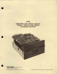
1.3 DESCRIPTION OF DRIVES
Each Micropolis OEM Floppy Disk Drive (see figure 1-1) consists of a drive
mechanism and a drive electronics PCBA. A protective mounting sleeve, not
shown in figure 1-1, is optional. Since the drives are intended to be
mounted within an OEM system and receive regulated DC power from the system,
an enclosure and the regulated power supplies are not included. Also, since
the system requirements determine the drive controller specifications, the
controller is not supplied by Micropolis.
The following OEM Floppy Disk Drives are described in this manual:
a.
b.
c.
Model 1015 MOD I.
Model 1015 MOD II.
Model 1016 MOD II.
MOD I drives have a track density of 48 tracks per inch (TPI) with a total of
35 tracks. MOD II drives have a track density of~ 100TPI with 77 total tracks.
The difference in track density and total tracks results from using a different lead screw in the positioner, a different read/write/erase head, and
different components and adjustments on the PCBA.
Figure 1-1.
Micropolis OEM Floppy Disk Drive (typical)
1-2
102001A
Table 1-1 summarizes the specifications of the OEM Floppy Disk Drives.
TABLE 1-1.
SPECIFICATIONS
Physical (without sleeve)
Height
Width
Depth
Weight
3 3/8 in (86 nm)
5 7/8 in (149 mm)
8 1/2 in (216 mm)
3.9 lbs (1.77 kg)
Environmental
Operating temperature: 50°-105°F (10°-41°C)
Relative humidity: 20%-80% (without condensation)
Power Dissipation
Standby
Operating
8 watts
16 watts
Unformatted capacity (per drive)
1015 MOD I
Single Density
Double Density
110 Kbytes
220 Kbytes
1015 MOD II
Single Density
Double Density
240 Kbytes
480 Kbytes
1016 MOD II
585 Kbytes
Drive Characteristics
102001A
Rotational speed
Rotational latency
Drive motor start time
Head load time
300 rpm
100 milliseconds (average)
1 second
75 milliseconds
Access time
Track-to-track
Settling time
Transfer rate
30 milliseconds
10 milliseconds
250 Kbits/second
1-3
TABLE 1-1.
SPECIFICATIONS (cont.)
Drive Characteristics (cont.)
Recording density
1015/MOD I: 5162 bits per inch
1015/MOD II: 5248 bits per inch
1016/MOD II: 6380 bits per inch
Track density
MOD I: 48 tracks per inch
MOD II: 100 tracks per inch
Total tracks per surface
MOD I: 35
MOD II: 77
Media size:
5~
inch
Reliability/Maintainability
MTBF
MTTR
8000 hours
0.5 hour
Media life:
Head life:
3 x 10 6 passes on single track
10,000 hours
Soft error rate:
Hard error rate:
Seek error rate:
1 in 10 9
1 in 10 12
1 in 10 6
1.4 MAINTENANCE PHILOSOPHY
Micropolis Floppy Disk Drives are designed for trouble-free operation. Most
maintenance operations require a high degree of technical sophistication, the
proper training, and the proper equipment. Non-technical end users should
NOT attempt to perform either preventive or corrective maintenance.
1.4.1 End User Maintenance
The isolation and correction of faults within the disk drive requires
sophisticated test equipment and experience in the field of analog and digital
troubleshooting. Unless you have been trained by Micropolis and have the
necessary tools and equipment s you should make no attempt to perform tests,
adjustments, or replacements. If the checks in table 1-2 do not isolate or
correct the fault, notify the appropriate service personnel.
1-4
102001A
TABLE 1-2.
END USER TROUBLESHOOTING
Symptom
Probable Cause/Corrective Action
Motor does not turn
and select indicator
never lights.
No power to drive.
Select indicator
never lights.
1.
2.
3.
Interface cable not connected to drive or
plugged into controller.
Controller not plugged into computer or
computer not turned on.
Computer power supply voltages are
incorrect.
Drive is always
selected.
Interface cable is reversed at one end.
Program cannot be
loaded (procedure in
the system user's
manual has been
followed).
Inadequate memory - the memory requirements for
the high data transfer rates associated with the
Micropolis drives may exceed the capabilities of
the computer's memory. Try substituting memory
made by a different manufacturer.
Permanent I/O
errors occur.
1.
2.
3.
4.
NOTE:
Inadequate memory (see above).
Computer timing problem - there have been
many changes/improvements made to·various
brands of microcomputers to improve operation with disk memory systems. Check with
Micropolis Product Support and/or the
computer manufacturer to determine whether
these changes have been incorporated in
your system.
Drive fault - try using a known good drive.
Controller fault - try substituting a known
good controller.
This chart is intended only as a first level diagnostic aid for system
level troubleshooting. Section V contains a more thorough guide for
qualified service personnel to troubleshoot the disk drive.
1.4.2 Dealer Service Centers
Micropolis dealers and OEMs that have received formal training on the theory
of operation and maintenance of Micropolis equipment, and that possess
adequate test equipment and spare parts, are designated as Micropolis Service
Centers. These Service Centers are best able to provide high quality and
timely warranty and nonwarranty service on Micropolis products.
102001A
1-5
1.4.3 Micropo1is Repair Depot
Micropo1is maintains a fully equipped repair depot which provides warranty
and nonwarranty repairs and emergency spares support. Contact Micropolis
Customer Service to obtain a Return Goods Authorization (RGA) prior to
returning any drive for repair.
1.5 MAINTENANCE EQUIPMENT REQUIRED
The following tools, test equipment, and special items are required for
maintaining and/or servicing Micropo1is OEM Floppy Disk Drives. Where a
manufacturers part number is given, equivalent equipment may be used.
a. Tools:
3/16-inch nut driver
1/4-inch nut driver
Screwdriver, Phillips #1
Tweezers - Clause 231
7/64-inch hex driver
7/64-inch hex key, long handle
3/32-inch hex key
Spring Hook Set - National Camera S1390
1/4-inch combination wrench
5/16-inch box end wrench
3/8-inch box end wrench
Pot screwdriver - Bouvus H-90
Spring scale, 0-10 lbs
Cotton swabs
b. Test Equipment:
Oscilloscope - Tektronix 453
Digital mu1timeter - Simpson 461
Frequency counter, 0 to 10 MHz (optional)
Micropo1is Flexible Disk Exerciser, Model 1099 (optional)
c. Special Items:
Freon TF or isopropyl alcohol
Maintenance standoff - Micropolis 100100-02-3
Lubricant, Saunders Magnalube - Micropolis 732-0001
C.E. Alignment Diskette - Dysan 282 (see paragraph 1.5.1)
1-6
IJ2JOIA
1.5.1.
Alignment Diskette
The alignment diskette is a Dysan PIN 282 (Micropolis PIN 641 0590-1).
following tracks of this diskette are used:
Track 1 (MOD I) }
Track 5 (MOD I I)
Index/photo transistor alignment
Track 16 (MOD I }
Track 36 MOD II)
0 switch setting)
The
( ) I for
Radial IIcat's eye" alignment, also reference track
absolute track positioning' (i .e., correct track
Used in conjunction with track 1 (MOD I) or track 5
Track 35 ((MOD I) } J (MOD I I) for setti ng of azimuth (perpendi cu 1ar head
Track 76 MOD II) 1 movement).
CAUTION
Care should be exercised not to erase
the prerecorded alignment tracks. Do'
not defeat or override the write protect feature of the drive or diskette.
Do not install the alignment diskette
in a drive with a $uspected-write logic
or write protect logic failure. NEVER
unplug the drive's head connector with
any diskette installed.
1.6 PREVENTIVE MAINTENANCE
Micropolis Floppy Disk Drives do not require ,preventive maintenance when used
in the following environment:
a.
b.
c.
Dustfree
65° to 80° ambient
Eight hours of operation per day (or less), with power applied,
motor running, and a head load cycle of 25% or less.
If the operating conditions exceed these, the preventive maintenance operations specified in table 1-3 should be performed.
102001A
1-7
TABLE 1-3.
PREVENTIVE MAINTENANCE SCHEDULE
-
Time
Required
(Hours)
Manual
Paragraph
Reference
Operation
Frequency
Replace Head
Load Pad
2000 hrs of
diskette access
0.1
6.5
Clean Head
2000 hrs of
diskette access
0.1
1.6.1
Lubricate Lead
Screw
2000 hrs of
diskette access
0.1
1.6.2
Replace Drive
motor
5000 hrs of
motor operation
0.5
6.4
Lubricate Latch
Mechanism
Every two years
0.1
1.6.3
NOTE:
These maintenance operations are required only when operating
conditions exceed normal.
1.6.1 Cleaning the Head
CAUTION
Rough or abrasive cloth must NOT be
used- to clean the head. Use only i sopropyl alcohol or DuPont Freon TF; use
of other solvents, such as carbon tetrachloride, may damage the head lamination
'
adhesive.
To gain access to the head, it will usually be necessary to first remove the
drive from the system enclosure (see paragraph 6-2 for procedure).
Clean the'magnetic head with a soft, lint-free cloth or cotton swab moistened
with isopropyl alcohol or DuPont Freon TF. Wipe the head carefully to remove
all accumulated oxide and dirt. Dry the head with a lint-free cloth.
NOTE
The head must be cleaned after head
load pad replacement.
1-8
102001A
1.6.2 Lead Screw Lubrication
To gain access to the lead screw, first remove the drive from the system
enclosure (see paragraph 6-2) and then temporarily move the PCBA out of the
way (see paragraph 6-3, but do not cut the head cable tie wraps).
Prior to lubrication, the stepper motor lead screw should be cleaned. Wipe
the lead screw with a lint-free cloth lightly moistened with isopropyl alcohol.
CAUTION
Do not contaminate the magnetic recording head or the head load pad with
lubricant. Damage to the diskette's
recording surface can be caused by
lubricant deposited on the head or head
load pad.
Lubricate the lead screw and the part of the head carriage that rides on the
platen with a thick coat of Saunders Magnalube (Micropolis PIN 732-0001-6).
1.6.3 Latch Mechanism Lubrication
To gain access to the latch mechanism, it will usually be necessary to first
remove the drive from the system enclosure (see paragraph 6-2 for procedure).
To ensure smooth, positive action of the door latch mechanism, apply a heavy
coat of Saunders Magnalube (Micropolis PIN 732-0001-6) to the entire latch
mechanism.
1.7 CORRECTIVE MAINTENANCE
Corrective maintenance consists of isolating a fault to a defective or
misadjusted assembly or component, replacing or adjusting the assembly or
component, and verifying that the repair has eliminated the fault. The
following suggested sequence will help to make the most effective and
efficient use of this manual:
a. Isolate the malfunction to the faulty assembly, subassembly, or
component. See the Troubleshooting Chart in Section 5.
b. If a more thorough understanding of the operation of a circuit or a
mechanical or electrical component is desired, see the Theory of
Operation in Section 3. The circuit descriptions reference the
Assembly Drawings and Schematic Diagrams in Section 8.
c. If necessary, test the suspected circuit or mechanical assembly.
See Section 4, Tests and Adjustments. Also using Section 4, it may
be possible to perform an adjustment to eliminate the fault.
102001A
1-9
d.
e.
f.
Order a replacement component, subassembly, or assembly. See
Section 7, Parts List.
Replace the component, subassembly, or assembly. See Section 6,
Removal and Replacement Procedures.
Adjust and/or test the circuit or mechanism after replacing the
part. See Secti on ,4, Tests and Adjustments.
1.8 SPARE PARTS
Section 7 provides part numbers for the replaceable parts of the OEM Floppy
Disk Drives. Information on recommended spares levels for field engineers
and for repair depots can be obtained from Micropolis Customer Service.
These levels should be maintained to reduce down-time.
Routine orders for spare parts should be placed through Order Entry, not
Customer Service. Orders for routine spares are treated and scheduled in
the same manner as orders for disk drives, accessories, etc.
Emergency spares will be shipped within 24 hours and will not be discounted.
Emergency spare orders should be placed with Customer Service.
An identification label is attached to the underside of the chassis, near the
large pulley. It shows the model number; part number,'and serial number of
the drive. These numbers should be quoted in all correspondence. Drives
shipped with the optional protective sleeve have the label attached to the
back panel.
1-10
l02001A
SECTION II
INSTALLATION
2.1
INTRODUCTION
This section provides information necessary for installing the drive.
Included are instructions for unpacking the drive (and re-packing the drive
for shipment if necessary),. visually inspecting the drive, installing the
drive, configuring multi-drive disk systems, and supplying power.
2.2 UNPACKING THE DRIVE
The drive is packed so as to minimize the possibility of damage during
shipment. Use the following procedure to unpack the drive, and save ALL
packing material in case it is necessary to re-pack the drive for shipping.
a. Place the shipping carton on a flat work surface.
b. Carefully cut the sealing tape on the carton top; open the top flaps.
c. Remove and SAVE the six-inch wide foam strip that covers the inner
carton.
CAUTION
Use extreme care when handling the
inner carton; the drive (inside it) is
subject to damage if dropped.
d.
e.
Carefully remove the inner carton and place it on the work surface.
Cut the sealing tape on the carton top; open the top flaps.
CAUTION
When the drive and fiberboard base are
removed from the carton, the drive
mechanism and circuit board will be
exposed. Handle VERY carefully.
f.
g.
102001A
Lift the drive out of the carton. SAVE the cardboard insert in the
carton.
Remove the three screws (and spacers) that hold the drive to the
fiberboard base. SAVE the base, the screws, and the spacers. In
addition, save both cartons and the six-inch and ten-inch foam
strips.
2-1
2.3 RE-PACKING THE DRIVE FOR SHIPMENT
If it is necessary to re-pack the drive for shipment, the following procedure
must be used.
CAUTION
Do not attempt to ship the drive except
in the original packing.
a.
b.
c.
d.
e.
f.
g.
Attach the drive to the fiberboard shipping base using three screws
and ,spacers.
The drive, suspended from the base, fits in the smaller (inner)
carton; the base rests on the cardboard insert.
Close the flaps and seal with tape.
If the ten-inch wide foam strip has been removed from the larger
(shipping) carton, form it into a IIU-shaped" cradle in the carton.
Place the inner carton (with the drive) in the foam cradle, with
equal space on either end.
Form the six-inch wide foam strip into a wide inverted U, and place
it over the inner carton, with the legs of the U inside the shipping
carton on either end of the inner carton.
Close the flaps and seal securely with tape.
2.4 UNPACKING/RE-PACKING DRIVES WITH SLEEVES
Drives shipped with the optional protective sleeve are not attached to a
fiberboard shipping base, and the inner carton does not have a cardboard
insert. The drive is enclosed in a large plastic bag:-wrapped in Kimpack
shipping insulation, and placed directly in the inner carton.
2.5 VISUAL INSPECTION
When the drive is unpacked, inspect it for any damage.
of any kind is evident, notify the carrier at once.
If shipping damage
NOTE
Do not return the damaged drive until
the shipping company inspector has
reviewed the damage, since an insurance
claim will be made.
2-2
l02001A
2.6
INSTALLING THE DRIVE
2.6.1 General Guidelines
The following general guidelines should be adhered to when planning the
installation:
a. The ambient temperature must be in the range of 50°-105°F (10°-41°C).
b. Do not install a drive close to sources of strong electromagnetic
or electrostatic fields (i.e., large transformers, CRTs, motors,
etc. ) .
c. Avoid dirty, dusty, or smoky areas.
d. Avoid static discharging to any part of the system (use anti-static
spray on carpets).
e. Ensure that adequate regulated DC power (as specified in section 2.8)
is available.
f. For drives with the optional protective sleeve, ensure that the
cooling slots are not obstructed.
2.6.2
Specific Mounting Requirements
Refer to figure 2-1 and ensure that the following mounting requirements are
met:
a. The drive may be mounted in any orientation except upside down. If
the drive is to be mounted with the bezel ~, it should be ordered
as such so the disk eject system can be suitably adjusted.
b. Use the recommended panel opening given in figure 2-1, and insert
the drive through the panel opening from the front.
c. On no account should the mounting scheme rely on the plastic bezel
for support.
d. The three holes in the chassis that are used to hold the drive to the
fiberboard shipping base are NOT to be used for mounting the drive.
Use the two front and either one of the rear plastic mounting nuts on
the chassis edges. For drives with the optional protective sleeve,
use the outside two holes on either side, or the three holes on the
sleeve bottom, or (preferred) the two front and either one of the
rear holes that secure the sleeve to the drive chassis.See figure
2-1 for details. Spacers against the sleeve should be at least 0.5
inch outside diameter.
e. Use care that mounting screws do not protrude more than 0.2 inch
into the drive mechanism.
f. The holes in the base chassis to which the drive is to be mounted
must have sufficient clearance to allow for tolerances and thermal
expansion. This also precludes the use of flat-head screws.
g. Mounting brackets should be made of 0.060 inch thick (min) steel,
attached to the base chassis, and with holes large enough that when
all screws are tight, stress is not communicated to the drive.
102001A
2-3
_
20
(.51)
•
11
8.30
(21. 08)
5.88
(14.94)
5.72±.02
(14.53)
--!I
n
3.22
(8.18)
~~
.85
I
(2.16)-1
.45
(1.14 )
__________~~____~~~--1
.----(1ri:~~)---J ~....
PLASTIC MOUNTING NUTS. 6-32~ l PER SIDE.
ON DRIVE CHASSIS. USE BOTH FRONT MTG
NUTS AND EITHER ONE REAR MTG NUT FOR
EXTERNAL MOUNTING.
SUGGESTED PANEL OPENING:
5.825
14.795
DRIVE CHASSIS
::~~~ BY 3~305 ~:~~~ INCHES
~:~~~ BY 8.395 ~:~~~ CM
DIMENSIONS:
INCHES
\eM)
Figure 2-1. Drive Mounting Details
(Sh 1 of 2 - Without Optional Protective Sleeve)
2-4
l02001A
20
11-
8.30
(21. 08)
(. 51) )
'
6-32 HOLE, FAR SIDE
(BOTTOM), 3 PL.. MAY
BE USED FOR
EXTERNAL MOUNTING.
/
/
r- T
TOP
2.00
(5.0B)
I
5 .88
(1 4.94 )
t
-
-¥T
+_1
2.00
.850
(2.16 )
J
r
n
(L
.400
( 1.02)
(5.0B)
I
4.800
(12.19)
SLEEVE HOLES, 6-32, 3 PER SIDE.
OUTER 2 SCREWS EACH SIDE CAN BE
REMOVED AND USED FOR EXTERNAL
MOUNTING.
5 09
(12.93)
3.12
(7.92)
1.56
(3.96)
/
/
t
+-
~~+-------~ -~--
(2.16)~
.88
(2.23)
-+.----~~-
'-
I
1
/
3.38
.85
5.8 o
{14.7 3)
- --,-\
4.00
( 10.16)
(8.3 3 )
i
-.-L
f
.4 5
f
DRIVE CHASSIS (1.14)
\
SLEEVE ATTACHES TO PLASTIC MOUNTING NUTS,
6-32, 2 PER SIDE ON DRIVE CHASSIS.
PREFERRED FOR EXTERNAL MOUNTING: USE
BOTH FRONT MTG NUTS AND EITHER ONE
REAR MTG NUT.
SUGGESTED PANEL OPENING:
5.825
~:~6~
BY 3.305
~:~~~
INCHES
14.795
~:~i~
BY 8.395
~:~i~
CM
DIMENSIONS:
Figure 2-1. Drive Mounting Details
(Sh 2 of 2 - With Optional Protective Sleeve)
l02001A
3.2 8
2-5
INCHES
-reM)
2.7 MULTI-DRIVE DISK SYSTEMS
Micropolis 1015/1016 drives can be configured into multi-drive systems, with
up to four disk drives. This section provides the technical information
necessary to implement a multi-drive system.
2.7.1 Daisy-Chaining Drives
A multi-drive system consists of two, three, or four drives, connected to the
host controller with a IIDaisy-Chain" interface cable. A typical multiple
drive system is shown in figure 2-2.
DAISY-CHAIN INTERFACE CABLE D
DISK
CONTROLLER
BOARD
DRIVE 3
!lADD-ON"
DRIVE 2
IIADD-ONII
DRIVE 1
DRIVE 0
IIADD-ONII
"MASTER
II
COMPUTER
Figure 2-2. Typical Multiple Drive System
The interface cable consists of a set of common input/output lines and four
disk select lines. All lines are applied to all drives. Address comparison
logic in each drive enables the drive to respond to one and only one disk
select line. (Instructions for setting the address comparison logic are given
in paragraph 2.7.2.) A single drive may be set to respond to address 0, 1, 2,
or 3 (normally, if there is only one drive it will be set for address 0). In
a multi-drive system, no two drives may be set to respond to the same disk
select line.
In a multi-drive system a distinction is made between the "master drive and
the lIadd-onli drives. The master drive includes a resistor network for
terminating the interface lines. An add-on drive does not contain terminators.
All 1015/1016 drives are shipped as master drives; instructions for converting
a master drive to an add-on drive are given in paragraph 2.7.2. The master/
add-on distinction does not effect the address selection; any drive may have
any address.
ll
2-6
102001A
The following Daisy-Chain interface cables are available from Micropolis:
Model No.
1083-02
1083-03
1083-04
Name
Interface Cable B
Interface Cable C
Interface Cable D
Usage
Two drives
Three drives
Four dri ves
The Daisy-Chain interface cable is connected in place of the standard
Interface Cable A. The Master drive (the one with the terminators) must be
connected to the last connector on the cable, i.e., the furthest from the
controller, to provide proper termination.
2.7.2 Master to Add-On Conversion
To convert a master drive to an add-on drive, -remove the terminators as
follows:
a. Locate the terminator resistor pack (U15 on a Single A PCBA, U17 on
a Single B PCBA).
b. With a small flat-blade screwdriver, carefully pry the resistor pack
from its socket. The resistor pack should be saved in case it is
desired to convert the drive back in the future.
2.7.3
~ddress
Changing
To change the drive address, reconfigure the address comparison logic as
follows:
a. Locate address jumper locations WI through W4 on the PCBA. Model
1015/1016 drives are shipped with WI installed. Only ONE of the
jumpers WI through W4 may be installed on a PCBA.
b. Remove the jumper from the socket. Replace the jumper in the socket
for the desired address, as follows:
Drive
Address
0
1
2
3
l02001A
Install
Jumper
WI
W2
W3
W4
2-7
No
Jumper
W2,W3,W4
Wl,W3,W4
Wl,W2,W4
Wl,W2,W3
2.8 SUPPLYING DC POWER
The 1015/1016 drives require user-supplied DC power. +5V and +12V regulated
DC power is supplied to 10 pin connector J5 on the drive PCBA. The mating
connector is Molex Part No. 22-01-2101. Pin assignments are:
Pin
1
2
3
4
S
6
7
8
9
10
Connection
Not used
Key
+12V return
+12V
Not used
+SV return
+5V
Not used
Not used
Not used
Current requirements are as follows:
+12V
+ 5V
Standby
(Dopr Open)
0.3A
O.SA
Operating
Average
Peak
1.0A
1.3A
O.SA
0.5A
The +5V return and +12V return must be connected together at the power supply.
The drive chassis must be connected to the computer chassis or directly to
earth gro~nd.
2-8
102001A
SECTION III
THEORY OF OPERATION
3.1
INTRODUCTION
This section describes the operation of the drive. First the drive mechanism
is described, followed by the signal interface, and then the drive electronics
PCBA (both the Single A and the Single B PCBAs are described). Each of these
components is described in sufficient detail to assist fault isolation and
troubleshooting.
3.2 DRIVE MECHANISM
The drive mechanism, shown in figure 3-1, consists of the following elements:
a.
b.
c.
d.
e.
Spindle Drive System
Head/Carriage Assembly
Positioner Control Mechanism
Electrical and Mechanical Interlocks
Index Sensor
Figure 3-1.
l02001A
Typical Drive Mechanism
3-1
All drive mechanisms use the same mechanical elements except:
a. The lead screw has a pitch of 8.33 threads per inch for a 100TPI
(MOD II) drive, or 4 threads per inch for a 48TPI (MOD I) drive.
b. A different magnetic head is used for 100TPI (MOD II) drives, having
narrower read/write and erase gaps than the 48TPI (MOD I) dfives.
3.2.1.
Spindle Drive System
The spindle is driven by an integral DC motor/AC tachometer (which provides
a closed-loop velocity servo action) via a belt which yields an 8-to-l speed
reduction from motor to spindle. When the drive door is closed, a springloaded clamp attached to the receiver assembly lowers and forces the diskette
over a precision cone on the spindle assembly. The cone profile is such as
to provide an interference fit centering the diskette on the spindle.
Centering is promoted by the rotation of the spindle during the diskette
clamping process. The door switch is adjusted so the spindle begins to rotate
before the diskette is clamped to the spindle.
3.2.2 Head/Carriage Assembly
The head consists of a ferrite read/write (R/W) element and two tunnel erase
elements mounted in a barium titanate slider. The head is mounted in a
carriage assembly which is both supported and driven by the lead screw via a
steel follower and is also referenced to the platen. When the drive is
selected, the head load solenoid is energized, allowing the load arm and
pressure pad to force the diskette into contact with the head with a load of
15 to 18 grams. A foam rubber pad on the solenoid arm ensures the diskette
jacket is loaded against the platen surface. In this wayan accurate
relationship is established between the diskette and the head surface yielding
a controlled penetration. When the head load solenoid is deenergized, the
diskette has little or no contact with the head.
3.2.3
Positioner Control Mechanism
The head/carriage assembly is positioned by a four-phase permanent magnet
stepper motor via a ground stainless steel follower. The positioner control
and lead screw are preloaded against a bearing in the spindle housing by a
flexure spring. This referencing technique substantially removes the base
plate from the thermal expansion and mechanical stability loops.
The lead screw pitch is chosen so that four "ministeps " are taken to move
one track. This reduces by a factor of four the effects of stepper motor
inaccuracy and hysteresis effects caused by friction. Sequencing of the
phases is organized by the control electronics (see paragraph 3.4.5 for
Single A or 3.5.6 for Single B). A track zero switch is mounted on the
chassis such that an extension of the head carriage activates the switch
between tracks 0 and 1. A mechanical stop prevents the carriage from moving
behind the track zero position.
3-2
l02001A
3.2.4
Interlocks
There are two electrical switch interlocks and a mechanical interlock.
The door open switch is an interlock that deenergizes the drive motor and
causes loss of the Ready status when the door is open. The switch is adjusted
to close as soon as the receiver assembly is lowered so the motor is rotating
before the diskette is actually clamped to the spindle.
The write protect switch senses the presence or absence of a notch in the
diskette jacket for write protection. The normal write protect convention
specifies that the diskette is write-protected if the write enable notch is
covered by a write protect tab, thereby keeping the switch actuator from
entering the notch.
The mechanical interlock is a mechanism associated with the diskette ejector,
that prevents the door from closing if no diskette has been loaded into the
drive receiver assembly. It also ejects the diskette when the door handle
is lifted after the door is opened.
3.2.5
Index Sensor
Index and sector information is sensed by a combination of a light emitting
diode (LED) mounted on the receiver assembly and an index transducer (photo
transistor) mounted in the platen. Index-to-data adjustment is provided by
moving the platen assembly.
3.3
INTERFACE
This section describes the interface signals and timing requirements from
a general viewpoint. This description applies to drives using either the
Single A or the Single B PCBA. Specific references are covered in the
appropriate sections of the Single A and Single B PCBA descriptions.
Interface connector Jl is located on the drive electronics PCBA. Jl provides
the interface connection between the disk drive and the host controller. The
interface consists of 11 input lines and 5 output lines. All interface lines
are low true with the following logic levels:
True = Logic Zero
False = Logic One
l02001A
= 0= 2.5 -
3-3
O.4V
5.25V
A maximum of four drives can be connected to one host controller with a daisy
chain cable. Termination resistors for the input lines are provided on the
drive electronics PCBA (for daisy chain connections, they are installed in
the last drive only). Figure 3-2 shows the typical receiver/driver characteristics for the interface. Either flat cable or twisted pairs may be used,
with a maximum total cable length of 20 feet.
r--
CONTROLLER
20 FEET
DRIVE
MAXIMUM
r-- - - - - I
I
7438
7416
I
OR EaUIV
105-0HM FLAT CABLE
OR TWISTED PAIR
220-0HM
7404
INPUT
OR eaulv
I
HIGH
HIGH
TRUE
TRUE
330OHM
I
5V
7404
OR EaUIV
HIGH
I
I
I
LOW TRUE
7438
OUTPUT
7416
OR EaUIV
HIGH
TRUE
TRUE
L ____ ~___
I
~
_ _ _ _ --1
NCTt:S
Input Lines:
TRUE = Logic Zero = 0 to O.4V @ 25 ma max
FALSE = Logic One = 2.5 to S.2SV @ 0 ma (open)
TRUE = Logic Zero = 0 to O.4V @ 48 ma max
FALSE = Logic One = 2.5 to S.2SV @ 250 ua max (open col1ectorl
INPUT LINES ARE TERMINATED IN LAST DRIVE ONLY.
USER MAY USE 150 OHM TO +5V TERMINATION ON
OUTPUT LINES IF D~SIRED.
Output Lines:
Figure 3-2.
Interface Characteristics
3-4
l02001A
Table 3-1 lists the interface signals. Detailed information about each signal
is given in the Single A and Single B PCBA descriptions. Figures 3-3, 3-4,
and 3-5 show the general timing requirements.
TABLE 3-1.
Jl Connector Pin
Si gna 1
2
4
6
8
10
12
14
16
18
20
22
24
26
28
30
32
34
Note:
102001A
Ground
1
3
5
7
9
11
13
15
17
19
21
23
25
27
29
31
33
INTERFACE SIGNALS
Signal
Description
Source
HDLD/
Head Load
Spare
Ready
Sector/Index Pulse
Drive Select 1
Drive Select 2
Drive Select 3
Drive Motor On
Step Direction
Step Command
Write Data
Write Gate
Track Zero
Write Protect
Read Data
Head Select
Drive Select 4
Controller
-
RDY/
SECP/
DSI/
DS2/
DS3/
MTRN/
DIRN/
STEP/
WDA/
WRT/
TRK0/
WPT/
RDA/
HSLT/
DS4/
-
Drive
Drive
Controller
Controller
Controller
Controller
Controller
Controller
Controller
Controller
Drive
Drive
Drive
Controller
Controller
Jl Mating Connector ;s Scotchflex PIN 3463-001 or equivalent.
3-5
DC Power
--.J
Motor On
Drive
J
Selected _ _ ___
I~I
ROY/
~0.5
us max
---'-~-I-,-.-.I~I~~~_l_s_ec_m_ax________________________________________
~0.5 us max
I
Valid TR K0 / , - - - - - - ,
WPT/
.~__--------------------------------------------
Valid SEep/
Output
,--------------------------------
I
HoLD/
I
DIRN/
1
I
I~I-------------------ns min
..I
1~250
lJLJLJ
STEP/
~I
WRT/
WDA/
L
Valid RDA/
I~.- - -
40 ms
~
I
I~
min ~
e--________. .
I
I-+--I ULJl.JlflJ U,...---II '--.. ~
30 ms min
....
~
75 ms min
1 sec min
850 us
max~
8 us max
40msmax~J
~
L
75 ms max
~
.....- - - - - - - - - - - - - 1 sec max
Figure 3-3. Major Signal General Timing Requirements
3-6
l02001A
STEP OUT
STEP IN
DIRN/
250 ns min.
~
STEP/
1-
U
~I
...-,Uf-4-
250 ns min.
I
INHIBIT READ
AND WRITE
I~
Figure 3-4.
04
ms min.
40 ms min.
r
250 ns min.
U
U
I
.. -
30 ms min
~
40 ms min.
..I
Positioner Control General Timing Requirements
13
15
14
I
0
SEep/
2
S
I~
.1
12.5 ms
20.65ms
Figure 3-5.
l02001A
U
6.25 ms
~ ~
::!:0.325 ms
Index/Sector General Timing Requirements
3-7
3 ms ±1ms
3.4 SINGLE A DRIVE ELECTRONICS
The Single A Drive Electronics PCBA, PIN 100071, contains the control
circuitry for the drive. The Single A PCBA controls the operation of the
drive mechanism as well as reading and writing of data. The PCBA connects to
the drive mechanism with a number of molex connectors; the interface connection
to the host controller is discussed in section 3.3.
The Single A PCBA consists of the following functional elements:
a.
b.
. c.
'd.
e~
f.
Interface Circuits
Motor Control Circuit
Read Circuitry
Write Circuitry
Positioner Control Circuit
Miscellaneous Control Circuits
These elements are shown in block diagram form in figure 3-6.
GJ
CLT
$1 I f'
--
POSITIONrR
5HP
.JIo.
-lI""
......
CONTROL
.......
DIR!Cl.ON
niH/\;
The paragraphs
AND
STEP MOTOR
DRIVERS
INTERFACE
CIRCUIlS
I
...
....
TRK 0
I
...
SBSY
...
P3
,
J3
~
i--
~
SWITCHES
TRANSDUCER
AND SOLENOID
WRITE PROTECT
...
DRIVE
ASSEMBLY
P4/ J4
,
~
1..-,---
~r
~
1
SERIAL WRITE DATA
.......
...
......
I
.......
I
I
J6
I
I
P6
I
A~
~
J4
I
P4/2
I
I
WRITE/ERASE
WRITE
WRITE ENABLE
WRT
~
.--i""
...
INDEX
........
WDA
I
J3
TRACK 0
~
WPT
PJ/2
JIll"
~
SECP
WEN
~
~
.....
SERIAL READ DATA
RD
.....
~
MTRN
READ
MOTOR ENABLE
....
JIll"
......
......
ROY
READY
MOTOR
CONTROL
LOGIC
READ
.....
-
..........
........
MOTOR DRIVE
TACHOMETER
I-
Figure 3-6.
Single A Overall Block Diagram
3-8
l02001A
that follow provide a detailed explanation of each functional element. The
circuit descriptions are supported by block diagrams; detailed schematic
diagrams are located in Section 8 of this manual. The schematics are
referenced by drawing and sheet number to facilitate their use.
3.4.1
Interface Circuits (Sh 2 of Owg 100072)
The interface circuits consist of line receivers, input terminators, line
drivers, and drive selection logic. Input signals are terminated by
220/330 ohm terminator pack U15. (As discussed in paragraph 2.7.1, add-on
drives have the terminator removed.)
A jumper in one of the positions WI, W2, W3, or W4 causes the drive selection
logic to respond to the corresponding drive select input line OSI, OS2, OS3,
or OS4. The appropriate select line is terminated by Rl and received by
UI6-2. The select signal gates the output signals directly via drivers UI-6,
UI-8, Ul-ll, and Ul~3, and indirectly via U16-12 (on Sh 7 of Owg 100072) for
the read data signal. The select signal also drives a LED panel indicator via
driver U20-4, to indicate that the drive is selected.
3.4.2 Motor Control Circuit (Sh 8 of Owg 100072)
The motor control circuit is a closed loop servo, which controls the spindle
drive system. The spindle drive consists of a DC motor and AC tachometer
mounted on a common shaft. The DC motor shaft rotation is converted by the
tachometer to an AC signal whose amplitude is proportional to the speed of
the motor. This feedback signal is rectified and filtered to produce an
equivalent DC signal. An operational amplifier compares the feedback signal
with a reference level generated on the PCBA. The net output from the
operational amplifier drives a power amplifier which in turn powers the DC
motor. Figure 3-7 is a block diagram of the motor control circuit.
+12
DC MOTOR
RECT
..-.--~
COM PARATOR
~----'----1
POWER
AMP.
CURRENT
LIMIT
AC TACHOMETER
R66
SPEED ADJUST
Figure 3-7.
.02001A
Single A Motor Control Circuit Block Diagram
3-9
a.
b.
c.
Rectifier and Filter. The AC tachometer signal enters the Single A
PCBA at J4-14 and -15. Diode CR20 and resistor R64 form a half-wave
rectifier whose output is filtered by capacitor C41. The filtered
signal is applied to the next stage through resistor R68.
Comparator and Reference Circuit. Operational amplifier U6 ~ompares
the output of the previous stage with a reference level established
by potentiometer R66 and its associated components. The reference
voltage is developed by a voltage divider network consisting of
resistor R65and zener diode CR21. Potentiometer R66 is connected
across the constant voltage source CR21 and in series with temperature
compensating diode CR22 and resistor R67. The effect of this network
is to produce a temperature compensa~ed adjustable reference level
at input U6-3. Resistors R70 and R72 form the feedback loop with a
DC gain of 36. The output of U6 feeds the power amplifier drivers
through DC coupling network R73, R74.
Power Amplifier Circuits. The power amplifier circuits consist of
Darlington pair transistor Q5, current limiter circuit Q4, and
associated components. The operation of power amplifier driver Q5
is controlled by the state of the MOT signal. This signal is
coupled into the base of Q5 by diode CR23.
When MOT is low, CR23 conducts, and the base of Q5 goes to 0.8V,
cutting off Q5. When MOT goes high, CR23 is cut off, allowing the
base of Q5 to attain its operational value (approx. 1.4V).
Resistors R77, R75, and R76, and transistor Q4, form a feedback
circuit that reduces the current surge caused by motor startup.
When the motor-on command is received, transistor Q5 goes into
saturation and collector current would normally rise to a larger
value since the motor is still stationary. However, the current
feedback network consisting of Q4 and. its associated components
will limit this initial surge to a maximum of 0.8 amp. Resistor
R77 provides a convenient point to monitor the motor current. Diode
CR24 protects Q5 from inductive kickback caused by commutation. L6,
C37, C38, C39, and C40 provide filtering to prevent high frequency
transients generated by the motor from propagating into the drive
electronics through the power supply.
3-10
l02001A
3.4.3 Read Circuitry (Sh 7 of Dwg 100072)
The read circuitry processes the low-level information from the read head
during the read cycle, reshaping it into a digital pulse stream. Figure 3-8
is a block diagram of the read circuitry. The +12V supplied to the elements
in these circuits is filtered through L5 to provide additional noise isolation.
Voltage divider R47, R48 and filter capacitor C22 develop a reference voltage
(referred to as V1) of approximately 6V used in the circuits discussed below.
RDI
A
81
INPUT
CLAMP
DIHER
ENTIATOR
FilTER
AMPLIFIER
COM PARA
TOR
DIREC
llONAl
OM
SHOT
SYSTEM
RD2
FROM READ WRITE
SWITCH CIRCUIT
RS'!
SE
LI
WBSY
Figure 3-8.
a.
b.
c.
102001A
Single A Read Circuitry Block Diagram
'Input Clamp. The low-level signal (approx. 1.5 mV pp) from the read
head is fed to differentiator U24. Input diodes CR18 and CR19
constitute a clamp circuit that prevents transients generated by the
write circuit from propagating through the read circuits. The
junction of diodes CR18 and CR19 at V2 is held at approximately
+6.7V. This voltage is generated in voltage divider R37, R36, R38
(refer to the discussion of PSEN generation in paragraph 3.4.4a).
Differentiator. The differentiator consists of U24 and its
associated components. This element, with U22 and U23, functions as
a peak detector that generates the signal illustrated in the timing
diagram of figure 3-9, which shows the read waveforms for a sequence
of 1I11S.11 Thus the output of U24 crosses the zero-base line each
time a peak is detected on the input signal. Capacitor C25 yields
the required 6 dB per octave rising characteristic of a differentiator. Resistor R51 terminates this characteristic at 250 kHz.
This stage has an approximate gain of 40 at 125 kHz.
Filter. The balanced output of U24 at pins 7 and 8 is applied to
an LCR filter that provides a phase shift as a function of frequency.
This is the linear function required for true data reproduction of
the read data. R52 and R53, and V1, maintain the read signal at the
center of U23 1s linear range.
3-11
READ
SIGNAL
INPUT (A·BI
U24·B
U22·7
U21·13
U21·5
Figure 3-9.
d.
e.
f.
Single A Read Waveforms
Amplifier. The amplifier consists of U23 and resistors R54 and R55.
The gain of this stage is approximately 50, and can be adjusted by
R54. The balanced output of this amplifier is AC-coupled into a
comparator by capacitors C3I and C32 and resistors R58 and R59.
Resistors R56 and R57 center the output signal from U23 at the VI
reference potential.
Comparator. The output of the amplifier is processed by low pass
filter network R58, R59, C48, thus providing additional noise
rejection for this stage. Comparator U22 converts the essentially
sinusoidal wave shape input into a square wave. Figure 3-9 shows
this waveform conversion and timing. Capacitor C34 and resistor
R6I provide a delay for the output of U22. This compensates for
the inherently longer turn-on delay of U22, thus providing a
symmetrical square wave to the next stage.
Bidirectional One-Shot System. The output of the comparator at pin 7
is connected to the inputs of dual one-shot U21 .. These one-shots are
connected so that they each produce a pulse of fixed width corresponding to the positive and the negative edges respectively of the input
waveform. Resistor R62 and capacitor C35 control the pulse width of
one-shot U2I-I3, while resistor R63 and capacitor C36 perform that
function for U2I-5. These two signals are ORed together in the
interface circuits described in paragraph 3.4.1. The bidirectional
one-shot is reset by UI6-3. If the drive is not selected, SEL is
high causing U16-3 to go low, resetting U2I. Similarly if the drive
3-12
102001A
is in the write mode, WBSY is also high, causing U21 to reset. This
logic prevents noise signals from being transmitted to the interface
circuits whenever the drive is in the write mode, or the drive is not
selected.
3.4.4 Write Circuitry (Sh 6 of Dwg 100072)
The write circuitry consists of a power supply enable circuit, write control
logic, write current drivers, an erase current driver, and the read/write
switch. Figure 3-10 is a block diagram of the write circuitry.
POWER
SUPPLY
ENABLE
(PSEN)
WRTt
WP TSW
BSY
SE L
.......
...
WRITE
CURRENT
CONTROL
LOGIC
.....
.....
WRITE
POWER
........
VOLTAGE
DIVIDER
PSEN
VOLTAGE
.......
........
WBSY
CONTROL
......
........
WDA
DIVIDER
~
r---
-......
........
.......
READ!
WRITE
CURRENT
DRIVER
"
...
-....
WRITE!
ERASE
HEADS
+
READ!
WRITE
SWITCH
......
.......
TO READ CIRCUI TS
....
~~
........
ERASE
CURRENT
DRIVER
Figure 3-10.
a.
102·001A
Single A Write Circuitry Block Diagram
Power Supply Enable Circuit. The power supply enable (PSEN) circuit
allows the write current to flow only when the power supply voltages
(+5V and +12V) are within operational tolerances. This prevents
writing on the diskette during power-up or power-down sequences of
the disk drive, or during accidental power loss. The PSEN circuit
consists of transistors Q1 and Q2 and associated components.
Initially, as +5V power rises to operational level, transistor Q1
conducts as soon as the base voltage exceeds the zener voltage of
CR6 plus the emitter base drop of Q1, or about 3.4V. When the
collector current of Q1 is sufficient to drop 0.7V across R23,
transistor Q2 conducts, providing +12V to the remaining circuits
if the +12V power is present. At the same time, voltage divider
3-13
(A)
(B)
b.
c.
d.
R43, R44 generates a high status signal PSEN. The +12V is also
divided by R36, R37, and R38. This divider produces about +6.7V,
which is used in the input clamp of the read circuits (see paragraph
3.4.3a). Divider R38, R36 also develops approximately +6V. This
voltage is applied to the center tap of the R/W head, providing the
correct bias for U24 in the read mode.
Write Control Logic. The write control logic provides the necessary
signals to gate and control the write circuits. The write control
logic consists of elements U18, UI0, U20, and U9. This logic controls
the operation of the write current driver, the erase current driver,
and the write busy (WBSY) generator. The write control signal for
these circuits is generated by four external logic signals gated by
U18 and UI0. When WRT/ is low (TRUE), write protect (WPTSW) is low
(FALSE), and stepper busy (SBSY) is low (FALSE), U18-8 is high,
enabling gate UI0-8. If the drive is selected, SEL is high and
UI0-8 goes low. This condition is coupled to the base of Q3 via
U20-2, generating the write busy (WBSY) signal.
As UI0-8 goes low, inverter U9-10 releases the set and clear direct
inputs at pins 10 and 13 of U19. This condition enables U19 to
respond to the state of the write data input, WDA. The low state of
10-8 also enables the erase current generator through U9-10 and
U20-12. Note that when U19 pins 10 and 13 were both held low, pins
8 and 9 of U19 were both in a high state.
Write Current Driver. When the write control logic removes the set
and clear direct inputs to write flip-flop U19, write data (WDA)
pulses from the interface can be processed by the write current
driver circuit. (When both set and clear were low, both outputs
were in a high state.) The flip-flop is connected in such a manner
that each time a write pulse occurs, the flip-flop toggles on the
trailing edge of that pulse. The two complementary outputs of U19
are coupled by power drivers into the read/write head through
resistors R30 and R31. As the flip-flop toggles, power drivers
U20-10 and U20-8 are energized sequentially, thus alternately driving
a current through the two halves of the read/write head. Diodes
CR9 and CRI0 are used to isolate the write circuits from the head
during the read operation, to increase noise immunity. Resistors
R28 and R29 ensure that CR9 and CRI0 are back biased when the write
operation is concluded.
Erase Current Driver." Resistors R25 and R26, diode CR7, capacitor
C16, and timer U13 combine the functions of an erase current driver
with a delay generator that generates two different delays from the
leading edge and the trailing edge of the input waveform. This
causes the erase current to be switched on approximately 400 ~sec
after the write control signal has been activated, and off 800 ~sec
after the control signal is removed, to accommodate the time delay
between head write gap and erase gap using a tunnel erase head.
When the circuits are not in the write mode, U20-12 is low and the
output of erase driver U13-3 is high. When the write operation is
initiated, U20-12 goes high. The output of driver U13 does not
3-14
102001A
follow the change of state until delay network R26, CI6 times out
(approximately 400 ~sec). At this time, UI3 senses the high state
of U20-I2, and U13-3 goes low. This condition causes the erase
current to flow from the center tap of the head through the erase
winding and diode CR11. The amount of erase current is determined
by the values of R34 and R35.
e.
At the conclusion of the write operation, U20-12 goes low. As in
the previous paragraph, the output of U13 does not follow this state
until another delay circuit, consisting of R25 and C16, times out
(approximately 800 ~sec). At the end of that period, U13-3 goes
high, and the erase current stops flowing. Diode CR8 absorbs the
inductive emf when the head winding current stops.
Read/Write Switch. The read/write switch consists of diodes CR12
through CR17 and resistors R39, R40, R45, and R46. The function of
this switch is to isolate the read circuit from the considerable
voltage excursions which occur when a write operation is in effect,
and to allow the read circuits to acces~ the head when the read
mode is selected.
When the write command occurs and Q3 conducts, the anodes of CRI4
and CRI5 go to about 11.5V. Thus all the cathode junctions of
diodes CR12 through CR17 are at about 1IV. Since the anodes of
diodes CR16 and CR17 cannot rise above the 6.7V clamp in the read
circuits (paragraph 3.4.3), CR16 and CR17 are back biased and the
read circuits are effectively isolated from the read/write head.
When the read mode is selected, Q3 is cut off, since the WRT/signal
is high at U18-9. Under these conditions, the circuit stabilizes
with CRI4 and CRI5 cut off and diodes CR12, CR13, CR16, and CR17
conducting. The anodes of CR12 and CR13 are at approximately +6V
since they are connected through the low impedance head to voltage
divider R36, R38. Approximately 0.25 rna is supplied through
resistors R45 and R46, and diodes CR16 and CR17. About 0.5 ma is
drawn through R39 and R40. Thus each of the four diodes ha~e
approximately 0.25 ma of current flowing through them. In this way,
the diode bridge provides a low impedance path for the head signal
to differentiator U24 (Sh 7 of Dwg 100072).
l0200IA
3-15
3.4.S Positioner 'Control Circuit (Sh 3 of Dwgl00072)
The positioner control circuit, shown in block diagram form in figure 3-11,
generates signals which cause the stepper motor to move the head from track
to track in response to.a step command. Four sequential signals, designated
phase 1 (~1), phase 2 (~2), phase 3 (¢3), and phase 4 (¢4), are applied to
the stepper motor drive circuits to cause track-to-track positioning.
Initially the system is in the hold state with ¢4 on. If a step-in command
is received, the signal sequence ~1, ~2, ~3, ¢4 is generated. If a step-out
command is received, the signal sequence ¢3, ¢2, ¢1, ¢4 is generated.
GATED
r-OSCILLATOR
r--r
>
f
STEP/
WEN.
SEL!
-ro-
>->
1
~
---0
-g
MULTIPLEXER
SEOUENCER
DRIVERS
~
I--
)-
I
PSEN
-
>-->-
DIRN
DIRNI
DELAY
Figure 3-11.
Positioner Control Circuit Block Diagram
The positioner control circuit consists of an NESS5 timer connected as a
gated oscillator (UI2), a dual and/or gate (UI7) which is used asa multiplexer, and three flip-flops (Ull-S, UII-9, and UI9-S), which comprise the
sequencer. Figure 3-12 shows the timing relationships for the positioner
control circuit operation.
3-16
102001.4
STEP!
CLK!
S1
S2
S3
aSC!
SBSY
4>1
I
U
I
1=
I
I
I
I
I
----.J
I
I
CP2
4>3
CP4
I
I
I
r7m~'m'~'m'-f.'m~
Figure 3-12.
Approx.
Positioner Control Circuit Timing Diagram
Initially~ the oscillator is held clear and the flip-flops are reset.
When
a step pulse occurs (with the drive selected and not writing), a positivegoing pulse is generated at U18-12. The trailing edge of this pulse sets
flip-flop U11-5 so that:
a.
b.
Hold driver U5 is deenergized.
The SBSY line is set high, starting the NE555 oscillator and
inhibiting writing via U18-10 (Sh 6 of Dwg 100072) for the
duration of the stepping cycle.
The oscillator then sets U11-9 and U19-5 in turn. The sequencer logic outputs
are applied to the multiplexer. The polarity of the direction signal (DIRN
or DIRN/) conditions the multiplexer to produce the appropriate .phase sequence.
These sequential signals are applied to drivers U4-3, U3-5, U4-5, U5-3, and
U5-5 causing the stepper motor to step-in (DIRN low) or step-out (DIRN high).
l02001A
3-17
CR2, CR3, CR4, and CR5, in conjunction with zener diode CRl, limit
the turnoff transient to +20V. Referring to figure 3-12, it can be seen that
the step se'quence is complete at the end of SBSY (approx i rna te 1y 23 ms). If
after a further 12 ms, i.e. a total of 35 ms after a step pulse, a further
step command has not been received, hold driver U5-5 is deenergized via the
delay circuit U7-10, U8-6, R3, and C49. A hold current of about half the
original value is then supplied via U5-3 and resistors R5, R6, R7, and R8.
This scheme allows a system and motor power reduction in the standby mode.
Diod~s
3.4.6 Miscellaneous Control Circuits
These circuits perform several functions:
a.
b.
c.
d.
Debounce the drive switch closures.
Reshape the pulses from the index transducer.
Control the head load solenoid.
Generate the drive ready (ROY) status signal.
3.4.6.1 Switch Debouncers.
(Sh 5 of Dwg 100072)
The door open switch and the track zero switch closures are applied to
latched gates U2-11 and U2-3 to eliminate the effects of contact bounce.
3.4.6.2 Transducer Pulse Shapero
(Sh 5 of Dwg 100072)
The index transducer (photo transistor) output is applied to Schmitt trigger
U8. The output at U8-12 is the sector pulse SECP, which in turn is applied
to interface driver Ul-9. U8-10 provides positive feedback to produce
hysteresis, thus preventing the circuit from responding to small discontinuities in the input signal.
3.4.6.3 Head Load Solenoid Driver.
(Sh 4 of Dwg 100072)
The head load solenoid is energized whenever the drive is selected or the
HOLD signal is true. This latter mode allows the head to remain loaded even
when the drive is deselected - for example, to avoid incurring a head load time
in overlap operations such as drive-to-drive disk copying.
Whenever the SEL/ or HOLD/ signal is low, the output of UI0-ll goes high.
This energizes the head load solenoid driver U3-3 if the motor is enabled
(MTRN/ low), PSEN is high, and the drive door is closed (DOOR/ is low).
3.4.6.4 Drive Ready Signal.
(Sh 4 of Dwg 100072)
When the MTRN, PSEN, and DOOR signals become true, a 1~-second delay circuit
consisting of U7-12, R12, C14, C15, and U8-4 is enabled. After the delay,
the drive ready (ROY) signal is produced. This delay allows the drive motor
to reach operational speed before proceeding.
3-18
102001A
3.5 SINGLE B DRIVE ELECTRONICS
The Single B Drive Electronics PCBA, PIN 100163, contains the control
circuitry for the drive. The Single B PCBA controls the operation of the
drive mechanism as well as reading and writing of data. The PCBA connects
to the drive mechanism with a number of molex connectors; the interface
connection to the host controller is discussed in section 3.3.
The Single B PCBA consists of the following functional elements:
a.
b.
c.
d.
e.
f.
Interface Circuits
Motor Control Circuit
Read Circuitry
Write Circuitry
Positioner Control Circuit
Miscellaneous Control Circuits
These elements are shown in block diagram form in figure 3-13.
~
Sl T
STEP
..
STEP
POSITIONER
--......
DIRECTION
DIRN
.....
CONTROL
lII"
AND
STE~
The paragraphs
MOTOR
DRIVERS
INTERFACE
CIRCUITS
I ....
T
....
......
SBSY
TRK 0
....
...
WRITE PROTECT
~
........
,
~.,
J3
-
DRIVE
ASSEMBLY
J.
L--~
I
,.......
r
......
..
r
..
I
r
~
J6
PI
]~
I
1
WRfTE/ERASE
WRITE
.....
WRITE ENABLE
WRT
HEAD ~ELECT
HSlT
.....
SERIAL READ DATA
READ
MOTOR ENABLE
ROY
......
~
....
~
.....
MTRN
.......
READY
Figure 3-13.
l02001A
,
~31
SWITCHES
TRANSDUCER
AND SOLENOID
SERIAL WRITE DATA
flO
}
-I"'"
~
,r
WOA
1
J3
INDEX
..........
........
WPT
P3/2
TRACK"
.......
SECP
WEN
MOTOR
CONTROL
LOGIC
READ
........
......
....
MOTOR DRIVE
TACHOMETER
Single B Overall Block Diagram
3-19
~
I
... 1
P4/2
1
that follow provide a detailed explanation of each functional element. The
circuitcdescriptions are supported by block diagrams; detailed schematic
diagrams are located in Settion 8 of this manual. The schematics are
referenced by drawing and sheet number to facilitate their use.
3.5.1 Comparison With Single A PCBA
The Single B PCBA is similar to the Single A PCBA that it replaces. Three
additional features are included on the Single B:
a. Optional circuits to accommodate dual heads for double-sided
operation.
b. Automatic drive motor turn-on for two seconds to seat the diskette.
c. Digital noise filtering.
The Single BPCBA is compatible with the older Single A PCBA, and may be used
as a replacement for the Single A. The interface, interconnection, and power
requirements are essentially unchanged.
3.5.2 Interface Circuits (Sh 2 of Dwg 100164)
The interface circuits consist of line receivers, input terminators, line
drivers, and drive selection logic. Input signals are terminated by
220/330 ohm terminator pack U17. (As discussed in paragraph 2.7.1, add-on
drives have the terminator removed.)
.
A jumper in one of the positions WI, W2, W3, or W4 causes the drive selection
logic to respond to the corresponding drive select input line DSl, DS2, DS3,
or DS4. The appropriate select line is terminated by RNI and received by
UI0-l. The select signal gates the output signals directly via drivers
UI-6, UI-8, Ul-ll, and UI-3, and indirectly via U20-8 (on Sh 7 of Dwg 100164)
for the read data signal. The select signal also drives a LED panel
indicator via driver U9-4, to indicate that the drive is selected.
3.5.3 Motor Control Circuit (Sh 8 of Dwg 100164)
The motor control circuit is a closed loop servo, which controls the spindle
drive system. The spindle drive consists of a DC motor and AC tachometer
mounted on a common shaft. The DC motor shaft rotation is converted by the
tachometer to an AC signal whose amplitude is proportional to the speed of
the motor. This feedback signal is rectified and filtered to produce an
equivalent DC signal. An operational amplifier compares the feedback signal
with a reference level generated on the PCBA. The net output from the
operational amplifier drives a power amplifier which in turn powers the DC
motor. Figure 3-14 is a block diagram of the motor control circuit.
a. Rectifier and Filter. The AC tachometer ~ignal enters the Single B
PCBA at J4-14 and -15. Diode CR30 and resistor R70 form a half-wave
rectifier whose output is filtered by capacitor C44. The filtered
signal is applied to the next stage through resistor R74.
3-20
l02001A
+12
DC MOTOR
RECT.
~-~
COMPARATOR
..-----__.---1
POWER
AMP.
CURRENT
r •. "
R I.:::
LIMIT
AC TACHOMETER
SPEED ADJUST
Fi gure 3-14.
b.
c.
Single B Motor Control Circuit Block Diagram
Comparator and Reference Circuit. Operational amplifier U7 compares
the output of the previous stage with a reference· level established
by potentiometer R72 and its associated components. The reference
voltage is developed by a voltage divider network consisting of
resistor R71 and zener diode CR31. Potentiometer R72 is connected
across the constant voltage source CR31 and in series with
temperature compensating diode CR32 and resistor R73. The effect
of this network is to produce a temperature compensated adjustable
reference level at input U7-3. Resistors R76 and R78 form the
feedback loop with a DC gain of 36. The output of U7 feeds the
power amplifier drivers through DC coupling netowrk R79, R80.
Power Amplifier Circuits. The power amplifier circuits consist of
Darlington pair transistor Q7, current limiter circuit Q6, and
associated components. The operation of power amplifier driver Q7
is controlled by the state of the MOT signal. This signal is
coupled into the base of Q7 by diode CR33.
When MOT is low, CR33 conducts, and the base of Q7 goes to O.8V,
cutting off Q7. When MOT goes high, CR33 is cut off, allowing the
base of Q7 to attain its operational value (approx. 1.4V).
Resistors R83, R81, and R82, and transistor Q6, form a feedback
circuit that reduces the current surge caused by motor startup.
When the motor-on command is received, transistor Q7 goes into
saturation and collector current would normally rise to a larger
value since the motor is still stationary. However, the current
feedback network consisting of Q6 and its associated components
will limit this initial surge to a maximum of 0.8 amp. Resistor
R83 provides a convenient point to monitor the motor current.
l02001A
3-21
Diode CR34 protects Q7 from inductive ,kickback caused by commutation.
L6, C40, C41, C42 and C43 provide filtering to prevent high frequency
transients generated by the motor from propagating into the drive
electronics through the power supply.
3.5.4 Read Circuitry (Sh 7 of Dwg 100164)
The read circuitry processes the low-level information from the read head
during the read cycle, reshaping it into a digital pulse stream. Figure 3-15
is a block diagram of the read circuitry. The +12V supplied to the elements
in these circuits is filtered through L5 to provide additional noise isolation.
Voltage divider R54, R55 and filter capacitor C24 develop a reference voltage
(referred to as VJ) of ap~roximately 6V used in the circuits discussed below.
INPUT
CLAMP
DIFFER
ENTIATOR
FROM READ WRlll
SWITCH CIRCUIT
b.
AMPLIFIER
COMPARA·
TOR
DIGITAL
NOISE
FILTER
81
DIREC
TlONAl
ONE
SHOT
SYSTEM
A DATA
R59
Figure 3-15.
a.
FIUER
Single B Read Circuitry Block Diagram
Input Clamp. The low-level signal (approx. 1.5 mV pp) from the read
head is fed to differentiator U28. Input diodes CR28 and CR29
constitute a clamp circuit that prevents transients generated by the
write circuit from propagating through to the read circuits. The
junction of diodes CR28 and CR29 at V2 is held at approximately
+6.7V. This voltage is generated in voltage divider R41, R42, R43
(refer to the discussion of PSEN generation in paragraph 3.5.5a).
Differentiator. The differentiator consists of U28 and its
associated components. This element, with U26 and U27, functions as
a peak detector that generates the signal illustrated in the timing
diagram of figure 3-16, which shows the read waveforms for a sequence
of 1I1 s.11 Thus the output of U28 crosses the zero-base line each
time a peak is detected on the input signal. Capacitor C25 yields
the required 6 dB per octave rising characteristic of a differentiator. Resistor R56 terminates this characteristic at 250 kHz.
This stage has an approximate gain of 40 at 125 kHz.
Filter. The balanced output of U28 at pins 7 and 8 is applied to an
LCR filter that provides a phase shift as a function of frequency.
This is the linear function required for true data reproduction of
the read data. R57 and R58, and VI, maintain the read signal at the
center of U27's linear range.
1
c.
3-22
102001A
READ
SIGNAL
INPUT(A·BJ
2 MV
TYPICAL
U 27·8
1.5V PP
TYPICAL
U 26·7
U 25·5
Figure 3-16.
d.
e.
f.
102001A
Single B Read Waveforms
Amplifier. The amplifier consists of U27 and resistors R59 and R60.
The gain of this stage is approximately 50, and can be adjusted by
R59. The balanced output of this amplifier is AC coupled into a
comparator by capacitors C32 and C33 and resistors R63 and R64.
Resistors R61 and R62 center the output signal from U27 at the V1
reference potential.
Comparator. The output of the amplifier is processed by low pass
filter network R63, R64, C35, thus providing additional noise
rejection for this stage. Comparator U26 converts the essentially
sinusoidal wave shape input into a square wave. Figure 3-16 shows
this waveform conversion and timing.
Digital Noise Filter. The output of comparator U26 is connected to
one-shot U25-13 via exclusive "OR" gate U24-6, and to flip-flop
U23-9. These three logic elements and their associated components
form a digital noise filter that rejects short duration pulse-type
noise. The filter will reject noise pulses of a duration of less
than 3 ~sec (approx.) in an MFM (Model 1015) version of the PCBA,
or less than 1.3 ~sec in a GCR (Model 1016) version.
Since U24-6 is an exclusive "OR" gate, a short duration high-going
pulse will be generated at U24-6 for every change in state of U26-7.
This is due to the delay at U24 pin 5 created by R66 and C36. U25-13
will therefore fire for every transition. R67 and C37 determine the
3-23
g.
one-shot pulse width. U23 pin 11 will clock at the end of 3 ~sec
(1.3 ~sec for GCR); if the change in state which fired U25-13 is still
present at U23 pin 12, then U23 pin 9 will assume the same state.
U23 pin 12 will not change in less than 3 ~sec (1.3 for GCR) for
normal data transition. U23-9 will not change state for a short
duration noise pulse occurring at U26-7, since by the time the clock
edge generated by the noise pulse is available at U23-11, the enable
input at U23-12 is false.
Bidirectional One-Shot. The operation of exclusive "OR" gate U24-8
is identical to that described for U24-6. Every change in state of
U23-9 (every data transition) will cause a high-going pulse to be
generated by U24-8. Element U25-5, a 0.9 ~sec one-shot, will fire
for all transitions generating RDATA (see figure 3-16). R69 and C39
determine the one-shot pulse width. U20 holds U25 reset whenever
the drive is not selected or is in a write mode. This prevents
noise from being transmitted to the interface.
3.5.5 Write Circuitry (Sh 6 of Dwg 100164)
The write circuitry consists of a power supply enable circuit, a head select
circuit, write control logic, write current drivers, an erase current driver,
and the read/write switch. Figure 3-17 is a block diagram of the write
circuitry.
POWER
SUPPL Y
ENABLE
IPSEN)
WRTt
WP TSW
S BSY
SEL
....
........
...
.......
,..
~
........
WRITE
POWER
CONTROL
WRITE
CURRENT
CONTROL
LOGIC
......
.........
+
J~
.......
.......
READI
WRITEI
ERASE
HEADS
.......
~~
VOLTAGE
DIVIDER
~
"
WRITE
CURRENT
DRIVER
HSLT
....
....
WBSY
......
DIVIDER
il
-
WDA
PSEN
VOLTAGE
READI
WRITE
SWITCH
.......
......
IA)
TO READ CIRCUI TS
....
..
IB)
J~
ERASE
CURRENT
DRIVERS
(OPTIONAL)
Figure 3-17.
Single B Write Circuitry Block Diagram
3-24
102001A
a.
b.
c.
Power Supply Enable Circuit. The power supply enable (PSEN) circuit
allows the write current to flow only when the power supply voltages
(+5V and +12V) are within operational tolerances. This prevents
writing on'the diskette during power-up or power-down sequences of
the disk drive, or during accidental power loss. The PSEN circuit
consists of transistors Ql and Q2 and associated components.
Initially, as +5V power rises to operational level, transistor Ql
conducts as soon as the base voltage exceeds the zener voltage of
CR8 plus the emitter base drop of Ql, or about 3.4V. When the
collector current of Ql is sufficient to drop 0.7V across R19,
transistor Q2 conducts, providing +12V to the remaining circuits if
the +12V power is present. At the same time, voltage divider R50,
R51 generates a high status signal PSEN. The +12V is also divided
by R41, R42, and R43. This divider produces about +6'.7V, which is
used in the input clamp of the read circuits (see paragraph 3.5.4a).
The divider also develops approximately +6V. This voltage is applied
to the center tap of the selected R/W head via Q4 or Q5, providing
the correct bias for U28 in the read mode.
Head Select Circuit. The Single B PCBA is used in both single and
double head drive mechanisms. Enclosed within the dotted line on
sheet 6 are the write current supply (Q5), upper R/W/E erase head
(J8), and erase timer/current driver (U8) for the upper head. These
components are absent on versions of the PCBA for use with singlesided (one head) drives.
The head selection levels HSLT and HSLT/, from Sh 2, are applied
to Y14-3 and U14-5 to enable respectively the lower or upper head
erase drivers and to U22-10 and U22-8. If the lower (normal) head
is selected, U22-10 will be low, turning on Q4. Q5 in turn will be
turned off by HSLT/ being high. Write current from Q3 or read bias
from R41, R42, and R43 will therefore be coupled to the correct head.
Write Control Logic. The write control logic provides the necessary
signals to gate and control the write circuits. The write control
logic consists of elements U18, U20, U22, and U24. This logic
controls the operation of the write current driver, the erase current
driver, and the write busy (WBSY) generator. The write control
signal for these circuits is generated by four external logic signals
gated by U18 and U20. When WRT/ is low (TRUE), write protect (WPTSW)
is low (FALSE), and stepper busy (SBSY) is low (FALSE), U20-12 is
high, enabling gate U18-13. If the drive is selected, SEL is high
and U18-11 goes low. This condition is coupied to the base of Q3
via U22-6, generating the write busy (WBSY) signal.
As U18-11 goes low, exclusive 1I0R" gate U24-11 goes high, releasing
the set and clear direct inputs at pins 10 and 13 of U21. This
condition enables U21 to respond to the state of the write data input,
WOAD The low state of UIS-ll also enables the erase current
generator through U24-11, U14-3, and U14-5. Note that when U21 pins
10 and 13 were both held low, pins 8 and 9 of U21 were both in a
high state.
102001A
3-25
d.
e.
Write Current Driver. When the write control logic removes the set
and clear direct inputs to write flip-flop U2l, write data (WDA)
pulses from the interface can be processed by the write current
driver circuit. (When both set and clear were low, both outputs were
in a high state.) The flip-flop is connected in such a manner that
each time a write pulse occurs, the flip-flop toggles on the trailing
edge of that pulse. The two complementary outputs of U21 are coupled
by power drivers into the read/write head through resistors R31 and
R32. As the flip-flop toggles, power drivers U22-2 and U22-12 are
energized sequentially, thus alternately driving a current through
the two halves of the read/write head. Diodes CR14 and CR15 are used
to isolate the write circuits from the head during the read operation
to increase noise immunity. Resistors R27 and R28 ensure that CR14
and CR15 are back biased when the write operation is concluded.
Erase Current Driver. Resistors R21 and R22, diode CR9, capacitor
ClO, and timer U15 combine the functions of an erase current driver
with a delay generator that generates two different delays from the
leading edge and the trailing edge of the input waveform. This
causes the erase current to be switched on approximately 400 ~sec
after the write control signal has been activated, and off 800 ~sec
between head write gap and erase gap using a tunnel erase head.
When the circuits are not in the write mode, U14-3 is low and the
output of erase driver U15-3 is high. When the write operation is
initiated, U14-3 goes high. The output of driver U15 does not follow
the change of state until delay network R21, CIO times out (approximately 400 ~sec). At this time, U15 senses the high state of U14-3,
and U15-3 goes low. This condition causes the erase current to flow
from the center tap of the head through the erase winding and diode
CR18. The amount of erase current is determined by the value of R35.
At the conclusion of the write operation, U14-3 goes low. As in the
previous paragraph, the output of U15 does not follow this state
until another delay circuit, consisting of R22 and ClO, times out
(approximately 800 ~sec). At the end of that period, U15-3 goes high,
and the erase current stops flowing. Diode CR8 absorbs the inductive
emf when the head winding current stops. The operation of U8 and its
associated circuitry within the dashed lines is identical to that
described above. This circuitry is only present for double head
-drives. Jumper W9 is required on single headed versions of the PCBA
to prevent Q3 from switching to a read mode prior to the conclusion
of the erase operation.
f. Read/Write Switch. The read/write switch consists of diodes CR16,
CR17, CR19, CR20, and tR22 through CR27, and resistors R44, R45, R48,
and R49. The function of this switch is to isolate the read circuit
from the considerable voltage excursions which occur when a write
operation is in effect, and to allow the read circuits to access the
head when the read mode is selected.
When the write command occurs and Q3 conducts, the anodes of CR24 and
CR25 go to about 11.5V. Thus all the cathode junctions of diodes CR22
through CR27 are at about llV. Since the anodes of diodes CR26 and
3-26
102001A
CR27 cannot rise above the 6.7V clamp in the read circuits (paragraph
3.5.4), CR26 and CR27 are back biased and the read circuits are
effectively isolated from the read/write head. When the read mode
is selected, Q3 is cut off, since the WRT/ signal is high at U20-1.
Under these conditions, the circuit stabilizes with CR24 and CR25
cut off and diodes CR22, CR23, CR26, and CR27 conducting. The anodes
of CR22 and CR23 are at approximately +6V as established by the
voltage dividers consisting of R41, R42, and R43, and Q4 and R37 or
Q5 and R40. Approximately 0.25 rna is supplied through resistors R48
and R49, and diodes CR26 and CR27. About 0.5 rna is drawn through R44
and R45. Thus each of the four diodes have approximately 0.25 rna of
current flowing through them. In this way, the diode bridge provides
a low impedance path for the head signal to differentiator U28
(Sh 7 of Dwg 100164).
3.5.6 Positioner Control Circuit (Sh 3 of Dwg 100164)
The positioner control circuit, shown in block diagram form in figure 3-18,
generates signals which cause the stepper motor to move the head from track
to track in response to a step command. Four sequential signals, designated
phase 1 (~), phase 2 (~2), phase 3 (~3), and phase 4 (~4), are applied to the
stepper motor drive circuits to cause track-to-track positioning. Initially
the system is in the hold state with ~4 on. If a step-in command is received,
the signal sequence ~1, ~2, ~3, ~4 is generated. If a step-out command is
received, the signal sequence ~3, ~2~ ~1, ~4 is generated.
GATED
OSCILLATOR
STEP/
WEN
SEll
--8
--<>
--
1
--
r--
~
> .
>--
,
>-
~
SEQUENCER
I - - MULTIPLEXER
DRIVERS
t--..
~
)-
>--)-
I
PSEN
~~
DIRN
DIRN/
DELAY
Figure 3-18.
102001A
Positioner Control Circuit Block Diagram
3-27
The positioner control circuit consists of an NE555 timer connected as a gated
oscillator (U6), a dual and/or gate (U19) which is used as a multiplexer, and
three flip-flops (U13-9, U13-5, and U21-5), which comprise the sequencer.
Figure 3-19 shows the timing relationships for the positioner control circuit
operation.
STEP!
CLK!
---u
I
I
--u---l
L..--------I
51
52
53
OSC!
5BSY
---.-J
I
I
4>1
~~-------~---
($>2
--.J
I
I
I I
Approx.
Figure 3-19.
Positioner Control Circuit Timing Diagram
Initially, the oscillator is held clear and the flip-flops are reset. When
a step pulse occurs (with the drive select~d and not writing), a positivegoing pulse is generated at UII-I0. The trailing edge of this pulse sets
flip-flop U13-9 so that:
a.
b.
Hold driver U5 is deenergized.
The SBSY line is set high, starting the NE555 oscillator and
inhibiting writing via U20-13 (Sh 6 of Dwg 100164) for the
duration of the stepping cycle.
The oscillator then sets U13-5 and U21-5 in turn. The sequencer logic outputs
are applied to the multiplexer. The polarity of the direction signal (DIRN or
DIRN/) conditions the multiplexer to produce the appropriate phase sequence.
These sequential signals are applied to drivers U4-3, U3-3, U4-5, U5-5, and
U5-3, causing the stepper motor to step-in (DIRN low) or step-out (DIRN high).
3-28
102001A
Diodes CR3, CR4, CR5, and CR6, in conjunction with zener diode CR2, limit the
turnoff transient to +lOV. Referring to Figure 3-19, it can be seen that the
step sequence is complete at the end of SBSY (approximately 23 ms). If after
a further 12 ms, i.e. a total of 35 ms after a step pulse, a further step
command has not been received, hold driver U5-3 is deenergized via the delay
circuit U9-12, U10-S, R6, and C33. A hold current of about half the original
value is then supplied via U5-5 and resistors R7, RS, R9, and RIO. 'This
scheme allows a system and motor power reduction in the standby mode.
3.5.7 Miscellaneous Control Circuits
These circuits perform several
a.
b.
c.
d.
e.
3.5.7.1
functions~
Debounce the drive switch closures.
Reshape the pulses from t~e index transducer.
Control the head load solenoid.
Generate the drive ready (RDY) status signal.
Initialize the drive motor.
Switch Debouncers.
(Sh 5 of Dwg 100164)
The door open switch, track zero switch, and write protect switch closures
are applied to latched gates U2-2, U2-4, and U2-S, respectively, to eliminate
the effects of contact bounce.
3.5.7.2 Transducer Pulse Shapero
(Sh 5 of Dwg 100164)
The index transducer (photo transistor) output is applied to Schmitt trigger
UI0. The output at UI0-4 is the sector pulse SECP, which in turn is applied
to interface driver U1-S. UI0-10provides positive feedback to produce
hysteresis, thus preventing the circuit from responding to small
discontinuities in the input signal.
3.5.7.3 Head Load Solenoid Driver.
(Sh 4 of Dwg 100164)
The head load solenoid is energized whenever the drive is selected or the
HOLD signal is true. This latter mode allows the head to remain loaded even
when the drive is deselected - for example, to avoid incurring a head load
time in overlap operations such as drive-to-drive disk copying.
Whenever the SEL/ or HDLD/ signal is low, the output of U12-11 goes high.
This energizes the head load solenoid driver U3-5 if the motor is enabled
(MTRN/ low), PSEN is high, and the drive door is closed (DOOR/ is low).
102001A
3-29
3.5.7.4 Drive Ready
Signal~
(Sh 4 of Dwg 100164)
When the MTRN, PSEN, and DOOR signals become true, a 1~-second delay circuit
consisting of U9-2, R12, C7, C8, and UI0-6 is enabled. After the delay, the
drive ready (RDY) signal is produced. This delay allows the drive motor to
reach operational speed before proceeding.
3.5.7.5 Drive Motor Initialization.
(Sh 4 of Dwg 100164)
To insure registration of the media whenever a diskette is inserted into the
drive, the drive motor is automatically turned on for two seconds, independent
of the state of MTRN. The delay circuit, consisting of U9-10, Rll, R13, C5,
C6, and UI0-2, generates a high MOT signal for two seconds after DOOR/ goes
low.
3-30
102001A
SECTION IV
TESTS AND ADJUSTMENTS
4.1
INTRODUCTION
This section provides information on testing a drive and (if necessary)
adjusting the electrical and mechanical parameters. The tests and adjustments
should be performed in an order dictated by the operating condition of the
drive; this mayor may not be the order in which they are presented in this
section.
In general, the test requirements for the different drive configurations are
the same. When the test requirements differ, the relevant paragraphs specify
those differences. Figures 4-1 and 4-2 show the location of PCBA-mounted
components referenced in these procedures for the Single A PCBA and the
Single B PCBA, respectively. Tools and test equipment required are listed in
Section 1.
4.2 ADJUSTMENT PHILOSOPHY
Acceptable limits are specified in each test and adjustment procedure, taking
into account the assumed accuracy of the test equipment specified. If the
measured value of any parameter is within the acceptable limits, NO ADJUSTMENT
should be made. If the measured value is outside of the acceptable limits,
the accompanying adjustment should be performed.
4.3 DRIVE MOTOR SPEED
Drive motor speed should be checked whenever:
a. The motor is replaced.
b. The PCBA is replaced.
c. Any drive motor circuit components are replaced.
d. Diskette interchange compatibility problems are encountered.
Two methods are available for checking the drive motor speed. These are:
a. Using the strobe disk attached to the large pulley on the drive
(note that earlier drives do not have this strobe disk); or
b. Measuring the period between index pulses using a counter.
4.3.1 Strobe Method
a. Apply power to the drive.
b. Apply a low signal to the MTRN interface line (Jl, pin 16).
c. Insert a work diskette in the drive and load it.
d. Apply interface signals that cause the drive to be selected and
positioned at track zero. (The head should be loaded at this time.)
l02001A
4-1
POSITIONER
P«lTOR
TP6
R66 P«lTOR SPEED
MOUNTING
HOLE
SELECT
INDICATOR
Jl
INTERFACE
UNIT SELECT
JUMPERS
'-t-'-;-+--J6 TO/FRC»I
READ/WRITE HEAD
MOUNTING
HOLE
J5
REGULATED
DC POWER
4-1.
Single A PCBA-Mounted Components
.
FOUR DRIVE-TO-PCBA CONNECTORS
POSITIONER
LED AND
PHOTO TRANSISTOR
.-.:'-_~~_
SWITCHES AND
TRANSDUCER
R72 I«)TOR SPEED
I
MOUNTING SCREW
HOLE
Jl
INTERFACE
SELECT INDICATOR
UNIT SELECT ~---
JUMPERS
J2
J6 TO/FRCfI
READ/WRITE HEAD
TP6
Figure 4-2.
R59
READ GAIN
TP9
TPIO
Single B PCBA-Mounted Components
4-2
l02001A
e.
f.
g.
Illuminate the strobe disk with a fluorescent lamp.
Observe the outer strobe pattern for 60Hz lamp power (or the inner
strobe pattern for 50Hz power) and time the pattern rotation speed.
Ideally the pattern will be stationary; a maximum of 9 revolutions
per minute clockwise or counterclockwise is acceptable.
If necessary, adjust potentiometer R66 on the Single A PCBA (or R72
if a Single B PCBA) for a stationary strobe pattern.
4.3.2 Counter Method
a.
b.
c.
d.
e.
f.
4.4
Apply power to the drive.
Apply a low signal to the MTRN interface line (J1, pin 16).
Insert a SINGLE HOLE (soft-sectored) work diskette in the drive and
load it.
Apply interface signals that cause the drive to be selected and
positioned at track zero. (The head should be loaded at this time.)
Connect a counter/timer to the index/sector test'point:
Single A - TP5 and TP2 (GND)
Single B - TP2 and TP6 (GND)
The index pulse period should be in the range of 194 to 206 ms. If
not, adjust R66 on the Single A PCBA (or R72 on the Single B PCBA)
for a period of 200 ms.
INSTANTANEOUS SPEED VARIATION
Instantaneous speed variation (ISV) is the change of rotational speed over
a short period of time. The period used in this test is approximately one
and one-half revolutions of the large pulley. Factors that cause ISV include
worn motor bearings, a defective motor, or a defective drive belt.
ISV should be checked whenever:
a. The drive motor is replaced.
b. The PCBA is replaced.
c. Any drive motor circuit components are changed.
d. The drive belt is replaced.
e. Diskette interchange compatibility problems are encountered.
Procedure
4.~.1
a.
b.
c.
d.
l02001A
Apply power to the drive.
Apply a low signal to the MTRN interface line (J1, pin 16).
Insert a work diskette in the drive and load it.
Apply interface signals that cause the drive to be selected and an
all ones pattern to be written on track zero of the diskette.
4-3
e.
f.
Connect the oscilloscope to:
Single A - TP3 and TP2 (GND)
Single B - TP4 and TP6 (GND)
Set the vertical scale to 0.2V/cm and the time base to 0.5 ~sec/cm;
then adjust the time base so that one cycle of the waveform fills
the calibrated part of the screen.
ISV will appear as the width of the trace, as shown in figure 4-3.
The maximum allowable amount of ISV is eight percent of the overall
width of one cycle of the waveform. If the ISV is greater than 8%,
troubleshoot to the defective component; there is no adjustment.
I
V
-
~
V
~~
~~
J
.~ ~
,
Arh --
~W
ISV
~~@
~V
Figure 4-3.
ISV Test Waveform
4.5 POSITIONER STEP TIMING
The phase-to-phase internal timing for the 4-phase stepper motor positioner
is determined by the period for which the gated oscillator (U12 for Single A
PCBA, U6 for Single B PCBA) is enabled (SBSY high). This adjustment should
be checked whenever:
a.
b.
c.
4.5.1
The PCBA is replaced.
Components in the po~itioner timing circuits are replaced.
There is any indication of incorrect positioning.
Procedure
a.
b.
c.
d.
Apply power to the drive.
Apply a low signal to the MTRN interface line (J1, pin 16).
Insert a work diskette in the drive and load it.
Apply interface signals that cause the drive to be selected and
perform a continuous full track seek.
4-4
102001A
e.
f.
Connect the oscilloscope to:
Single A - U12-4 and TPI (GND)
Single B - TP8 and TPI (GND)
Set the vertical scale to 2V/cm and the time base to 5 ms/cm.
Trigger internally positive.
The positioner step timing will be as shown in figure 4-4. The
positive portion of the waveform should be within the following
limits:
100TPI (MOD II) 23.5 ms max
21.5 ms min
48TPI (MOD I)
26 ms max
24 ms min
Figure 4-4.
g.
h.
I02001fl.
Positioner Step Timing Waveform
If these limits are not met, adjust the step timing using:
Single A - potentiometer RIO
Single B - potentiometer R3
Adjust the timing to:
100TPI (MOD II) 22.5 ms
48TPI (MOD I) 25,. a ms
For reference, the duration of the individual "step times" can be
observed at U12-4 on the Single A PCBA (or TP8 on the Single B
PCBA). These are shown in figure 3-12 for correctly adjusted
step-timing. The individual step times are not adjustable; if they
are out of tolerance troubleshoot to the defective component.
4-5
4.6
READ
AMPLIFIE~
GAIN
The read amplifier gain control sets the signal level at the output of the
amplifier chain. The adjustment should be checked whenever:
a. The head is replaced.
~.
The PCBA is replaced.
c. Components in the R/W switch, differentiator, or amplifier circuits
are replaced.
4.6.1
Procedure
a.
b.
c.
d.
e.
f.
4.7
Apply power to the drive.
Apply a low signal to the MTRN interface line (Jl, pin 16).
Insert a work diskette in the drive and load it.
Apply interface signals that cause the drive to be selected and
an all ones pattern to be written on track zero of the diskette.
Connect the oscilloscope to:
Single A - TP3 and TP2 (GND)
Single B - TP5 and TP6 (GND)
Set the vertical scale to 0.5V/cm and the time base to 10 ~sec/cm.
Trigger internally.
Measure the peak-to-peak amplitude of the read signal. The signal
should be in the range of 1.0V to 2.0V peak-to-peak. If not, adjust
potentiometer R54 on the Single A PCBA (or R59 on the Single B PCBA)
for a read signal amplitude of 1.5V peak-to-peak.
HEAD COMPLIANCE
The head compliance test checks for the presence of the correct contact between
the head and the diskette. Good compliance is assured when the head load pad
presses the diskette uniformly against the head. Compliance should be
checked whenever:
a. Data errors are encountered.
b. It is suspected that the load pad may have become worn or contaminated
with oxide or dirt.
4.7.1
Procedure
a.
b.
c.
d.
Apply power to the drive.
Apply a low signal to the MTRN interface line (Jl, pin 16).
Insert a work diskette in the drive and load it.
Apply interface signals that cause the drive to be selected and an
all ones pattern to be written on Track 76 of a 100TPI (MOD II)
drive or Track 35 of a 48TPI (MOD II) drive.
4-6
l020JIA
e.
f.
g.
Apply interface signals that cause the drive to be selected and
positioned at the track indicated in step d.
Connect the oscilloscope to:
Single A - TP3 and TP2 (GND)
Single B - TP5 and TP6 (GND)
Monitor the signal amplitude while increasing the force on the head
load arm. Note that the application of too much force will cause
the diskette to slow down.
The maximum increase in signal amplitude should be 15%. If it
increases more than 15%, replace the head load pad (see paragraph
6.5).
4.8 CIRCUMFERENTIAL/AZIMUTH ALIGNMENT
The circumferential/azimuth alignment test checks that:
a. The relationship between the head and the index/sector photo
transistor is correct.
b. The head moves along a line which passes through the center of the
diskette (i.e., is a radius).
The circumferential/azimuth alignment should be checked whenever:
a. The head is replaced.
b. The positioner subassembly is replaced.c. The platen assembly or photo transistor is replaced.
d. The LED assembly or the LED is replaced.
e. Diskette interchange compatibility problems are encountered.
4.8.1
Procedure
a.
b.
c.
d.
l02001A
Apply power to the drive.
Apply a low signal to the MTRN interface line (J1, pin 16).
Insert an alignment diskette, Micropolis PIN 641 0590-1
(Dysan PIN 282), in the drive and load it.
Connect the oscilloscope to:
Single A - TP3 and TP2 (GND)
Single B - TP5 and TP6 (GND)
Set the vertical scale to 0.5V/cm and the time base to 50 ~sec/cm.
Trigger external positive on the leading edge of the index/sector
pulse at:
Single A - TP5
Single B - TP2
4-7
e.
f.
Apply interface signals that cause the drive to be selected and
positioned at Track 5 for a 100TPI (MOD II) drive or at Track i for
a 48TPI (MOD I) drive.
Measure the time between the leading edge of the index pulse and the
first peak of the index alignment burst (see figure 4-5). The time
should be in the range of 100 to 300 ~sec. Note the value and
proceed to step g.
J
Figure 4-5.
g.
h.
i.
j
j
r
Circumferential/Azimuth Alignment Waveform
Apply interface signals that cause the drive to be selected and
positioned at Track 76 for a 100TPI (MOD II) drive or at Track 35
for a 48TPI (MOD I) drive.
Again, measure the time between the leading edge of the index pulse
and the first peak of the index alignment burst. This time and the
time noted in step f should differ by no more than 100 ~sec.
If the 100 ~sec difference in step h is exceeded, perform the
Azimuth Adjustment (paragraph 4.8.2) and then the Circumferential
Adjustment (paragraph 4.8.3). If the difference in step h is
100 ~sec or less but the time noted in step f is outside the 100-300
~sec range, perform the Circumferential Adjustment (paragraph 4.7.3)
only. If both steps f and h are satisfactory, no adjustment is
needed. If the bursts cannot be obtained, Radial Alignment
(paragraph 4.9) or the Track Zero Switch Adjustment (paragraph 4.10)
may be required.
4.8.2 Azimuth Adjustment
NOTE
As the positioner azimuth is adjusted,
significant changes of burst amplitude
will occur. In extreme cases it may
be necessary to readjust the radial
alignment (see paragraph 4.9) to reestablish an on-track condition.
4-8
102001A
a.
b.
c.
d.
e.
Temporarily install the maintenance standoff at the rear of the drive
mechanism so the mechanism does not rest on the step motor.
Apply power to the drive.
Apply a ·low signal to the MTRN interface line (Jl, pin 16).
Insert the alignment diskette (Micropolis PIN 641 0590-1, Dysan
PIN 282) in the drive and load it.
Connect the oscilloscope as specified in paragraph 4.8.1, step d.
Apply interface signals as specified in paragraph 3.8.1, step e.
NOTE
Step f below is performed to ensure
that steps g through j can be achieved.
f.
Loosen two platen assembly mounting screws (see figure 4-6), and
temporarily move the platen (use a screwdriver as a wedge between
the tongue on the platen and slots in the chassis) until the indexto-burst time after reclamping the platen is 300 ~sec. Too much
force can damage the polycarbonate platen material.
TRACK ZERO SWITCH
SWITCH ACCESS SLOT
BRACKET MOUNTING SCREWS
AZIMUTH
CLAMP
SCREWS
MAINTENANCE
STANDOFF
PLATEN ASSEMBLY
MOUNTING SCREWS
Figure 4-6.
102001A
Drive Adjustment Access
4-9
g.
Loosen two positioner azimuth clamp screws (visible from below at'
the rear of the step motor, see figures 4-6 and 4-8), that hold the
positioner spring plate to the mounting block.
h. If the time measured in paragraph 4.8.1, step f (Track 5 or Track 1)
exceeds that of 4.8.1 step h (Track 76 or Track 35), the positioner
should be moved toward the drive motor. This will decrease both of
the times, but will also tend to equalize them.
i. If the time measured in 4.8.1 step f is less than that of 4.8.1 step
h, the positioner should be moved away from the drive motor.
j. After each movement in step h or i above, tighten the azimuth clamp
screws and repeat steps a through h of paragraph 4.8.1 until the
difference of times is approximately zero.
NOTE
After adjusting the azimuth, the radial
alignment (see section 4.9) must be
checked and adjusted if necessary.
Also, after adjustment of the azimuth,
it is possible that misstepping will
occur. This should be checked using
steps a through e of paragraph 4.12.1.
k.
Proceed to the Circumferential Adjustment, Paragraph 4.8.3.
4.8.3 Circumferential Adjustment
NOTE
It is assumed that the conditions
established by steps a through e of
paragraph 4.8.2 are still in effect.
a.
b.
Turn the drive on its side. Loosen the two platen assembly mounting
screws (see figure 4-6) and move the platen (use a screwdriver as a
wedge between the tongue on the platen and slots in the ~hassis)
until the index-to-burst time is now the optimum 200±30 ~sec after
reclamping the platen.
After the azimuth and circumferential adjustments are both
satisfactory, remove the maintenance standoff.
4.9 RADIAL ALIGNMENT
Radial alignment ensures that the head is operating at the required radius
for the particular track. The alignment utilizes a "cat's eye" pattern on
the alignment diskette, centered on Track 36 for a 100TPI (MOD II) drive or
Track 16 for a 48TPI (MOD I) drive.
4-10
l02001A
Radial alignment should be checked whenever:
a. The head has been replaced.
b. The positioner assembly has been replaced.
c. The positioner assembly has been adjusted for preload or azimuth.
d. Diskette interchange compatibility problems are encountered.
4.9.1
Procedure
a.
b.
c.
d.
e.
f.
Apply power to the drive.
Apply a low signal to the MTRN interface line (J1, pin 16).
Insert the alignment diskette (Micropolis PIN 641 0590-1, Dysan
PIN 282) in the drive and load it.
Connect the oscilloscope to:
Single A - TP3 and TP2 (GND)
Single B - TP5 and TP6 (GND)
Set the vertical scale to 0.2V/cm and the time base to 20 ms/cm.
Trigger external positive on the leading edge of the index/sector
pulse at:
Single A - TP5
Single B - TP2
Apply interface signals that cause the drive to be selected and
positioned at Track"36 for a 100TPI (MOD II) drive or Track 16 for
a 48TPI (MOD I) drive.
Observe the read signal (see figure 4-7). Adjust the vertical scale
so the peak amplitude of the larger lobe is five major divisions
(5 cm) and note the amplitude of the smaller lobe.
A
~
Figure 4-7.
l02001A
~A
W~I
~
~
Cat's Eye Pattern for Radial Alignment
4-11
g.
h.
i.
Apply interface signals that cause the positioner to move off track
by at least two tracks and then return to the track in step e. Note
the amplitude of the smaller lobe.
Apply interface signals that cause the positioner to move off track
in the other direction and return. Again note the amplitude of the
smaller lobe.
Acceptabl~ track alignment is indicated if the peak-to-peak amplitude
of the two lobes (in steps f, g, and h) are within one major division
(1 cm) of being equal, when the larger lobe is set to five major
divisions. If the track alignment is not acceptable, proceed to step
j.
j.
Loosen the two positioner flange mounting screws that clamp the
positioner flange to the spring plate (see figure 4-8).
POSITIONER FLANGE
TO SPRING PLATE
MOUNTING SCREWS
POSITIONER
FLANGE
AZIMUTH CLAMP SCREWS
Figure 4-8.
Positioner Adjustments
4-12
102001A
k.
Rotate the 'positioner body as required to equalize the lobes. Rotate
CW if the first lobe is greater than the second, or CCW if the second
lobe is greater.
NOTE
If the adjustment range is inadequate
to equalize the lobes, the track zero
switch must be moved one full track.
See section 4.10.
1.
m.
Retighten the positioner flange screws; torque to 18 inch-lbs.
Repeat steps g and h, observing the read envelope. Repeat the
adjustment as necessary to obtain equal amplitudes. .
NOTE
Sometimes the lobe amplitudes cannot be
equalized for conditions of both steps
g and h. In this case, adjust the radial
alignment so that the differential
between lobes is equal and opposite for
steps g and h. If under these conditions the limit of step i ;s still not
met, check the Positioner Step Timing
(section 4.5) and the Positioner
Mechanical Adjustment (section 4.12).
4.10 TRACK ZERO SWITCH AND ZERO STOP
The track zero switch indicates to the controller that the head is at track
zero. The zero stop is a mechanical stop on the lead screw that prevents the
head from moving behind track zero.
The track zero switch and zero stop should be checked whenever:
a. The positioner has been replaced.
b. The head has been replaced.
c. The switch has been replaced.
d,. Radial alignment has 'been performed or unsuccessfully attempted.
e. The head carriage is heard hitting against the mechanical stop.
102001A
4-13
4.10.1
a.
b.
c.
d.
e.
f.
Procedure.
Apply power to the drive.
Apply a low signal to the MTRN interface line (J1, pin 16).
Insert a work diskette in the drive and load it.
Apply interface signals that cause the drive to be selected and
alternately positioned to Track 0 and Track 1 with a turnaround time
of approximately 200 ms.
Connect the oscilloscope to:
Single A - channel 1 to the SBSY signal at U12-4, channel 2
to the track zero switch output at U2-3.
Single B - channel 1 to the SBSY signal at TP8, channel 2
to the track zero switch output at U2-4.
Set the vertical scale for both channels to 2V/cm. Set the time base
to 2 ms/cm. Trigger on the positive-going edge of the channel 1
input signal (SBSY).
Observe the waveform on channel 2. Figure 4-9 shows alternate sweeps
of the signal. The track zero switch and stop settings are acceptable
if the high-to-low and low-to-high transitions occur within two major
divisions (4 ms) of each other on alternate sweeps. If so, skip step
g and proceed directly to step h; if not, proceed with step g.
Figure 4-9.
g.
h.
Track Zero Switch Test Waveform
Slightly loosen the three track zero switch mounting screws (see
figure 4-6). Use a screwdriver as a wedge through the track zero
switch access slot to move· the switch bracket backward or forward to
line up the transitions referred to in step f above. Tighten the
.
track zero switch mounting screws.
The track zero stop (see figure 4-11) should be set so that when the
head is positioned at track zero, the positioner cannot move the head
more than one-third of a step behind track zero. If necessary, loosen
the track zero stop set screw and reset the stop so that the drive
screw can rotate 5° to 10° past track zero before the carriage hits
the stop. The 5° to 10° free movement must be provided to prevent the
4-14
102001ft,
head carriage from hitting the stop due to overshoot when positioning
to track zero normally.
4.11 DOOR OPEN SWITCH
The door open switch (see figure 4-10) is set to activate when the receiver
assembly has been moved the minimum amount from its full open position. The
door open switch should be adjusted whenever:
a. The door open switch has been replaced.
b. The receiver assembly has been replaced.
c. There is evidence of diskette misclamping.
DOOR OPEN SWITCH
MOUNTING SCREWS
Figure 4-10.
I02001A
DOOR
OPEN
SWITCH
SWITCH
ACTUATOR
Door Open Switch and Mounting Location
4-15
4.11.1
Procedure
NOTE
This procedure can be performed on-line
or off-line.
a.
b.
(On-line) Apply power to the drive.
interface line (J1, pin 16).
Apply a low signal to the MTRN
(Off-line) Connect an ohmmeter between the yellow and green wires
in the 12-position Molex connector on the drive mechanism.
Press the receiver assembly until the motor turns (on-line) or the
ohmmeter indicates continuity (off-line). The switch should activate
before the top of the receiver is more than 1/8 inch below the slot
in the front panel. If necessary, loosen the two switch mounting
screws and move the switch as required.
POSITIONER MECHANICAL ADJUSTMENT
4.12
The positioner mounting block incorporates adjustments for the preload of the
lead screw against the spindle housing and for azimuth alignment of the axis
of travel of the headgap .. The positioner mounting block adjustment is
critical and complex, and should only be performed if:
a. The positioner is replaced or removed in order to install a new head.
b. The positioner shows evidence of misstepping even after the Step
Timing (Section 4.5) has been adjusted.
4.12.1
a.
b.
c.
d.
Procedure
Temporarily install the maintenance standoff at the rear of the drive
mechanism so the mechanism does not rest on the step motor.
Apply power to the drive.
Manually move the lock bar/diskette rear stop (see figure 4-11)
toward the rear of the drive until it locks, simulating the
existence of a diskette.
Apply interface signals that cause the drive to be selected and that
can cause the positioner to step inwards and then return to track
zero. If misstepping occurs, proceed directly to the note before
.
step f.
4-16
l02001A
POSITIONER
MOUNTING BLOCK
SCREW (1 of 2)
LOCKBAR/
DISKETTE
REAR STOP
Figure 4-11.
e.
As the positioner steps, apply gentle pressure to the body of the
step motor at the points indicated (1, 2, 3, and 4) in figure 4-12,
until misstepping occurs. Assess qualitatively the pressure required
to cause misstepping. If the pressure is equal at all four points,
and/or if a small region of free rocking exists in both axes, this
is acceptable; proceed directly to step p.
Figure 4-12.
102001A
Drive Mechanism, Top Rear View
Pressure Points on Positioner
4-17
NOTE
Begin adjustment with step f if the
positioner is being newly iristalled.
If the positioner is already in place
but requires adjustment, proceed
directly to step m.
f.
g.
h.
i.
j.
k.
1.
Loosen the positioner mounting block screws (see figure 4-11) so the
block can be moved.
Move one side of the block and then the other toward the spindle
until the C-clip at the end of the lead screw just comes into contact
with the bearing at the end of the lead screw.
Push the positioner mounting block forward on one side about 1/32
inch, and tighten the mounting screw on that side just enough to
hold the block in place.
Push the other side of the block forward the same amount and tighten
both of the mounting screws. The block should now be parallel to
the slot in which the block sits. If it is not, readjust as
necessary. The block must be parallel to the slot before continuing.
Use a force gauge to measure the force required to pull the positioner
so that the C-clip just starts to leave the bearing in the spindle
housing. This force should be between 2~ and 3 pounds.
If the force in step j is too high, move the positioner mounting
block away from the spindle; if the force is too low, move the block
toward the spindle. Repeat steps j and k until the force is correct.
Repeat steps a through e. If misstepping still occurs or the limits
of step e are not met, it is because the mounting block is not set
exactly parallel to the slot; proceed to step m for fine adjustment.
If the block is set correctly, proceed to step p.
NOTE
Steps m and n which follow can be
interactive, so the fine adjustment
process can be iterative.
m.
n.
o.
p.
Ability to apply more pressure at point 1 than point 2 (in step e)
indicates that the "1" side of the mounting block should be moved
toward the spindle, and vice-versa.
Ability to apply more pressure at point 4 than point 3 indicates
that the block as a whole should be moved toward the spindle, and
vice versa. The block should only be moved approximately 1/64 inch
at a time.
Repeat steps d and e, and readjust per steps m and n, as necessary
until misstepping is eliminated and the limits of step e are met.
When the block is correctly adjusted, remove the maintenance
standoff.
4-18
102001A
4.13 WRITE PROTECT SWITCH
The write protect switch is mounted on a tab on the receiver (on the opposite
side from the door open switch). It senses the presence of a slot or no slot
(covered by a write protect tab to inhibit writing) on the diskette. The
write protect switch should be adjusted whenever:
a. The switch is replaced.
b. False detection of either a write protected or a write enabled
condition occurs.
4.13.1
a.
b.
c.
Procedure
Connect an ohmmeter between the Black and the Write/B'rown wires in
the 12-position Molex connector on the drive mechanism.
Normally with no diskette inserted, the switch is open (no continuity
indication).
Insert feeler gauges from the front of the drive on the left side of
the receiver slot. Use feelers ranging from 0.020 inch to 0.050
inch, and observe the ohmmeter for a continuity indication. Use the
following acceptance criteria:
Continuity indication for gauge thicknesses in range 0.025 to
0.045 inch is acceptable. Below 0.025 inch no continuity is
required. Above 0.045 inch, continuity is unacceptable.
NOTE
When adjusting the switch, use care
not to break the mounting tab on the
receiver.
d.
To adjust the write protect switch, slightly loosen the two screws
that hold the switch to the receiver tab. Rotate the switch so the
first continuity indication occurs with a feeler gauge of 0.035 inch.
4.14 CLAMP SUPPORT PLATE
The clamp support plate (see figure 4-11) provides the mounting surface for
the clamp. The clamp shaft must be centered in the support plate hole such
that the shaft does not touch the support plate, either on the side or via
the C-clip which secures the clamp shaft, when the receiver assembly is in
the loaded position.
This adjustment should be checked whenever:
a. The support plate is removed for any reason.
b. The spindle assembly is replaced.
c. There is evidence of severe diskette wear at the center in the clamp
area.
l02001A
4-19
4.14.1
a.
b.
c.
d.
e.
Procedure
Remove the PCBA from the drive and reconnect it using extender
cables as necessary.
Apply power to the drive.
Apply a low signal to the MTRN interface line (J1, pin 16).
Insert a diskette in the drive and load it.
Clearance should exist between the clamp shaft and the clearance
hole in the clamp support plate (see figure 4-13). If clearance
does not exist, adjust per steps f and g.
CLAMP
SUPPORT
PLATE
Figure 4-13.
f.
g.
h.
i.
Clamp Support Plate Clearance
Loosen the clamp support plate mounting nuts.
Move the plate as required to center the clearance hole around the
clamp shaft. Retighten the nuts.
With a diskette loaded, clearance should also exist between the
clamp C-clip and the top of the support plate, to ensure that full
clamp spring force exists. Otherwise, diskette slippage and wear
will occur. If necessary, add or remove shim washers on the clamp
support plate spacers so clearance does exist.
Unload and reload the diskette several times and check that clearance
still exists.
4-20
102001A
4.15
DISKETTE REAR STOP
The diskette rear stop (see figure 4-11) positions the diskette with respect
to the spindle. The rear stop also serves to eject the diskette when it is
being removed.
This adjustment should be checked whenever:
a. There is evidence of uneven wear on the diskette.
b. The diskette cannot be fully inserted in the drive or does not eject
properly.
4.15.1
a.
b.
c.
d.
e.
f.
g.
102001A
Procedure
Remove the peBA from the drive and reconnect it using extender cables
as necessary.
Apply power to the drive.
Apply a low signal to the MTRN interface line (J1, pin 16).Insert a diskette in the drive. If it is close to its correct
position, load it and proceed to step e. If it is significantly
out of position, do not load it, but still proceed to step e.
Loosen the rear stop adjustment screw and slide the rear stop on
the lock bar so that with the diskette jacket seated against the
stop, the opening in the center of the jacket is centered around
the clamp.
Tighten the rear stop adjustment screw.
Unload the diskette, then reload it and recheck the adjustment.
4-21
- SECTION V
TROUBLESHOOTING
5.1
INTRODUCTION,
This section provides a troubleshooting chart to aid in isolating a fault
symptom to a specific circuit, component, or subassembly. In most cases,
there is a paragraph reference for more information or a detailed procedure.
TABLE 5-1.
10200V\
TROUBLESHOOTING CHART
Symptom
Possible Cause
Action
Reference
Select
indicator
always lit.
Interface cable
reversed at one
end.
Reverse cable.
3.3
Drive motor
does not
rotate when
diskette is
inserted and
door is
latched down.
(Jl-16 low)
Drive controller
not connected to
drive.
Check interface
cable.
3.3
No power to drive.
Check for +5V at
J5-7 and for +12V
at J5-4 on the
PCBA.
2.7
Drive motor is
defective.
Measure motor current
(voltage across 1 ohm
current limiting
resistor; R77-Sing1e
A or R83-Sing1e B).
Nominal head loaded,
motor turning current
is 300 to 500 rna,
rising to 700 rna with
mo to r .s ta 11 ed .
Replace motor if
defective.
6.4
Drive motor
circuits on PCBA
are defective.
Troubleshoot drive
motor circuits or
replace PCBA.
3.4.2 or
3.5.3;
6.3
Door open switch is
defective.
Check/replace
swi tch.
6.14
5-1
TABLE 5-1. ,TROUBLESHOOTING CHART (cont.)
Symptom
'"
Drive motor
rotates much
more rapidly
than 300 rpm
and cannot be
adjusted.
Head will not
load.
Head wi 11 not
unload.
Positioner
missteps,
head ends up
at wrong
track.
Diskette
slips
after door is
closed.
Possible Cause
Action
Reference
Intermittent connector Repair/replace
on drive motor.
connector.
Defective drive motor
(open tachometer
wi ndi ng).
Replace drive
motor.
6.4
Failure in drive
servo circuit on
PCBA.
Troubleshoot servo
circuit or replace
PCBA.
3.4.2 or
3.5.3;
6.3
Head load solenoid
open.
Replace solenoid.
6.8
Failure in head load
solenoid circuit on
PCBA.
Troubleshoot solenoid 3.4.6.3 or
logic and driver
3.5.7.3;
circuit or replace
6.3
PCBA.
Solenoid driver
shorted.
Troubleshoot driver
circuit or replace
PCBA.
Solenoid binding.
Remove obstruction
to free movement.
Stepper motor
defective.
Replace positioner.
6.6
Positioner binding.
Readjust positioner.
4.7,
4.8, 4.9
Fail ure in
positioner circuits
on PCBA.
Troubleshoot
positioner circuits
or replace PCBA.
3.4.5 or
3.5.6;
6.3
Insufficient
clamping
force. No gap·
between C-clip and
top of support plate
when door is closed.
6.9
Replace plate to
ensure a minimum gap
of 0.005" when door
is shut and a
diskette is in place.
5-2
3.4.6.3 or
3.5.7.3;
6.3
l02001A
TABLE 5-1.
Symptom
Possible Cause
Action
Reference
Diskette jams
or miscenters.
Clamp miscentered.
Adjust clamp support.
4.14
Oxide on clamp or
spindle.
Clean with alcohol.
Diskette rear stop
out of position.
Adjust diskette
rear stop.
4.15
Clamp defective.
Replace clamp.
6.9
IICrunching
sound when
closing drive
door.
Not enough lubricant
on the latch or on
the bezel latch tabs.
Apply heavy coat
of lubricant.
1.6.3
Door wi 11 not
latch or
unlatch.
Defective latch
mechanism.
Replace latch
mechanism.
6.17
Soft (nonpermanent)
read errors.
Degraded surface on
diskette.
Change diskette.
Head dirty or
contaminated with
oxide.
Clean head.
1.6.1
Head load pad is
dirty or
contaminated with
oxide.
Replace head load
pad.
6.5
Excessive instantaneous speed
variation (ISV).
Check ISV. Check
or replace drive
'belt and motor.
4.4!)
6.4
Excessive pulse-type
-noise in read signal
(appears as spikes on
read amplifier
waveform) .
May be internal
(faulty drive motor,
etc.) or external
(high bus noise level!
noisy cabling,
radiating CRT, poor
electrical ground).
Isolate source and
repair/replace.
ll
l02001A
TROUBLESHOOTING CHART (cont.)
5-3
TABLE 5-1.
Symptom
TROUBLESHOOTING CHART (cont.)
Possible Cause
Action
Intermittent or
marginal component in
read circuit on PCBA.
Troubleshoot read
3.4.3 or
circuits (including
3.5.4;
amplifiers, one-shots, 6.3
and input select
diodes) or replace
PCBA.
Hard
(permanent)
read errors.
Failure of read
circuit component
on PCBA.
Check for read data
at interface pin 30.
Check for read signal
at read test point.
Check for read signal
at output of first
read amplifier.
3.4.3 or
3.5.4
Write errors.
Head is dirty or
contaminated with
oxi de.
Clean head.
1.6.1
Head load pad is
dirty or contaminated
with oxide.
Replace head load
pad.
6.5
Intermittent write
protect switch or
circuit.
Check switch for
noisy contacts.
Troubleshoot write
protect circuit.
3.4.4b or
3.5.5c
Intermittent diode(s)
in read/write head
switch circuit.
Troubleshoot head
switch diodes.
3.4.4e or
3.5.5f
Reference
Soft (nonpermanent)
read errors
:(cont.) .
Troubleshoot or
Erase current driver
in write circuitry has replace PCBA.
incorrect delays.
Failure in write
circuitry on PCBA.
5-4
Troubleshoot or
replace PCBA.
3.4.4d or
3.5.5e;
6.3
3.4.4 or
3.5.5;
6.3
102001A
TABLE 5-1.
Symptom
TROUBLESHOOTING CHART (cont.)
Possible Cause
Action
Defective head.
If replacing the
6.7
PCBA does not correct
the problem, replace
the head.
Write protect switch
fa i 1ure.
Check/adjust/replace
switch.
4.13,
6.13
Failure in write
protect circuitry
on PCBA.
Troubleshoot or
replace PCBA.
3.4.4b or
3.S.5c;
6.3
Drive motor speed
incorrect.
Check/adjust motor
speed.
4.3
Excessive instantaneous speed
variation (ISV).
Check ISV. Check
or replace drive
belt and motor.
4.4~
Circumferential/
Azimuth alignment
out of adjustment.
Check/adjust
circumferential/
azimuth alignment.
4.8
Radial alignment out
of adjustment.
Check/adjust radial
alignment.
4.9
Marginal head or
marginal read/write
circuits in one or
both drives.
Troubleshoot read/
write circuits or
replace PCBA. If
problem persists,
replace head.
Reference
Write errors.
(cont.)
Drive is always
or never write
protected.
Diskette
incompatibility
between
drives.
l02001A
5-5
6.4
603,
6.7
SECTION VI
REMOVAL AND REPLACEMENT PROCEDURES
6.1
INTRODUCTION
This section provides detailed procedures for replacing subadsemblies and
parts of the drive. Components are replaced at their spared level; i.e., a
subassembly is replaced as a unit. Tests and adjustments in Section 4 are
referenced as applicable for each replacement procedure. Tools required for
these procedures are listed in Section 1. All procedures assume that the
sleeve, if present, has been removed.
6.2 DISK DRIVE REPLACEMENT
Use this procedure to replace the entire disk drive, consisting of the drive
mechanism and the drive electronics PCBA.
a. Disconnect DC power at J5 and the interface cable to the controller
at Jl on the PCBA.
b. Remove the screws that attach the disk drive to the base chassis or
brackets. Remove the disk drive through the panel opening.
c. Insert the replacement drive through the panel opening from the front.
d. Reattach the drive to the base chassis or mounting brackets.
(See section 2.6 for more information.)
e. Reconnect the interface cable at Jl and the DC power at J5.
MOUNTING NUTS
(2 each side)
Figure 6-1.
102001A
Mounting Nut Location
6-1
6.3 DRIVE ELECTRONICS PCBA
The drive electronics PCBA is mounted on top of the drive mechanism. The
replacement procedure is the same for the Single A or Single B PCBA.
a. Note the location and orientation of the four drive-to-PCBA
connectors at J3 and J4 on the PCBA, then disconnect the four
connectors.
CAUTION
During the next two steps, handle the
head cable and cable connector very
carefully because they are fragile and
irreparable.
b.
c.
d.
Note the location of the tie wraps securing the head cable to the
PCBA, then cut the tie wraps.
Disconnect the head cable at PCBA connector J6.
Remove two PCBA mounting screws, then lift the PCBA off the drive
mechanism.
INDEX LED,
DRIVE MOTOR,
PHOTO TRANSISTOR,
DRIVE SWITCHES,
STEPPER MOTOR
HEAD LOAD SOLENOID
(J3)
(J4)
MOUNTING
SCREW----..I
INTERFACE
CONNECTOR
Jl---·
(Not Used)
J2
J5---""'-1
REGULATED
DC POWER
Figure 6-2.
PCBA Mounting Details
6-2
l02001A
e.
f.
Position the replacement PCBA so that it is supported between the
fingers on the bezel.
Install the two PCBA mounting screws.
CAUTION
During the next two steps, handle the
head cable very carefully.
g.
Mate the head cable connector with J6 on the PCBA.
CAUTION
During the following step, loosely
install the tie wraps to prevent
crushing the head cable.
h.
i.
j.
Install tie wraps around head cable, locating them as noted in
step b.
Mate the four drive-to-PCBA connectors with the PCBA, orienting
them as noted in step a. Note that on the Single B PCBA (P/N
100163) there is one extra pin on P4 (mates with J4) nearest the
front of the PCBA.
Perform the following tests and adjustments in the order listed:
Procedure
Paragraph
Drive Motor Speed
4.3
Positioner Step Timing
4.5
Read Amplifier Gain
4.6
6.4 DRIVE MOTOR OR DRIVE BELT
Depending on how the disk drive is mounted~ the drive motor and/or drive belt
may be accessible without first removing the drive. If it is necessary to
remove the drive, follow the procedure given in section 6.2.
CAUTION
If the drive belt is to be reused, do
not stretch or kink it during removal.
If this happens the drive belt must be
replaced.
a.
l02001A
Slip the drive belt off the large pulley (with the strobe disk) and
remove it from the drive motor pulley (see figure 6-3). Retain the
belt if it is acceptable for reuse. Note which surface of the belt
is in contact with the pulleys. If the drive belt is to be replaced
and the existing drive motor is acceptable, proceed directly to
step i.
6-3
BEZEL MOUNTING SCREWS
LARGE
PULLEY
DRIVE BELT
Figure 6-3.
b.
c.
DRIVE MOTOR
PULLEY
Drive Motor and Belt Details
Disconnect the cable from the drive motor at J4 on the PCBA. Clip
the tie wraps on the cable.
Two mounting screws secure the drive motor to the chassis. On some
drive mechanisms one of these screws secures a ground lug. In this
case the motor is insulated from the chassis by a plastic disk and
two insulating shoulder washers. On other drive mechanisms the
ground lug is attached by a third screw; when removing the drive
motor from one of these mechanisms, remove this (third) screw before
removing the motor mounting screws.
6-4
l02001A
d.
e.
f.
g.
While holding the drive motor, remove the two drive motor mounting
screws. Retain the plastic disk and shoulder washers, if present.
Remove the drive motor from the chassis.
Hold the replacement drive motor (and plastic insulator disk, if
present) against the chassis.
Install the right side motor mounting screw (and shoulder washer, if
present) .
If the drive motor ground lug is secured by the left side motor
mounting screw, run the screw through the ground lug and shoulder
washer, and install (see figure 6-4). If the ground lug is secured
by the third screw, install the right side motor mounting screw and
attach the ground lug to the chassis with the third screw.
INSULATOR CHASSIS
Figure 6-4.
h.
i.
j.
l02001A
~
Drive Motor Ground Lug
Connect the cable from the drive motor to J4 on the PCBA. Secure
the cable with tie wraps.
Place the original or replacement drive belt over the drive motor
pulley, then rotate the large pulley while slipping the belt over it.
Ensure that the correct surface of the belt is in contact with the
pulleys (see step a).
Perform the Drive Motor Speed test and adjustment (paragraph 4.3)
and the Instantaneous Speed Variation test (paragraph 4.4).
6-5
6.5
HEAD LOAD PAD
The head load pad seats into a recess in the head load arm, and is held in
place with adhesive. The head load pad and arm are accessible when the peBA
is removed from the drive.
a. Position the head carriage assembly to the middle of its stroke.
b. Pivot the head load arm up until it is vertical and hold it in this
position, using care to keep the spring and pins in place (see
-figure 6-5).
•
HEAD LOAD PAD
HEAD LOAD ARM
(Raised)
Figure 6-5.
c.
Head Load Arm and
P~d
Using tweezers, carefully remove the old head load pad from the arm.
Adhesive will usually remain stuck in the recess in the head load
arm. Using caution to avoid damaging the head load arm, remove all
bits of residual adhesive.
6-6
l02001A
d.
Being careful not to touch the adhesive surface~ peel the protective
strip from the back of the replacement head load pad.
CAUTION
During the following step~ make sure
that the head load pad is flat. An
off-center and/or off-level pad will
cause data errors.
e.
f.
g.
6.6
Position the head load pad in the head load arm recess~ then use a
flat tool to press it into place.
Lower the head load arm to the head load solenoid plate.
Perform the Read Amplifier Gain test and adjustment (paragraph 4.6)
and the Head Compliance test (paragraph 4.7).
POSITIONER
The positioner, consisting of the stepper motor and lead screw, is replaced
as a unit. The positioner should not be removed until the PCBA is removed,
since the head carriage is removed along with the positioner.
CAUTION
During the next step, handle the head
cable very carefully.
a.
b.
l02001A
Note the routing of the head cable, then cut the tie wraps and free
the cable from the drive mechanism.
Rotate the lead screw until the head carriage ;s fully forward (away
from the stepper motor).
6-7
c.
Loosen the screw securing the positioner protection bracket (see
figure 6-6) and turn the bracket out of the way so the positioner
can be removed.
POSITIONER
PROTECTION
BRACKET
Figure 6-6.
d.
e.
Positioner Mounting Screws and Protection Bracket
Remove the two positioner mounting screws that attach the
positioner mounting block to the chassis.
Move the positioner (with the head carriage) away from the spindle
housing until the lead screw clears the spindle housing bearing.
CAUTION
If the original head is going to be
installed on the replacement positioner, be careful to avoid touching
the head face.
f.
Carefully remove the positioner and head carriage from the drive
mechanism.
6-8
l02001A
g.
Remove the three screws that hold the head carriage spring plate
against the lead screw (see figure 6-7). Remove the spring plate
and the head carriage from the positioner.
HEAD
CARRIAGE
RETAINING
RING
Figure 6-7.
POSITIONER
MOUNTING
BLOCK
Head Carriage Mounting Details
NOTE
For the following step, use the replacement head carriage and/or replacement
positioner.
h.
i.
Install three screws that hold the spring plate against the lead
screw and attach the spring plate to the head carriage. If using a
replacement head carriage, use the attaching hardware that comes with
it. Check that the spring plate is perpendicular to the head
carriage and to the lead screw, and adjust if necessary.
Place the positioner (with head carriage) on the chassis near its
installed position, but without inserting the lead screw in the
spindle housing bearing.
CAUTION
During the next step, handle the head
cable very carefully.
j.
l02001A
Route the head cable as noted in step a. Install tie wraps over
cable sleeving, but leave them loose to avoid crushing the cable.
Make sure a service loop is left at the head end.
6-9
k.
Rotate the lead screw until the head carriage is just inside the
retaining ring at the far end (the spindle housing end) of the lead
screw.
CAUTION
During the following step, force is NOT
needed. If the lead screw does not slip
into position easily, it is not correctly aligned with the spindle housing
bearing. Using force will damage the
drive mechanism.
1.
m.
n.
o.
p.
q.
r.
6.7
Make sure the projection on the head load arm will be above the
solenoid actuator arm, then gently insert the lead screw into the
spindle housing bearing.
Loosely install the two positioner mounting screws through the
spacer plate and positioner mounting block.
Adjust the positioner to obtain as accurate a side-to-side centering
as possible, then tighten the mounting screws to 18 inch-lbs.
Apply a coat of grease (Micropolis PIN 732-0001) to the lead screw.
Manually rotate the lead screw. The head carriage should move
smoothly on the lead screw but not be so loose that the spring plate
does not hold the carriage against the lead screw.
Perform the following tests and adjustments in the order listed:
Paragraph
Procedure
4.12
Positioner Mechanical Adjustment
4.9
Radial Alignment
4.8
Circumferential/Azimuth Alignment
4.10
Track Zero Switch and Zero Stop
4.9
Radial Alignment (second time)
4.6
Read Amplifier Gain
4.7
Head Compliance
Loosen the screw securing the positioner protection bracket, turn
the bracket to its normal position (where it will prevent the lead
screw from coming out of the spindle housing bearing), then tighten
the screw.
HEAD CARRIAGE
The head is supplied permanently mounted in the head carriage. Since the
head carriage is removed and installed along with the positioner, follow the
procedure given in paragraph 6.6 to replace the head carriage.
6-10
102001A
6.8 HEAD LOAD SOLENOID
The head load solenoid is accessible when the drive is removed.
a. Remove the head load solenoid mounting screw, then slide the head
load solenoid out of the drive mechanism far enough to disconnect
the wires from the solenoid terminals. Then remove the head load
solenoid. It may be necessary to clip the tie wrap holding the
head cable to the chassis to perform this step.
DOOR OPEN SPRING
HEAD
LOAD
SOLENOID
Figure 6-8.
b.
c.
d.
e.
f.
l02001A
WRITE PROTECT SWITCH
RECEIVER TAB
WRITE
PROTECT
SWITCH
LATCH
MECHANISM
Head Load Solenoid, Write Protect Switch, and Latch Mechanism
Connect wires to the replacement solenoid.
Lift the head load arm and slide the head load solenoid into position
on the chassis.
Align the solenoid mounting hole and key with respective holes in the
chassis, then install the mounting screw and lockwasher.
Check freedom of solenoid action by manually operating the solenoid
plate.
If the tie wrap was cut in step a, replace it loosely to avoid
crushing the head cable.
6-11
6.9 CLAMP ASSEMBLY
The clamp assembly consists of the clamp and clamp support plate. The clamp
assembly is accessible when the PCBA is removed.
a. Remove the two clamp support plate retaining nuts and washers (see
figure 6-9).
DISKETTE EJECTOR
Figure 6-9.
b.
c.
d.
e.
Clamp and Clamp Support Plate
Disconnect the ejection spring from the clamp support plate, then
remove the clamp support plate and clamp from the drive mechanism.
Install the replacement clamp support plate (with clamp) and secure
with nuts and flat washers.
Reattach the ejection spring to the clamp support plate.
Perform the Clamp Support Plate test and adjustment (paragraph 4.14).
6.10 SPINDLE ASSEMBLY
The spindle assembly consists of the spindle and spindle housing, the large
drive pulley and strobe disk, and the spindle and lead screw bearings. The
spindle assembly is accessible when the drive is removed, and the PCBA and
clamp assembly are removed.
6-12
102001A
a.
b.
c.
d.
Remove the drive belt (see paragraph 6.4 for procedure).
While holding the large pulley with one hand, remove the retaining
screw, then remove the large pulley.
Remove the clamp assembly (see paragraph 6.9 for procedure).
Remove the two or three spindle housing mounting screws and remove
the spindle housing (and spindle) from the drive mechanism by
raising the housing from the chassis and sliding it toward the
bezel (toward the front of the drive) until the lead screw ;s free
of the bearing in the housing. See figure 6-10.
SPINDLE HOUSING
LEAD SCREW BEARING
Figure 6-10.
l02001A
Spindle Housing Details
6-13
e.
f.
g.
h.
i.
j.
6.11
Slide the replacement spindle housing (with replacement spindle)
over the end of the lead screw. Align the spindle housing mounting
holes and key with the respective holes in the chassis.
Install the spindle housing mounting screws and tighten them
securely.
Replace the clamp assembly (see paragraph 6.9).
Place the large pulley (with strobe disk) against the spindle and
install the retaining screw.
Replace the drive belt (see paragraph 6.4).
Perform the following tests and adjustments in the order listed:
Procedure
Paragraph
Clamp Support Plate
4.14
Circumferential/Azimuth Alignment
4.8
Radial Alignment
4.9
Track Zero Switch and Zero Stop
4.10
INDEX/SECTOR LED ASSEMBLY
The Index/Sector LED Assembly consists of a light emitting diode (LED) on a
bracket. It is accessible when the PCBA is removed.
a. Remove the two LED Assembly retaining nuts and washers (see figure
6-11).
b. Turn the LED Assembly on end to gain access to the two terminals.
Note the wire color coding for each terminal, then unsolder the
wires and remove the LED Assembly.
c. Solder the wires to the feed-through terminals on the replacement
LED Assembly, ensuring that the color coding is as noted instep b.
d. Route the wires through the notch on the underside of the bracket,
then install the bracket over the studs and secure with two washers
and nuts.
e. Perform the Circumferential/Azimuth Alignment (paragraph 4.8).
6-14
l02001A
INDEX/SECTOR LED
INDEX/SECTOR
LED BRACKET
Figure 6-11.
6.12
Index/Sector LED Assembly Details
INDEX/SECTOR PHOTO TRANSISTOR
The Index/Sector Photo Transistor is part of the Platen Assembly. The Platen
Assembly is accessible when the drive is removed.
a. While holding the platen (see figure 6-12) in place, remove two
platen mounting screws.
b. Slide the platen toward the side of the chassis until it is freed
from the head carriage and spring plate.
CAUTION
Perform the next step carefully, since
the photo transistor wires will still
be attached.
c.
d.
102001A
Tilt the platen and slide it out between the receiver and the chassis.
Note the wire color coding for the two terminals on the platen, then
unsolder the two wires and remove the platen.
6-15
INDEX/SECTOR PHOTO TRANSISTOR
PLATEN
ASSEMBLY
MOUNTING
SCREWS
Figure 6-12.
Platen Details
6-16
l02001A
e.
f.
g.
h.
i.
j.
Solder the wires to the terminals on the replacement platen, ensuring
that the color coding is as noted in step d. Ensure that the blue
wire is at the terminal that will be nearer the spindle housing.
Lubricate both sides of the platen lip with Magnalube grease
(Micropolis PIN 732-0001).
.
Tilt the platen and slide it into approximate position on the chassis.
Position the platen so that the photo transistor is toward the front
of the drive mechanism, the spring plate on the head carriage
assembly is below the platen lip and the head carriage is above it,
and the platen mounting holes are aligned over the holes in the
chassis.
Verify that the head cable is not underneath the platen, then install
the platen mounting screws.
Perform the Circumferential/Azimuth Alignment (paragraph 4.8).
6.13 WRITE PROTECT SWITCH
The write protect switch is attached to a tab on the drive motor side of the
receiver. It is accessible when the drive is removed.
CAUTION
When performing this procedure, do not
apply stress to the fragile tab to which
the switch is mounted. If the tab is
damaged, the entire receiver must be
replaced (paragraph 6-15).
a.
b.
c.
d.
e.
102001A
While holding the receiver tab and the write protect switch, remove
the two switch mounting screws (see figure 6-8). When the second
screw is removed, the nut plate (on the inward. side of the switch)
will be freed.
Note the color coding of the wires at the three switch terminals,
then unsolder the wires and remove the switch.
Observing the color coding noted in step b, solder the three wires
to the replacement switch.
Hold the switch in place and insert two mounting screws through the
receiver tab and through the switch. Hold the nut plate against the
screws, and loosely run the screws into the nut plate. Ensure the
switch actuator is in the receiver notch.
Perform the Write Protect Switch adjustment (paragraph 4.13).
6-17
6.14 DOOR OPEN SWITCH
The door open switch is attached to a tab on the diskette ejector side of the
receiver. It is accessible when the drive is removed.
CAUTION
When pe~forming this procedure, do not
apply stress to the fragile tab to which
the switch is mounted. If the tab is
damaged, the entire receiver must be
replaced (paragraph 6.15).
a.
While holding the receiver tab and the door open switch, remove the
two switch mounting screws. When the second screw is removed, the
nut plate (on the inward side of the switch) will be freed.
DOOR OPEN SWITCH
RECEIVER TAB
b.
c.
d.
e.
R
OPEN
SWITCH
Figure 6-13.
SWITCH
ACTUATOR
Door Open Switch Details
Note the color coding of the wires at the three switch terminals,
then unsolder the wires and remove the switch.
Observing the color coding noted in step b, solder the three wires
to the replacement switch.
Hold the switch in place and insert two mounting screws through the
receiver tab and through the switch. Hold the nut plate against the
screws, and loosely run the screws into the nut plate. The switch
actuator should be positioned down and toward the rear of the drive.
Perform the Door Open Switch adjustment (paragraph 4.11).
6-18
102001A
6.15
RECEIVER
The Receiver Assembly includes the receiver, write protect switch, door open
switch, index/sector LED, and diskette ejector mechanism; it does not include
the clamp assembly. The Receiver Assembly is accessible when the drive is
removed and the PCBA is removed from the drive.
a. Loosen the two bezel mounting screws (see figure 6-3).
b. Slide the diskette ejector rearward until it latches.
c. Move the bezel forward and upward until it clears the door handle,
then remove the bezel.
d. Loosen the left hand pivot post mounting screw, then separate the
receiver from the left hand pivot (see figure 6-14).
Figure 6-14.
e.
f.
g.
l02001A
Receiver Details
Rotate the receiver on the right hand pivot post, while moving the
receiver to the left, until the receiver is free of the right hand
pivot. Retain door open spring.
Note the location of the tie wraps securing the receiver wires to
the chassis, then cut the tie wraps.
Separate the receiver wires from the remainder of the drive
mechanism wires.
6-19
h.
i.
j.
k.
1.
m.
n.
o.
p.
q.
r.
s.
t.
u.
With the original receiver assembly still attached to the drive
mechanism by wires, position the replacement receiver assembly so
that its wires can be routed in the same manner as the original IS.
Select a wire from the original receiver and trace it to the PCBA
connector.
Insert a pointed tool (such as a scribe) into the connector window
adjacent to the selected wire and press the metal tab that locks
the contact in the connector body.
Slide the contact toward the wire end of the connector, then gently
pull on the wire while using the scribe to push the contact out of
the connector body.
Select the corresponding wire from the replacement receiver, align
its contact with the connector body socket (metal tab toward window),
and push the contact into the connector until seated.
Repeat steps i through 1 for all remaining receiver wires.
Ensure the door open spring is in place, then position the replacement receiver in the right pivot with the left side up.
Install the left pivot post in place over the receiver pivot.
Install the left pivot post mounting screw; do not overtighten.
Slide the diskette ejector rearward until it latches.
Slide the bezel over the door handle, then move the bezel down and
rearward until it can be attached to the chassis with two screws
and nuts.
Install tie wraps at locations noted in step f.
Lift the door handle to release the diskette ejector.
Remove the clamp assembly from the original receiver and reinstall
it on the replacement receiver (see paragraph 6.9).
Perform the following tests and adjustments in the order listed:
Procedure
Paragraph
Door Open Switch
4.11
Write Protect Switch
4.13
Clamp Support Plate
4.14
Diskette Rear Stop
4.15
6.16 TRACK ZERO SWITCH
The track zero switch and its bracket are replaced as an assembly. The track
zero switch assembly is accessible after the drive is removed and the peBA ;s
removed from the drive.
a. Remove the three mounting screws securing the switch bracket to the
chassis (see figure 6-15).
6-20
l02001A
.
TRACK ZERO SWITCH
DISKETTE EJECTION SPRING
TRACK ZERO
SWITCH
BRACKET
MOUNTING
SCREWS
Figure 6-15.
102001A
Track Zero Switch Details
6-21
b.
c.
d.
e.
6.17
Tilt the switch bracket for better access to the switch terminals
then note the color coding of the wires at the three switch terminals.
Unsolder the wires. The switch and bracket can now be removed
between the lead screw and the diskette ejector.
Position the replacement track zero switch assembly approximately in
place. Observing the color coding noted in step b, solder the three
wires to the switch.
Loosely install the three mounting screws.
Perform the Track Zero Switch and Zero Stop adjustment (paragraph
4.10).
9
LATCH MECHANISM
The latch mechanism is part of the Receiver Assembly. The latch mechanism
should be replaced whenever the door cannot be latched or unlatched without
difficulty (i.e., if it is binding, not latching or releasing properlY9 etc.).
The latch mechanism is accessible when the drive is removed and the PCBA is
removed from the drive.
a. Loosen the two bezel mounting screws.
b. Slide the diskette ejector rearward until it latches.
c. Move the bezel forward and upward until it clears the door handle,
then remove the bezel.
d. The receiver may now be tilted upward to gain access to the two nuts
securing the latch mechanism to the receiver (see figure 6-8).
Remove the two nuts, and remove the latch mechanism. Retain the
spacer plate.
e. Place the spacer plate and the replacement latch mechanism on the
two mounting studs.
f. Install and tighten the two mounting nuts.
g. Apply a heavy coat of grease (Micropolis PIN 732-0001) to the entire
latch mechanism.
h. Lower the receiver to its normal position.
i. Slide the bezel over the door handle, then move the bezel down and
rearward until it can be attached to the chassis with two screws
and nuts.
6-22
102001P
SECTION VII
PARTS LIST
7.1
INTRODUCTION
This section provides part numbers for various replaceable parts of the
1015/1016 Floppy Disk Drives. Parts information for the Single A and Single
B PCBAs are given on the respective schematics.
TABLE 7-1.
OEM FLOPPY DISK DRIVE PARTS LIST
Description
Figure Ref.
Single A Drive Electronics PCBA
(see schematic dwg 100072 for
versions)
4-1
100071-XX-X
Single B Drive Electronics PCBA
(see schematic dwg 100164 for
versions)
4-2
100163-XX-X
Drive Mechanism-- MOD I (48TPI)
- MOD I I ,( 100TPI)
3-1
100075-01-9
100075-02-7
6-5
100028-01-8
Clamp Assy
6-9
100078-01-3
Door Open Switch
6-13
612-0001-0
Drive Belt
6-3
725-1201-5
Drive Motor/Tachometer
6-3
100012-01-2
Drive Pulley (Large)
6-3
100007-01-2
Head/Carriage Assy - Single Side,
48TPI
- Single Side,
100TPI
6-7
100034-01-6
Head Load Arm
6-5
100036-01-1
Head Load Pad
6-5
100074-01-2
Head Load Solenoid Assy
6-8
100079-01-1
Latch Mechanism
6-8
709-0001-4
. Bezel
102001A
Part No.
100037-01-9
7-1
TABLE 7-1.
OEM FLOPPY DISK DRIVE PARTS LIST (cont.)
Description
Figure Ref.
LED Assy
6-11
Molex Pin
Part No.
100023-01-9
681-0003-1
Mounting Nut, #6 Plastic
6-1
710-0605-0
Pin, Dowel, Carriage Assy (Lower)
6-7
717-0602-2
Pin, Dowel, Carriage Assy (Upper)
6-7
717-0601-4
Pivot
6-14
100014-01-8
Platen Assy
6-12
100029-01-6
Positioner Assy - 48TPI
100TPI
6-7
100076-01-9
100076-02-7
Receiver Assy - MOD I
MOD II
6-14
100015-01-5
100015-02-3
Screw, 5/16 Taptite
703-0605-5
Spindle Assy
6-10
100077-01-5
Spring (Carriage Assy)
6-7
715-2002-7
Spring (Door Open)
6-8
-715-1002-8
Spring (Diskette Eject)
6-15
715-2001-9
Standoff (Maintenance)
6-6
100100-02-3
709-0002-2
Standoff (Shipping)
Track Zero Switch Assy
6-15
100081-01-7
Write Protect Switch
6-8
612-0001-0
7-2
102001A
SECTION VIII
ASSEMBLY DRAWINGS AND SCHEMATIC DIAGRAMS
8.1
INTRODUCTION
This section consists of engineering documentation for the Single A and Single
B Drive Electronics PCBAs. Documentation provided is (in order):
a.
b.
c.
d.
102001A
Single
Single
Single
Single
A PCBA
A PCBA
B PCBA
B PCBA
Assembly Drawing, 100071.
Schematic, 100072.
Assembly Drawing, 100163.
Schematic, 100164.
8-1
REVISIONS
ZONE LTR
@
APPLY SILICON GREASE
BETWEEN XSISTOR ¢ HTSNK
HTSNK
DESCRIPTION
DATE
B
REVISED AND REDRAWN
C
REViSED
51/
E
2-27-78 ~
EN 0079
LJ/6/
9-/.3'78
Z·1t--7J
EN 0198
APPROVED
::::'·I'S77 ~/hL
~
o/J.J
FLUSH TO WITH IN .020
r
j
JD
-----,
ol60J ~
:t.030
SOCKET
1 i.l
OMAX
PIN 2 KEYED
5 PLAC ES (J2-J6)
I
-,------:
.48::.05
~
(4)
J
l.15!.02
SOCKET
(5)
ORIENTATE AS SHOWN
The information hereon is the property of MICROPOLIS CORPORATION. No portion of this data shall be released. disclosed,
used, or duplicated for procurement or manufacturing purposes
without specific written consent of MICROPOLIS.
PART OR
IDENTIFYING NQ.
NOMENCLATURE
OR DESCRIPTION
ZONE
PARTS LIST
LESS OTHERWISE SPECIFIED: CONTRACT NO.
M
ENSIONS ARE IN INCHES.
TOLERANCES ON:
FRACDECIMALS
ANGLES ~~J-::!..:..:~~4?:.§zzt------------------I
TlONS .
.XX
XI:t.::I:
MICRorOLIS
±
r--------,---------hM~AmTE~R~IAL~~--------~~~~~~~--~
PC BA, FD SINGLE A
FINISH
NEXT ASSY
USED ON
APPLICATION
100071
REVISIONS
[$J
PART
REF
NO.
rn
TABLE I
DESIGNATION
PART NO.
162-4702 - 5
tONE LTR
TABLE leCONT.)
REF DESIGNATION
R 49 ,50, W5
100-1000-7
R 14,44,51
100-1500-6
R 1,4,17 .18.19~20,21,
163-2203-4
C II
100 - 1800-0
100- 22"00-2
E> 5,79,52,53
R23
RI3,47,4B,5S
163-4703-1
163-3304-9
CI,2)28)29
R24,43.
R58,74,75,R59
100- 5600-0
R36
100-6800- 5
R42
100-1001-5
R2 ,22, 32,60,73,
76,78
100-1201-1
100-1501-4
R33,61.68,69
R41
100 - 2201-0
R38,56,57
100-6801-3
RII
100-1002-3
R9
100- 1202-9
100-2202- B
100-2702- 7
165-1002-6
' R27, 39 ,40
C 5 THRU 10,12,17,18,21)
24,30,33,3B,40,44.
45,46,47.
ASSY
VE RSI ON
100071
CHARACTERISTIC
DASH NO.
-01
TERM
100 TPI
-02
NO TERM
100 TPI
-03
TERM
48 TPI
200-4446-7
210- 5223-8
210-5237-8
220- 4002-6
EA! t11c:;.1
A
RELEASE
F
G
EN 0198
EN 0206
REVISED
H
EN0343
B
C
(I
D
EN 0116
6-23·79
<4 (lA.
L3,4
LI, 2, 5
-04
NO TERM
48 TPI
REVISED
REVIS[D
DATE
EN 0079
EN0091
APPROVED
3/20/78
~.
5/9/78
~~.
UI5
R30,R31
TERM PACK
220/330.fl.
2.37K 1'10
115-0001-4
105-2371-9
R34
CI9,C20
C 23
HEADER.. 5 PIN
22K
100-2202-8 6BO-0503-2
22K
1.21K 1%
105-1211- 9
1.21 K
I 'Yo
105-1211-9
HEAOER,5 PIN
100-2202-8 680-0503-2
105-2371- 9
115- 0001-4
~2A
RBO
2.37K 1'1'0
L5
22011.
I/zW
4.7K
HEADER,5PIN
100-4701-7 680-050:3-2
101-2200-C
2l0n
Ikw
4.7 K
101-2200-0
HEADER, 5 PIN
100-4700-7 6BO- 0503- 2
CR7 THRU 20,22,23,26,
CR6
C RI, 21
CR2,3,4,5,24,25
300-4400-2
300-4402-8
340-0110-7
QI, Q4
Q2,Q3
R45, 46,62,63 1
400-0000-2
400-0002-8
400-0004-4
U2, UIO
U9, UI6
u8
UI8
100-4702- 5
Rll,16
100-1003 -I
RIS,64
400-0014-3
400-0027-5
400-0051-5
R77
4CJO-0074-7
400-0123-2
401- 0016-6
101- 2700-9
R35
101- 0680-5
R5,6,7,8
105-6191 -
5
R26
105-1002 - 2
R67
105-1962- 7
R2S
105-1741 -5
R3
Q5
UI4
UI7
Ull, U 19
U21
401- 0017-4
401-0038-0
U7
U20
UI
406-0451-4
406-0452-2
U4
u3,U5
410-0311 - 2
410-0555- 4
410-0592-7
U22
U12, UI3
U2:3,U24
410-0741-0
U6
rn
R54
130-1002-0
R66
130-2002-9
RIO
160-1000-1
C 13,34,35,36,43'
C.48
622-0001-9
C R27
m
FOR
LAST USED
~
FOR
COMPONENTS AFFECTED BY VERSION SEE
[2j
FOR
PART NO. OF COMPONENTS HOT AFFECTED 13Y VERSION SEE i.6,13LE I
C 27
I G 1-4 701- 9
C25
161-2202-0
C 31, 32
USED
DELETED
AND DELETED REF. DESIGNATION SEE TABLE
650-0001-0
HEATSINK
C49
6S0-160 1-3
680- 100 1- 6
J3, JA
J5
CR 27
4.
FOR peBA SEE DRAWING NO. 100071.
684-0004-3
680-1603-9
680 -0802-8
J6
Q.5
3.
ALL DIODES ARE IN 4446.
TP6
2.
ALL CAPACITOR VALUES ARE IN MICROFARADS.
SOCKET
684-0003-5
TPI,2,3,4,5,6
SOCKET, UI5
WI
,2~3 .. 4
J 6
W5
161-ISOI-b
TABLE 1ll
R79
LAST
.130-2001-1
160-3300- 3
E
220/330 D.
191-0100-5
190-0240-9
190-1000-8
DEse RIPTION
R 28,29
70,72
101-0010-5
C 3,4, 22,26,37,39
(41,49
C 14,15
R37
100 - 1801- 8
.~ONE LTR
APPROVED
~ TABLE II
163-3305-6
163-1006-2
100 - 3300-9
DATE
CI5
100-0000- 8
100-4700-3
REVISIONS
OESCRI PTION
I.
NOTE~
m.
TABLE II.
ALL RESISTOR VALUES ARE IN OHMs,l/4w,± 5'10.
UNLESS OTHERWISE
F. D. SI NGLE A
SPECIF1ED~
U24
MICRorOLIS
1M
L6
SoEtODE IDENT NOj DWG NO
SCALE
I
j 00072
J SHEET I
tH
OF 9
;\T5V
16
Ul5
- JI- - -
1-
(RESERVED)
f4
I
1
13
0
1
4
15
14
1
(('2
5
t
9
I
H DLD
I
~
La '
MTRN/
mRN{i
IS
I
I
I 17
I
I
9I
:
LS04
II
UI4
~8
{T22
5
UI4
6
(24
~
i
I
ROI
I
SEL
I
31
RD2
__
5
I
29
I
6
u7
I
I
JeOA
61
I
~
1
-.,.'-
I
i
WI
0- - --
,..,
+sv
9
R79
150
,..,
~
'I
W2
--
,....,
~
G
The information hereon is the property of MICROPOUS CORP.
ORATION. No portion of this data shall be released, disclosed,
used. or duplicated for procurement or manufacturing purpose'S
without specific written consent of MICROPOLIS.
DCR27
• LED
I
I II
+5V
1
1
14
,..,
--W3
--
,-..
.
7417
RI
R2
ISO
IK
~
II QTY)I CODE
REQD IDENT
I
I
I
I
I
34
,-..
W4
-
-
AI
,-..
~
2] UIG
I
13
UI4
12
5 E L/
33
lM
F. D. SINGLE A
1
I
I
FINISH
J
-==-
IZONE
MICROrOLIS
.x
I
'L___
I
NOMENCLATURE
OR DESCRIPTION
I
UNLESS OTHERWISE SPECIFIED: CONTRACT NO.
DIMENSIONS ARE IN INCHES.
TOLERANCES ON:
DR BY I
1
DECIMALS
ANGLES
FRACTIONS
.XX .xxx ::I::
CHK BYI
I
::I::
:± ::I::
±
APPROVED BY
MATERIAL
LS04
LS02
PART OR
IDENTIFYING NO.
PARTS LIST
I
I:;
I
l
I
30l
8
u7
7415
I
.0
DS4
9
I
(12
{I
I
1
741t=.
I
23
I
~:
}wPT
27 1
0
I
I
DS 3
2sl
I
WRT/
6I
I
I
3
UI
}RK~
I
i
I
riO
~
I
WPTSW
25
I
74.38
1
1
J
I
\
I
~
I
I
I
I
I
26 I
II
!
132
DS2
UI
I
WOA
I
I
_0
~E0
13
I
T
I
u9
I
7438
4
I
0
I
I
I
I
i
{I
5
LS02
LS04
I
121
'7'
5
!
().
DSI
SBSY
I
7
!
TRK¢/
1
~}SECP
i
01 RNI
I
I
8
8
I
i
-,
:
!
STEP/
~19
7438
~
DIRN
LS04
I
STEPf
9
SEep
10
i
I
RDY
51
I
~ 20
(RESERVED)
I
I
I
OIRNr
WRT
I
I
I
-I
WOA
61
I
6
I
).,15
I
~
!
- - -,
r
4
RDY
I
16
I
JI
7438
i
1
1
I
I
:
APPROVED
~
I
I
I
!
HDLD
13
DATE
TERM
220/330 D..
I
REVISIONS
DESCRIPTION
ZONE LTR
USED ON
APPLICATION
SIZE rODE IDENT N0'1 DWG NO.
D
NEXT ASSY
DO NOT SCALE DRAWING
SCALE
100072
1
I SHEET
2
OF 9
REVISIONS
DESCRIPTION
ZONE LTR
DATE
APPROVED
+5V
R9
10K
CW
R.IO
20K
CCW
RII
5.8K
+-
t-12V
1
r.
(II
UI2
9 US
.-IT
I
=
14
I
I
1
1
I
I
I
I
I
I
I
1
1
1
I
I
1
I
1
I
I
1
I
I
:
1
1
1
~LSOO
I
1
1
1
I
5 4
+SV
"'~IN5237B
LS02
9
UI6
1
I
8
, R78
• IK
.---____....;;4"-1
U 17 ,...
3
1
I
I
~
I BLACK I
I
I
1
4
.---i
I
1
1
2 ]] U4
6
~
:JC R2.1
I N4002
75451
rIO~____________~:~IS51
13
1
~Ir (R I
~~----------------~----------------------------------------------------------------------- SBSY
~
1
I
I
I
8
I
T~,2
.22
lSI4
3
1
hEll I
1
4
2,---'L 5
STEPI
WEN
SEll
I
-;::J
o
LS27
UI8
12
5
6
~ f--
~
10
12~L-9
2
.......J:L4
0
oL..-
1
UI6
I
1
3
1\
Uti
lS74
--,:rI
~
U II
.§.....
r
IN40024~CR31
UI9
75452
7
LS74
lS74
-8
'----lyI
~
I
5
lS02
4
MOTOR
, - - - - - - - ---I
1- i2l
NE555
r
STEPPER
J3
8
7
I
5
6
r-~-r--~----~~~4-~----------------~--~51
I
I
I
15
I
U3
4
I
I
I
lN400Z:' CR4 1
1~~LS51
PSEN
~____-+-__J,!
11-1
~-+-____-I-__~I:""'I
B
U 17
75451
6
7,.., U4
8
I
I
I 19 I
5
J - r - - - -........~(-:JI
I
4
DIRN
75452
RS
zi
DIRN/----------------------------------------------------------------4-------------------------~
US
...-----==-1
R7
R3
7416
75452
11I~~v~IO--e_--~RV4~----~~----~
~
68,1/2W
150
I
I
I
1
I
I
I
1
I
QTY CODE
REQDI IDENT
I.!A
1 '"
68,1/2W'
I
PART OR
IDENTIFYING NO.
I
1
1F~___________--.::6~y~5~_----------'
7
I
1
WHT Z
e-----~----~-----+~~~
R8
'--_ _7~~
I
1
I
I I~
"68,I/ZW
1.74K
1%
I
\~~3~_--W'==:-....,-:::"~ I N40024 ~ C R 51
6S 2W
.l19 ,V
I
4
+5V
WHT I
I
~ ~:
I
~
I
I
I
I
~
:
BLACK Z
J
1
YELL 2
I
L~: ~lS~~_C~~ _J
I
I
NOMENCLATURE
OR DESCRIPTION
IZONE
PARTS LIST
UNLESS OTHERWISE SPECIFIED: CONTRACT NO.
DIMENSIONS ARE IN INCHES.
MICO~OP'r"\LIS'"
TOLERANCES ON:
~:::--=:".,---------.--~
N
" .l
FRACDECIMALS
ANGLES hD~R~BY~l-I----__!_--_t-----------------t
~ONS
:l=:1X :l=».X:l=
....C_H_K_B_Y'--I______.....L.....__--1
.;X
MATERIAL
The Information horeon j$ the property of MICROPOUS CORP·
ORATION. No ponion of this data shall be released, disclosed,
used, or du~licated for procurement or manufacturing purposes
without specific written c;;onsent of MICROPOLlS.
FINISH
NEXT ASSY
I
1
SIZE ICODE IDENT
oI
USED ON
APPLICATION
F. D. SINGLE
APPROVED BY
DO NOT SCALE DRAWING
SCALE
N0'1 DWG
I
I
A
NO.
100072
I SHEET
3 OF 9
REVISIONS
DESCRIPTION
ZONE LTR
DATE
APPROVED
+12V
J4
LSOO
13
HDLD/
1- - 31
II
OR
12;) UIO
SELl
:"CR25
IN4002
PSEN
MTRNI
DOORI
12
IIJ U9
21
13
LS04
LSOO
I
LS02
UIO
:3
I
UI4
I
2
75452
2\\ U3
'-7
I
1
I
I
I
I
I
I
:3
~HEAD
I
LOAD
SOLE NOlO
BRN
All
L-:'J
4
-
"""'"--·7
'-- C 1:3
100 PF
MOT
~
+ 5V
.
RI2
47K
LSI4
7416
13
U7
L7
12
RI:3
:3
uS
220
LS02
3
2J U9
4
.IT
I
ROY
7
+
_~CI4
1"00
+
~C15
100
:
The inform.tion hereon is the property of MICROPOLIS CORPORATION. No portion of this data shall be released. disclosed,
uled, or duplicated for procurement or manufacturing purposes
without specific written consent of MICROPOUS.
I
QlY)1 CODE
REQD IDENT
PART OR
IDENTIFYING NO.
I
l
NOMENCLATURE
OR DESCRIPTION
JONE
PARTS LIST
UNLESS OTHERWISE SPECIFIED:
DIMENSIONS ARE IN INCHES.
TOLERANCES ON:
FRACDECIMALS
ANGLES
TIONS .x .xx .xxx :±
:± ;±
:±
;±
MATERIAL
FINISH
....
-,~~.
MICROPOLIS
N
I
I
DR BY
CHK BYI
I
F. D. SINGLE A
APPROVED BY
I
I
SIZE rODE IDENT N0l DWG NO.
D
NEXT ASSY
USED ON
APPLICATION
CONTRACT NO.
DO NOT SCALE DRAWING
SCALE
I
100072
1 SHEET
4 OF 9
REVISIONS
DESCRIPTION
ZONE LTR
DATE
APPROVED
+5V
RI4
100
J3
GRY
INDEX
LE D
GD
r;:81
I
VIO
I
I
TPS
0
I
I
':' 7 ,
+5V
I
BLU
INDEX
TRANSDUCE
I
I
,
SEep
RI5
LSI4
lOOK
13
.... 6
LSI4
12
JT
I
GRN I
I
I
U8
RI6
47 K
\)
I ",3
OF!.
1------
~
AI
~
I
I
L __ lE.!:.~
II
I
I
INTERLOCK
-:-4
L __
=+5V
RI7
ISO
JA
YEL
6NO
DOOR
SWITCH
r:LU
13
I
12
",GRNi
VIO
!NO
TRK0
SWITCH
r:41
I
I
,
BLK
WRT PROT.
SWITCH
!NO
1
I
RIS
150
I
,...,6
I
,
,
I
,
I
I
I
W/BRN
0
1
U2
8
DOORI
LSOO
@J
R20
150
91
I
I
F!.19
150
I
I
I
II
LSOO
1
",81
0
U2
10
9
I
I
I
I
I
I 1';17 1
GRyl
f:HT
5
LSOO
~
TRK~I
LSOO
I
°1
The information hereon is the property of MICROPOLIS CORp·
ORATION. No portion of this data shall be released, disclosed.
I
",III
f~/RED:L_-.-l
I
121
used, or du!)licated for procurement or manufacturing purpotes
without specific written consent of MICROPOLIS.
=
R21
ISO
I:REQD
QlY)1
CODE
IDENT
I
PART OR
IDENTIFYING NO.
WPT5W
I
I
NOMENCLATURE
OR DESCRIPTION
IZONE
PARTS UST
UNLESS OTHERWISE SPECIFIED:
DIMENSIONS ARE IN INCHES.
TOLERANCES ON:
FRAC.
DECIMALS
ANGLES
TIONS oX .xx .xxx ;t:
±
±
±
±
MATERIAL
CONTRACT NO.
I
MICROPOLIS'"
I
DR BY
CHK BY,
I
F. D. SINGLE A
APPROVED BY
I
I
F.INISH
NEXT ASSY
USED ON
APPUCATION
DO NOT SCALE DRAWING
SIZE ICODEIDENTNO", DWG NO.
o
SCALE
100072
I
I SHErer
..•
5 OF 9
-.-,~--",,-
+sv
+ 12V
.... ~
J
R23
R22
IK
U~~4402
180
©
R32
IK
~------------l'--------+-;
01
2 N 4400
R3~
C43
1.5K
IIOOPF
(R6
~~4402
------------------------------PSEN
R44
100
R41
1.8K
1.2K
.----------___i~
V2
~------------------WBSY
R~6
R24
560
330
R42
580
~
R~8
LS27
10 LSOO
SEL~
WRT/
SBSY -..l.L.
10
WPTSW
UI8
8
9! UIO
I
~©'
8
1.01
2
U20
[$]
7417
II
9
U'3
+.C21
2.2K
7417
8
LS02
10
- .... (45
.01
7
(~9
R30
CRI2
C RIS
U20~~~--~._----_.----~~----_.--.r~
___+------._------~:~~~--.~----~------~---~~-~---------~·.(A)
I
~
~ ~'--t_9--+_---'
10
APPROVED
330
~. C R2 6
~IN5223B
DATE
R43
R37
~p'
REVISIONS
DESCRIPTION
ZONE LTR
i--
(19
R28
-----1
J6
I
22K
I
I
:
R39
R45
27K
12K
RW
I
I
Ul9
WDA----------------~--------------_4--~--+_--~141
4
. . . - - - - TI2V
LS74
R29
22K
~WEN
(T
...----- + 12V(F)
I
(§]
8
I
T
I
C20
.--____ 1'1--__---,
:
~
I
RW~
R46
R40
12K
:
27K
~____9~71:~: A~~8---__- - -__--~R~3~1-----4~~C~~~t-IO---L-----~~!~---------~~_ _4C~~~~1-3-~~--------~----C~~~.I-.7~~-----------.~I(B)
[§)
R26
E..19K
1%
~~ (R II
7417
~H\~rI2e----~
TI2V
R27
~~C R7
12K
R25
19.6K
'l~ C RS
l§j
R34
A
1%
7
B 4
~----~----___i~----_12
3t--------------------~----~~-----e------.
NES55
R35
U 13
'--------t6
I
The information hereon is the property of MICROPOLIS CORP·
ORATION. No portIon of this data shall be released, disclosed.
used. or duplicated for procurement or manufacturing purposes
270
5
without spedfic written consent of MICROPOLIS.
1/2W
I QTY
=-=
I CODE
IREQDI IDENT
C 18
.01
I
PART OR
IDENTIFYING NO.
I
I
NOMENCLATURE
OR DESCRIPTION
IZONE
PARTS LIST
UNLESS OTHERWISE SPECIFIED: CONTRACT NO.
DIMENSIONS ARE IN INCHES.
MICO.OP,r'\LIS'"
N
TO~~~~~E~ ON~NGLES hD~R;.B~YJI _ _ _l - I - t - - - - - -- - - " '1.-_ _ _ _---1
FRAC~ONS ~X xXX x:!XX
x
MATERIAL
FINISH
NEXT ASSY
F. D. SINGLE
I
DO NOT SCALE DRAWING
A
I
SIZE ICODE IDENT N0'1 DWG NO.
01
USED ON
APPLICATION
t-C_H_K_B_Y.....
fl ____--LI_--t
APPROVED BY
SCALE
I
I
100072
I SHEET
6 OF 9
REVISIONS
DESCRIPTION
ZONE LTR
DATE
APPROVED
R60
IK
+ 12 V (F)
pgG
+
I'~~o
P " - - - - - - - - - - ROt
TP3
o
LI
L3
,..,...,....
100J,JH
24}JH
(28
+
R52
150
14~
+~
-..-::'11
~5
.--YI
== C 27
592,/>
7
ISOOPF
LZ
L4
~
7
tOO,lJH
24}JH
R57>
ISO
.47
V 1----4
592;>
,.--!.. - ~'Ii 7
~.J
~7
U22
'--8----7---,
~i'-1
R56
2.2K
U23
14tt2
-+~
+(29
II
R5S
470
.022
.47
U24
I
C31
----ll
I
R57
2.2K
C 48 _
I
330 -
I
PF
:
3
1
/'
1
L __ 1- ____
C32
R59
.022
470
~
I
311
o
I~
~----~-------------RD2
7
TP4
C 25
R 51
CCW R54 CW
I
4700PF
RS5
t3
220
100
UI5
LS02
12 II
L5
SELl
+ 12 V _ _ _ _.J'""~v...y"""'-or.' - - - - + - - - - - - - - - - t- 12." (F)
100 J,JH
WBSY
R47
:. 220
.-----.------YI
R48
220
1
r
t-
C22
3.3
TP2
o
The information hereon
ORATION. No portion
used, or duplicated for
without $pecific written
I QTY I
CODE
IREQDI IDENT
I
PART OR
IDENTIFYING NO.
I
is the property of M1CROPOLlS CORP·
of this data shall be released. disclosed.
procurement or manufactunng purposes
consent of MICROPOLIS.
I
NOMENCLATURE
OR DESCRIPTION
IZONE
PARTS LIST
UNLESS OTHERWISE SPECIAED:
DIMENSIONS ARE IN INCHES.
FRAC-
CONTRACT NO.
MICD~opnLIS""
TO~EE~~~E~ ON~NGLES ~D~R.;B~Yd-I_ _ _ _t--I---1------·-~-------~
~ONS ~X
±:xx
±:XXX:l:
MATERIAL
t-C_H_K_B_Y"'--I_ _ _-.L.I_---I
APPROVED BY
F.D. SINGLE
1
FINISH
NEXT ASSY
SIZE CODEIDENTNO'I DWG NO.
o
USED ON
APPLICATION
DO NOT SCALE DRAWING
A
I
SCALE
I
I
100072
I SHEET 7 OF 9
REVISIONS
DESCRIPTION
ZONE LTR
DATE
APPROVED
J4
+
fi"3-'
LEi
~
12V
10)J H
+
(37
I
(38
.01
'0'1
(39
( R24
+
(40
.0'J
'·'1
RG5
R70
R72
116
27K
27K
L_.-J
(
1--
@
J4
MOTOR
TAC H
""
1
I
I
I
I
(R20
R68
.....
....
oy
15
2~7
741
R64
lOOK
I
I
I
I
L_J
U6
1.5K
I
I
I
I
+
--. .01
I
TP6
I
I
I
I
(47
'? IN4002
I~O
114 l
I
I
I
I
I
I
I
I
5
33
-------
I
I
I
I
I
I
I
I
R73
IK
I
I
I
I
I
I
I
I
I
I
L ______
l
MOTOR
Q5
TI P 110
81
~V4
( 41
DRI VE
~
_.J
E
CW
R6b
10K
CCW
CR21
~~IN523 78
..
R 6'3
1.5K
(R22
~~
~
CR23
R74
470
R77
I
R75
470
Q4
2N4400
1j2W
R67
la.OK
R76
IK
1%
~_b-
MOTThe information hereon is the property of MICROPOLIS CORP.
ORATION. No portion of this data shall be released, disclosed,
used, or duplicated for procurement or manufactlJring purposes
without specific written consent of MICROPOLIS.
IIREQD
QTY >1
CODE I
IDENT
PART OR
IDENTIFYING NO.
I
NOMENCLATURE
OR DESCRIPTION
IZONE
I
PARTS LIST
UNLESS OTHERWISE SPECIFIED:
DIMENSIONS ARE IN INCHES.
TOLERANCES ON:
ANGLES
FRACDECIMALS
TlONS .X .xx .xxx ;;I;;
;;I;;
;;I;;
;;I;;
;;I;;
MATERIAL
FINISH
NEXT ASSY
USED ON
APPLICATION
00 NOr SCALE DRAWING
CONTRACT NO.
I
I
CHK BYI
I
DR BY
MICROPOLIS'"
APPROVED BY
F. D. SINGLE A
I
I
SIZE rODEIDENT N0'I DWG NO.
o
SCALE
100072
1
I SHEET
8
OF '3
REVISIONS
DESCRIPTION
ZONE LTR
DATE
APPROVED
1-----HWS~~~y-------1
1
1
1
I
I
I
I
r-
I
7812
L
.----!-
7805
L-
I
I
L _ - - - - - - - - - - - - - - - _--.J
I
2
2
1
+16V
UNREG
GND
+12V
REG
r- I- -2- 3- - - 4- - ~
J5
:J2A
1----'
+ 16V UNREG
KEY
+16V GND
+SV UNREG
+
8V G ND
I
I
I
I
I
I
I
1
I
I
I
,
1
(
0
(
>
+8V
U NREG
+ 5V
REG
GND
--- ---
--
5
7
5
(
q
------,
S
0
9
10
0
0
I
I
1_- - - - - - - -- - - - - - - - - -------~
I
+ 12V
~
1
I
2
I
I
I
,",3
I
0
I
1
,...,4
I
I
I
... +
5V
I
1
5
I
I
L __
I
1
~
+
~
(I
.47
+
+
+
(2
=
.47
~_J
(3
-~ (5
3.3
.01
_'--C4
3.3
_ (6 THRU
.01
= (44
_'- (10
.01
-
.01
C45
.01
T~I
-l-
(
W5
>
777T
The information hereon
ORATION. No portion
used, or dU91icated for
without specific written
II QTY)I CODE I
REQD IDENT
PART OR
IDENTIFY~NG
NO.
NOMENCLATURE
OR DESCRIPTION
I
is the property of MICAOPOLIS CORP.
of this data shall be released, disclosed.
procurement or manufacturing purpmes
consent of MICROPOLIS.
I
IZONE
PARTS LIST
UNLESS OTHERWISE SPECIFIED:
DIMENSIONS ARE IN INCHES.
TOLERANCES ON:
ANGLES
FRACDECIMALS
TIONS .X
::
.xx .xxx
:I:
::
:I:
:I:
MATERIAL
FINISH
DR BY
I
MICROrOLISM
I
I
CHK BYI
APPROVED BY
F. D. SINGLE
I
I
DO NOT SCALE DRAWING
A
SIZE rODE IDENT NO., DWG NO.
D
NEXT ASSY
USED ON
APPLICATION
CONTRACT NO.
SCALE
100072
I SHEET
9 OF 9
REVISIONS
DESCRIPTION
ZONE LTR
A
8
APPLY 51 LICON GREASE
BETWEEN XSISTOR
~
HTS
~
NK./
PROD
RELEASE
ENOl22
c
ENOl98
D
E
EN 0390
EN 0451
F
EN045G
ENOll8
CHANGE U6,U7
FLUSH TO WITH IN .020
L.,60±.030
I
o
REM 0 V E PIN 2 BY T W 1ST IN G
OFF RIGHT ANGLE SIDE
I
I
-.
I
PI N 2 KEYED
4 PLACES
PIN I
4 PI r'-J HEADER
100163-58-3
100163-59-1
--,
l.25MIN
ASSY VERSIONS
IOOIG3-52-G
-J
ASS Y VERSIO
8 NS
1001 G 3- 54- 2
IOOIG3-5G-7
IOOIG3-57-5
IOOIG3-58-3
IOOIG3-59-1
PART OR
IDENTIFYING NO.
+ .125
-.010
100163-51-
100163-53-4
NOMENCLATURE
OR DESCRIPTION
ZDNE
PARTS LIST
The information hereon
ORATION. No portion
used, or duolicated for
without specific written
is the property of MICROPOLIS CORPof this data shall be released, disclosed,
procurement or manufar;turing purposE'S
consent of MICROPOLIS.
UNLESS OTHERWISE SPECIFIED: CONTRACT NO.
DIMENSIONS ARE IN INCHES.
TOLERANCES ON:
FRACDECIMALS
ANGLES l.-..:..--=,.+-----r---,
TIONS .X .XX .xxx::l:
:±
~----r----I
:±:±
NEXT ASSY
PCBA, FD SINGLE B
~~-------------PJ1~~~~~~-1sm~mrID5ITm~Wi3N<l__~~-----:rR~E~Vl
F
USED ON
APPLICATION
M
:±
MATERIAL
~----t---::=-7~-' FINISH
F/D
MICROPOLIS
DO NOr SCALE DRAWING
REVISIONS
DESCRIPTION
DESCRI PTiON
ZONE LTR
EN 0421
EN 0451
EN 045G
J
K
L
DATE APPROVED ZONE LTR
11-8-79 1<f1 £ '1
D
9&'-'1
E
IZ-2.e 1, ,"1./ ~ ",
F
G
,).-,Q-7'
~ TABLE ] I
H
DATE
APPROVED ZONE LTR
2/16>/77 )d'f),
A
2/(&(7'/ ../J
B
ENOl98
EN 0206
EN 0239
EN 0343
EN 0390
-
5/25/79
.I. ':1.1..
C
£N Of8G
8'23·9
.,.,1:;6
CI
EN 018a
'0-,,--'1 be;7 ....
,..,,~,-,.'
ASSY
100163
VERSION
VERSI"ON
CHARACTER 1ST IC
U8
C RIO, C R 13,
C R 19 ~C R20,
CRZI
Q5
J8
J"6
-51-8
100 T PI ,G( R
DUAL HEAD
-52-6
100 TP I , GC R
SINGLE HEAD
HEADE R
HEADER
IN 444~
2N4402
NE 555
410-0555 -4 300-4402-8 200-4446-7 680-0506-5 680-0505-7
HEADER
680-0505-7
-53-4
48 TPI , MFM
DUAL HEAD
HEADER
2N4402
IN4446
HEADER
NE555
410-0555-4 300-4402-8 200-4446-7 680-0506-5 680-0505-7
-54-2
48 TPI, MFM
SINGLE HEAD
-55-'1
100TPI , MFM
DUAL HEAD
-56-7
100TPI , MFM
SINGLE HEAD
-58 -3
- 59-I
NE555
410-0555 -4
'PART NO.
100-0000- 8
100-1000-7
100-1500 -6
100-1800 -0
REF. DES IGNTION
R42,52)53
R15,51
R 1~6,
RI9
W5,7,IO,8G
57,58
HEADER
200-444~-7
PART NO.
115 -0001 -4
UI7
(35
(4,14,39
C 37
C9
C 38.36
160-3300-3
160- 1000 - I
160- 1500-0
160-4700 -3
160-7500-4
100-2200 -2
100-3300 -9
100-4700 -3
100- 5600 - 0
100-6800 -5
100.-1001 -5
100-2700 - f
JOO-1501 -4
100-180 I -8
100-2201 -0
100-6801 -3
100-1002 -3
100-1202 -9
100-2202 -8
100-2702 -7
100-4702 - 5
R 13,14,54,55,60
R20,50,66,68
R65,80,8 I, G3,64
R41
R 11,12,17,78
163-3305 -6
C3
100-1003 - I
100-1503 - 0
RI6
R70
J63- 1006-2
(5,6,7,8
R47
RI8,25,34,79,82,84
R71
R26~ 33
R46
R43,61,62
R4
R2
R29, 3 7,44 10 45, 69,74,75
R27,28,
161- 1501 -6
161 -4701 -9
161-2202-0
C28
(25
(32,33
.162- 4702
IG2-1004
163- 2203
163- 4703
163- 3304
C 10
C57
(I
- 5
-9
- 4
- I
- 9
101-0680 -5
105- 174 I -5
105-6191 -8
105-1002-2
105- 1962 -7
C29,30,47,48
C 24,26,40,42,4 4,49,51
130- 2002 -9
130-2001 - I
R3
R59
131-5001 -6
R72
C5] TABLE I
R35
2.80K~I/o
R36
390 o.,V2 W 390n
,'Izw
IN
6.19K,I%
19.6K 1%
12K
6.19K, 1%
IN
19.6K, 1%
12K
I.8ZK,I'1o
120n, V2W 120n,v2W
1·82K,I'10
120n,12W
2.80K,I% 390n,12 w 3901t,YzW
R56
1.5K
IK
47JL
17.8K.I%
22 K
47JL
17.8k, 1%
22K
IOO.JL
35.7K,I'10
4 .• 7 K
IOOJL
35.7 K, 1%
4.7 K
IOOJL
3S.7K,loJo
22 K
3S.7K,I'1o
22K
IK
1.5K
IK
I
IOOJL
I
2.80K, 1% 390.0., /zW
G.19K, 1% 19.GK,
PART NO.
I/o
REF. DESIGNATION
340- 0 II 0 -7
Q7
400-0000-2
400-0002-8
400-0014 -3
400-0027 -5
400-0051 -5
400-0074 -7
400-0086-1
400- 0123-2
U 12,18
UII
U 10,16
U20
UI9
UI3,21, 23
U24
tJ25
401 - 0016 -6
401-0017 -4
401 - 0038 -0
U2,9
U22
UI
406- 0451 -4
406- 0452 -2
U4,14
U3,5
12K
2.BOK, I
laO..1\.
%390/l.) IZW ~90.n., ~w
I
LAST USED
I.Sf(
NOT USED
II<
HEADER
G80-0401-9 35.7K, 1%
HEADER
lOOn.
G80'0401-9
35.7K.1
C II
RS5
R39
2.80K,I% 390.n, leW
IN
R~7
'8
R38
1.5K
(2, 12,15,19,20,21.22,2~
31,34.41,43,46,50,52,
53,54,55,56
190- 0240 - 9
190- 1000- 8
191-0100 - 5
L3, L4
LI,2,5
L6
200-4446-7
CR9, 11,12,14,15,16.17,18,
22,23,24,25,26,27,28,
29,30,33
210-5223 - B
210-5235-2
210-5237-8
220- 4002 - 6
CR8
CR31
CR2
CR3,4,5,6,7,34
300-4400 - 2
300-4402 - 8
QI,6
Q2,3,4
410 - 0311 -2
410 -0555-4
410 - 0592 -7
410-07111-0
U26
U 6,15
U27,28
tJ7
522 - 0001 -9
G80-0401-9
CRI
J 28
G80 - 0503 -2
;j 2A
680- 100 I -6
680- 160 1-3
680- 170 I -I
J5
J3
J4
580680684684 -
WI,2,3,4
UI7
WI,2,3,4
TPl THRU 10
0804-4
1603 -9
0001-9
0003-5
%
CI3
C 16
.047 UF
.01 UF
.047 UF
.01 UF
.047UF
.01 UF
.047UF
.01 UF
22K
22K
DELETED
U28
CR34
Q7
R8G
RN!
( 57
CR32
R7G
C 17,,)18,19,20,23
L6
J"7
J"8
WIO
TPIO
rn TABLE JII
m
FOR COMPONENTS AFFECTED BY VERSION SEE TABLE II.
~
FOR PART NO. OF COMPONENTS NOT AFFECTED BY VERSION SEE TABLE I.
4. FOR PC BA SEE DRAWING'NO.100163.
3. ALL DIODES
AR E IN444G
2. ALL CAPAC ITOR VALUES ARE IN MICROFARADS.
The information hereon
ORATION, No portion
used, or duplicated for
without specific wrinen
I. ALL RESISTOR VALUES ARE IN OHMS.
NOTE: UNLESS OTHERWISE SPECIFIED:
I,REQD
QTY )1
CODE
IOE~T
PART OR
IDENTIFYING NO.
I
NOMENCLATURE
OR DESCRIPTION
i. the pr"",,1tV of MICROPOLIS CORP·
of this data shall be released, disclosed,
procurement or manufacturing purpoiH
consent of MICROPOUS
IZONE
I
PARTS LIST
UNLESS OTHERWISE SPECIFIED: CONTRACT NO.
DIMENSIONS ARE IN INCHES.
TOLERANCES ON:
FRACDECIMALS
ANGLES DR BY I
TIONS .x .xx .xxx :i:;
CHK BYI
:i:;
:i:;
± ::!:
APPROVED BY
MATERIAL
d"f:,/.
Ifi1~-r_
650 - 0001-0
FlO
~ TABLE I (C ONT)
m.
[§J
Siif:
($) TABLE I (CONT.)
APPROVED
:;
FOR LAST tJSED,NOT USED,AND DELETED REF DESIGNATION SEE TABLE
R83
R7,8,9,10
R5
R21
R73
R22
R31
R32
2.80K J I"/o 390n,V2W
R48~49
165- 1002-6
101-0010 -5
12K
IN
HEADER
REF. DESIGNATION
RNI
19.6K,I%
R30
R40
IN
680-0506-5 (;80-0505-7
116 -0002 - 0
6.19K,I%
R24
IN
HEADER
680-0505-7
HEADER
G80-0505-7
IN4446
RZ3
IN
2N4402
HEADER
IN4446
HEADER
300-4402-8 200-4446 -7 680-0506-5 .680-0505-7
2N4402
NE 555
410-0555-4 300-4402-8
W9
IN
HEADER
680-0505-7
9G TPI J MFM
SINGLE HEAD
SG TPI J MFM
DUAL HEAD
W6
w8
DATE
5/24/78 ~~.
6/9/78 &~.
1I1Z7/78 c3~
IJ/?9/78
~
PROD RELEASE ENOll8
ENOl22
R41,R42 VALUES
NEXT ASSY
USED ON
APPLICATION
FINISH
DO NOT SCALE DRAWING
.J
MICROPOLIS™
I
I
SCHEMATIC
F. D. SINGLE B
O;u,t /75'
I ~ /,,,,,hfl
SoE rODE IDENT NO., DWG NO.
SCAlE
I
100 I 64
I SHEET I
ff-
OF 9
+ 5V
116
I
UI7
220/330fl TERM PACK
12
13
I
14
7
6
15
r- ---l
I
12
rI
I
I
I
t
,-- - -"I
HDLD/
5EF6
4
ROY
I
I I
l'
I
I
I
7438
I
0
GJ
51
:
I
4
1
1
I
I
l 3
I
I
I
r
9 7438
SEep
I
I
I
s
10
U6
B}
MTRN/
i
1
~ 15
,
LSI4
I
7'8
9
8
...IT
I
, 17
L0
ill.§
5...IT
T
TRl<Cll/
DIRN
LS02
12
I
I
7438
DIRN/
2G}
STEP/
25 '
1
SBSY
6
3
2
II
13
!
UI6
:120
T
I
:r
1
2B}
WPT
LSI4
1
122
I
2
2
-.IT
T
,
WDA
:
UI6
121
SEL
I
I
1
1
7416
9
WRT/
RDATA
3O}
5
I
23
i
LSI4
I
132
13
I
12
L0
UI6
131
"...IT
-1
HSLT
1O
L
_ _ _ ....J
HSLT/
UI6
,
+ sv
I
I
I
I
I
I
I
10
'(
I
I
1 9
I
I
I
I
I 12
'(
I
I
1 II
I
I
1
I
J.
RDA
29'
-.IT
I-
WPT
27 I
'!
24
TRK0
I
7438
.1. 19
I
SEep
7'
J
J,
.:r
ROY
I
14
T
I
I
I
I
I
J. 13
,
I
1 34
'(
I
I
J. 33
-~-
I
--
RI
150
r----I
II,..,
WI
81
'+5V- i
I
I
I
12,", W2
~
7
,
I
I
I
150 I
rE>
3
I
I
L_ --~
I
8
I
1
I
13,.., W3
I
6
U9
~.
RI
L ED
4
LSI4
I,..,
..IT
2
SEL
UIO
~
Ls86
1
1
+SV
I
14 -0- W4
G~C
RN I
I
-f).
:QB>3
The information hereon is the property of MICROPOLIS CORP·
SELl
ORATION. No portion of this data shall be released, disclosed.
usecj, or dU!Jlicated for procurement or manufacturing purposes
without specific written consent of MICROPOLIS.
5
L=- __ :'---1
MICROPOLIS™
J
-'-
SHEET 2 OF 9
13
HOLD/
12
SEL/
LSOO
J UI2
II
[---I
,-
I ~
lOR
I
,
,
I
I
I
I
,I
~t C R7
+ 5V
IN4002
12 LS02
MTRN/
II ]
U II
13
LSOO
21
UI2
R84
1K
7416
3
~
U9
8
675452
7
U3
4
DOOR/
5
,
I
I
I
I
I
I
I
I
I
I
I I I BRN
,
I
L __I
-
=
+ 5V
-I-
- --I
~
PSEN
,
HEAD LOAD
SOLENOID
JA
+12V
I
,
~
I
~
,
I
,
I
I
L_ -~
C4
IIOOPF
R II
47K
LSI4
7416
II
U9
RI3
10
"
13
10 LSOO
12
If
220
7
+
:L- C 5
+
100
~
4
51
LSOO
UI2
6
9J UI2
s
MOT
'-C6
100
-=:::-DOOR
+ 5V
RI2
47K
7416
I
U9
LSI4
2
RI4
5
lJ
220
7
+
",6
!:L!.Q
6~
LS02
5] U II
4
RDY
T
-~ C 7
100
:~C 8
100
~
The information hereon
ORATION. No portion
used, or duplicated for
without specific written
is the property of MtCROPOLIS CORPof this data $hall be released, disclosed.
procurement or manufacturing purposes
consent of MICROPOLIS
MICRorClLISTM
100164
SHEET 4
OF
9
+ 5V
RI5
100
TP2
o
GRY
INDEX
LED
~--------------------------------------
via
+ 5V
7
RI6
lOOK
BLU
INDEX
TRANSDUCER
L514
1
47OP
5
I
I
I
4
1LlQ
RI7
47K
C9
I
LSI4
3
6
GRN
SECP
10
II
UIO
'
:3
a
1
1
I
I
I
4
1
+5V
L_~
I
RNI
~--I
,JA
______
6NO
DOOR
SWITCH
I
I
150
1
7416
~Y~E~L~I_6~--------------------------~3~1_+~--~I------------------~----~1
I
GRNI
BLUI
1
5
I
6
21
~~--~~------------------------------------------DOOR
I
1
150
I
I
~~--~~-----------------------------------------DOOR/
I
I
7416
I
I
I
TRK~
NO
SWITCH
7
GRyl
8
4
I
WHTI
7416
150
I
VIO I
I
150
9
6
P~~--~---------------------------------------TRK¢I
7416
150
BLK I
WRT PROT
SWITCH
NO
10
I
7416
I
5
~~--~~------------------------------------------WPT
1
W/BRNI
1\
I
W REd
150
I
L __ ~
I
I
12
L __
I
~
The information hereon is the property of MICROPOLIS CORP·
7416
ORATION. No portion of this data shall be released, disclosed,
used, or duplicated for procurement or manufacturing purposes
without specific written consent of MICROPOLIS.
MICRorOLIS™
100164
SHEET
5
OF
9
+5V
~
+12V
r
RI9
180
RI8
IK.
R25
R5D
330
R41
560
IK
Q2
Q3
2N4402
----·--------~--V2
2N4402
"'---PSEN
QI
2N4400
R51
100
R42
-C 14
R25
~rCR8
I'OOPF
1.5K
IN5223B
o
R20
330
R34
IK
~
SEL
R39d
I
(C§4
IK
2N4402
12. LSOO
7417
R33
I LS27
II
5
6
WRT/ ---'-2-0.:3 U 20 12
13 U I 8 ('"'kr-+-----t---------O:.(.1 U 22 X l * - " ' - - - .
WPT
13:J
!-='---....:..:::..j
7417
s 8 S Y -----'''''-<1
J3
LS86
10
II
HSL T
~
+5V
U22
I
I
1.5K
""
7417
: W9
9
HSLT/
U22
8
U24
o
~WEN
I
~
7417
I
LE. 0
II
WDA ---------+--------------~--------~
el7
9
R27
22K
1-=-----+----1
U21
R21
T/
~~
I
7
1%
=
~
~
-=
7 75451
5
--
I
R23
I
1°10
L7_
--
5
~.CR 17
~
8 4
NE555 3
1
---
_I
I
I
I
1
<
R40
L __ _
5
~~eR20
I
~~
....
I
R48
27K
R44
r~::
II
~
CR21.~
(A)
ra
I
41
12K
3
CR~6
I
+ 12V(F) ---<
R49
27K
12K
........
CR23
CR27
.....
(B)
I
[§J
W5 "
"W7"
UI5
I
I
I
2
1
~tCRI2
I
.047
HSL T
.....
-
CR 18
R29
12K
CI2f
.01
CIO
I
1
1
L
'¢'
CRIS
R32
680
2.2K
I
I
190
R22
:~CR9
19.6K
UI4
R37
12K
~ill
-t 12V
~~3______r -____~____~
(,
1
I
J2
6.19K
HSL
4
~
R47
R43
~~CRI9
-- 2
-
06
CI8
7417
U22
I-
rfj
R2B
22K
13
I
~~
+12V----4
8
I 75451
I
R38
1.5K
~~CRI6
IT!
.-"~
.-------WBSY
I
...
....
CRI4
R31
2
U 22
1.8K
Q5
2N4402
I
TP3
\I
R46
I
R35
I
1[!JCI9
r
CI5
.01
I
---
--
----
~OMIT
~
J
FOR
SINGLE
HEAD
VERSIONS
-t12V
6.19K
R24
19.6K
l'fo
-=CII
.047
~~ CR 10
~
12K
6 4
NE555
UB
Cl3f
.01
~~CRI3
R3D
17
3
[§1
" W6 "
we
~
I
1(C16
01
----
R35
L~o
1
VIA
The information hereon
ORATION. No portion
used, or duo\icated for
without specific written
--.--.
is the property of MICRQPOLIS CORP·
of this data shall be released, disclosed,
procurement or manufacturing purposes
consent of MICROPOLIS
MICRorOLIS™
SIZE ,CODE IDENT NO" DWG NO.
D
100164
SHEET6
OF
9
+
+ 12V(F)
+- r
5V
-~C27
C26
3,3
,01
R55
470
R69
12K
o TP5
RS?
(A)
LI
L3
~
100}JH
0
24)JH
~~C R28
m
R8S
I
',:(28
1500PF
592 ,.....~
/117
/5
""--VI
,--I
R61
2.2K
U27
592
I
4
4
~
VI
..c'l17
5
(35 ~
330PF
21
I
31
8- - - - -
R58
150
~7
L2
R53
IOO)JH
0
L4
24}JH
C~?
+ 11
.47
1"7
(33
--j~
.022
470
@]
I
R67
V
(37
I
311
12'-~
L...-....:::...
1
~
rH-~
1
150 PF
- - - - - - _--.J
";'-
.
-
1
1
L\
R64
7
~
L __
R62
2.2K
-
U26
1
~~CR29
(6)
IOOPF
14~8
~r'--~8
r---
~
470
.022
ISO
C 39
R63
~l
R57
U28
V2~
(32
Sf 9
+'1
.47
I
14
R66
4\~L5123
S U24 6
2D
L---JoI/II\,.----;.-~
I~
330
9
lr---R-6-8-_---'10"""~)~D
1-"'----e----J3\113V\Or--l-+-~'
LS74
9
(38
1750
U23
5
LS123
1-"5"--_ _ RDArA
a,9US
~
__
PF
7
~
"
-
IS
13
LS85
~
0
9 LS86
I--
4
13
+ 5V
o TP4
8
U20 LS27
II~
(25
RS6
.---~I~-.----_~~---~
4~ho
~
PF
o
TP9
o
TPIO
CCW R59 CW
2K
R50
LS
+12V---------J~~y~~------~--------------------------
220
100,lJH
+ 12V (F)
R54
SE L/
WBSY
220
~----------~~------------VI
R55
220
The information hereon is the property of MICROPOLIS CORP·
ORATION. No portion of this data shall be released. disclosed.
used, or duplicated for procurement or manufacturing purpOSiK
without specific written consent of MICROPOllS.
MICROPOLIS™
100164
SHEET 7
OF 9
]"4
1----1
L6
+ 12V
~
IO}JH
I
+
+
r~
~;2
r~:
~~c R34
p~3
_~C46
.01
IN 4002
C57
I.O)JF
I
I 14 1
1
I
I
I
MOTOR
TACH
I
I
1
I
1
I
I
I
I
15
I 16
I
1
L __I
R74
-.
CB.30
2~7
12K
3
R70
150K
+
1
1
I
81
741
V
4
6
I
I
Q7
1
TIP 110
1
1
1 17 1
=.=C44
3.3
R79
IK
1
cw
R72
5K
I
L_.J
'~CR31
-
CCW
I
I
I
U7
I
I
I
1
I
I
1
1
1_ _ _ _ _ _ - - - - -
__I
E
I
1
1
1---- C- - - - - - - - l
1
1
I
r
1
I
I
R78
p7
J4
I
I
47K
R71
270
I-I
1 13 I
I
1
I
I
1
1 DRIVE
1
I MOTOR
R75
12 K
R8G
~tCR33
IN5235B
G. BV
R81
470
Rao
470
R83
I
V2W
2N4400
Q6
R73
10.OK
>R82
tK
1%
':,?
MOT
The information hereon is the property of MICROPOLIS CORP
ORATION. No portion of this data shall be released, diSClosed,
used, or du!>licated for procurement or manufacturing purposes
without specific written consent of MICROPOLIS.
MICROPOLIS™
SDE rODE IDENT N0_I DWG NO_
SCALE
I
100164
I SHEET
8 OF 9
~------;~~~~~~------~
I
I
1
I
1
, - 7812
I
I
2
..L
7805 ~
1
I
2
_-.J
--- --- --- --- ---
+12V
REG
+16V
UNREG GND
,J" 5
r--
I
1
L_
I
1
1
)
+8V
UNREG GND
---
--- --- -
-- ---
I
3
4
6
2
x
(
1_- - - - - - - - - - -
5
<;>
+5V
REG
-------------,
7
(
0
(
8
0
9
0
10 I
1
I
-
--
--
-
---
-
--
-- -
-~
KEY
J2A
41GV UNREG
I----l
1
I
0 1
..
~
1
+ 12V
I
2
KEY
X
+16V GND
",3
1
I
1
I
1
.
1
,.....4
+ 8V UNREG
1
~
1
1
+ 8V GND
-
0
5
+
1
==C47
.47
1
___ -.J
+
_L
(48
.47
+
r (49
3.3
-- ( 50
.01
+
( 51
3.3
=-- (52
.01
--THRU--
1m
+ 5V
-
T PI
.01
~
-L
WIO
r-.
J2B
1----1
Jrr
I
1
,..,1
1
1
1
,..,2
1
1
I
0 3
1
1
1
1
1
1
1
1
1
I
I
I
(").4
The information hereon is the property of MICROPOLIS CORP
1
ORATION. No portion of this data shall be released, disclosed.
1
used, or duplicated for procurement or manufacturing purposes
without specific written consent of MICROPOUS.
I
I
L ___ J
MICROPOLISTM
So]CODE IDENT N0l DWG NO.
SCALE
I
100164
I SHEET
9
OF 9