1
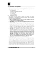
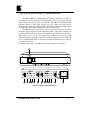
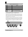
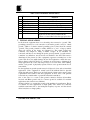
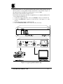
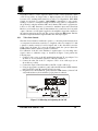
KRAMER ELECTRONICS, Ltd.
USER MANUAL
VIDEO ISOLATORS
Models:
OC-1N
OC-2
OC-4
IMPORTANT: Before proceeding, please read paragraph entitled
"Unpacking and Contents"
KRAMER ELECTRONICS, LTD.
P/N: 2900-008001
Section
1
1.1
2
3
3.1
4
5
6
7
8
8.1
9
10
10.1
10.2
10.3
11
12
12.1
12.2
13
Figure
1
2
3
4
5
Table
1
2
3
4
Table Of Contents
Name
Page
INTRODUCTION
2
Factors Affecting Quality of Results
2
HOW DO I GET STARTED?
2
UNPACKING AND CONTENTS
3
Optional Accessories
3
GETTING TO KNOW YOUR OC-1N VIDEO ISOLATOR 3
GETTING TO KNOW YOUR OC-2 VIDEO ISOLATOR
5
GETTING TO KNOW YOUR OC-4 VIDEO ISOLATOR
6
TYPICAL APPLICATIONS
7
INSTALLATION
9
Rack/Table Mounting
9
CONNECTING TO VIDEO DEVICES
9
USING THE MACHINES
9
Powering on the Machine
9
HF Level Control
9
Video Gain Control
10
TAKING CARE OF YOUR MACHINE
11
TROUBLESHOOTING
11
Power and Indicators
11
Video Signal
11
Specifications
12
Limited Warranty
12
List Of Illustrations
OC-1N Front/Rear Panel Features
OC-2 Front/Rear Panel Features
OC-4 Front/Rear Panel Features
Typical Ground Isolation Setup
Calibrating and adjusting the OC-1N
List Of Tables
OC-1N Front/Rear Panel Features
OC-2 Front/Rear Panel Features
OC-4 Front/Rear Panel Features
Cable Degradation/Attenuation List
KRAMER ELECTRONICS, LTD.
Page
4
5
6
8
10
Page
4
6
7
9
1
1. INTRODUCTION
Congratulations on your purchase of this Kramer Electronics Video Isolator.
Since 1981 Kramer has been dedicated to the development and manufacture of high
quality video/audio equipment. The Kramer line has become an integral part of
many of the best production and presentation facilities around the world. In recent
years, Kramer has redesigned and upgraded most of the line, making the best even
better. Kramer’s line of professional video/audio electronics is one of the most
versatile and complete available, and is a true leader in terms of quality,
workmanship, price/performance ratio and innovation. In addition to the Kramer line
of high quality switchers, such as the one you have just purchased, Kramer also
offers a full line of high quality distribution amplifiers, processors, interfaces,
controllers and computer-related products. This manual includes configuration,
operation and option information of the Kramer OC-1N, OC-2 and OC-4 Video
Isolators for the video professional.
1.1
Factors Affecting Quality of Results
There are many factors affecting the quality of results when signals are transmitted
from a source to an acceptor as described below:
FACTOR
Connection cables
Sockets and connectors
of the sources and
acceptors
Amplifying circuitry
Distance between
sources and acceptors
Interference from
neighboring electrical
appliances
EFFECT
Low quality cables are susceptible to interference; they degrade signal
quality due to poor matching and cause elevated noise levels. They
should therefore be of the best quality.
So often ignored, they should be of highest quality, since "Zero Ohm"
connection resistance is the target. Sockets and connectors also must
match the required impedance (75ohm in video). Cheap, low quality
connectors tend to rust, thus causing breaks in the signal path
Must have quality performance when the desired end result is high
linearity, low distortion and low noise operation
Plays a major role in the result. For long distances between sources
and acceptors, special measures should be taken in order to avoid
cable losses. These include using higher quality cables or adding line
amplifiers.
These can have an adverse effect on signal quality. Balanced audio
lines are less prone to interference, but unbalanced audio should be
installed far from any mains power cables, electric motors,
transmitters, etc. even when the cables are shielded
2. HOW DO I GET STARTED?
The fastest way to get started is to take your time and do everything right the first
time. Taking 15 minutes to read the manual may save you a few hours later. You
don’t even have to read the whole manual. So if a certain section doesn’t apply to
you, you don’t have to spend your time reading it.
KRAMER ELECTRONICS, LTD.
2
3. UNPACKING AND CONTENTS
The items contained in your Kramer accessory package are listed below. Please save
the original box and packaging materials for possible future transportation and
shipment of the machine.
Video Isolator
Kramer concise product catalog/CD
AC power cable
4 rubber feet
This user Manual
3.1
Optional Accessories
The following accessories, which are available from Kramer, can enhance
implementation of your machine. For information regarding cables and additional
accessories, contact your Kramer dealer.
BNC "Y" Connector - Used for looping purposes and splits the incoming signal
to enable connection of an additional machine.
Rack Adapter - Used to install smaller size machines in a standard 1U rack. One
or more machines may be installed on each adapter.
VIDEO TESTER - A new, unique, patented, indispensable tool for the video
professional, the video Tester is used to test a video path leading to/from an
amplifier. By pressing only one touch switch it can trace missing signals,
distinguish between good and jittery (VCR sourced) signals, and identify the
presence of good signals. Whenever a video signal is missing, because of bad
connections, cable breaks or faulty sources, the video Tester is all you need.
VM-5ARII – for distributing the isolated outputs of the OC machines. The
KRAMER VM-5ARII is an ultra-high bandwidth, Video Audio Distribution
Amplifier designed for studio and other demanding applications. The VM-5ARII
splits a single input source into five identical outputs with no discernible signal
degradation. The machine has looping inputs for system extension. The user can
adjust video gain and EQ. control as well as audio L and R levels externally. The
VM-5ARII allows AC/DC video input coupling selection and has a video
termination switch simplifying looping. The machine operates in Audio-followVideo mode, and has fully buffered, Broadcast level, audio stereo outputs.
4. GETTING TO KNOW YOUR OC-1N VIDEO ISOLATOR
The KRAMER OC-1N is a high quality Video Isolator unit, designed for broadcast
and industrial studio applications. In contradiction to the commercially available
machines, which are based on non-linear transformers, with poor frequency
response, the OC-1N is designed around a state-of-the-art active opto-isolator device
with extremely high linearity and very wide frequency response. The OC-1N allows
the user to select which GROUND becomes floating - input, output, both or none,
using rear panel switches. The OC-1N eliminates problems related to video hum,
ground loops, DC offsets and a host of interfering factors, which upset video picture
KRAMER ELECTRONICS, LTD.
3
quality. The OC-1N is housed in a compact enclosure; making it suitable for use in
the most space-limited places. The machine allows external fine-tuning of output
video levels and frequency response compensation via trimmers accessible from the
rear panel. Front/Rear panel features of the OC-1N are described in Figure 1 and
Table 1.
Figure 1: OC-1N front/back features
Table 1: OC-1N Front/Rear Panel Features
No.
Feature
1.
2.
3.
Power Switch
IN BNC connector
Amp trimmer
4.
5.
6.
7.
8.
9.
IN Gnd. pushbutton
OUT Gnd. pushbutton
HF trimmer
Gain trimmer
OUT BNC connector
Power Connector
Function
Illuminated switch: supplies power to the unit.
Video input.
Controls the video level of the input signal (to be used
only if Gain trimmer had insufficient effect!).
When released "floats" the input signal.
When released "floats" the output signal.
Controls cable equalization of the video output.
Controls the level of the video output.
Video output.
A 3-prong AC connector allows power to be supplied to
the unit, directly underneath this connector, a fuse
holder houses the appropriate fuse.
KRAMER ELECTRONICS, LTD.
4
5. GETTING TO KNOW YOUR OC-2 VIDEO ISOLATOR
The Kramer OC-2 is a high quality, dual channel optical video isolator. It
is designed to provide complete isolation between video sources and receiving
devices such as monitors, projectors, and VCR’s. The OC-2 can eliminate many
problems related to video hum, ground loops, DC offsets and other factors,
which interfere with video picture quality. Rear panel controls allow fine-tuning
of output video levels and frequency response of both channels.
The OC-2’s active opto-isolator circuits offer linear response and wide
frequency range compared to transformer-based units. Rear panel switches are
provided which allow the user to select which ground will become floating input, output, both, or none. The channels are completely isolated from each
other. It is rugged, dependable, and is housed in a compact enclosure which can
also be rack mounted using an optional rack adaptor which holds two units in
one vertical rack space.
Front/Rear panel features of the OC-2 are described in Figure 2 and Table 2.
Figure 2: OC-2 front/back features
KRAMER ELECTRONICS, LTD.
5
Table 2: OC-2 Front/Rear Panel Features
No.
10.
11.
12.
13.
14.
15.
16.
17.
Feature
Power Switch
IN BNC connector
IN Gnd. pushbutton
OUT Gnd. pushbutton
HF trimmer
Gain trimmer
OUT BNC connector
Power Connector
Function
Illuminated switch: supplies power to the unit.
Video input of each channel.
When released "floats" the input signal.
When released "floats" the output signal.
Controls cable equalization of the video output.
Controls the level of the video output.
Video output.
A 3-prong AC connector allows power to be
supplied to the unit, directly underneath this
connector, a fuse holder houses the appropriate fuse.
6. GETTING TO KNOW YOUR OC-4 VIDEO ISOLATOR
The Kramer OC-4 is a high quality, quad channel optical video isolator. It is
designed to provide complete isolation between video sources and receiving devices
such as monitors, projectors, and VCR’s. The OC-4 can eliminate many problems
related to video hum, ground loops, DC offsets and other factors, which interfere
with video picture quality. Rear panel controls allow fine-tuning of output video
levels and frequency response of both channels.
The OC-4’s active opto-isolator circuits offer linear response and wide frequency
range compared to transformer-based units. Rear panel switches are provided which
allow the user to select which ground will become floating - input, output, both, or
none. The channels are completely isolated from each other. It is rugged,
dependable, and is housed in a 19”, 1U enclosure for installation in a standard 19”
rack. Front/Rear panel features of the OC-4 are described in Figure 3 and Table 3.
Figure 3: OC-4 Front/Rear Panel Features
KRAMER ELECTRONICS, LTD.
6
Table 3: OC-4 Front/Rear Panel Features
No.
18.
19.
20.
21.
22.
23.
24.
25.
Feature
Power Switch
IN BNC connector
IN Gnd. pushbutton
OUT Gnd. pushbutton
HF trimmer
Gain trimmer
OUT BNC connector
Power Connector
Function
Illuminated switch: supplies power to the unit.
Video input of each channel.
When released "floats" the input signal.
When released "floats" the output signal.
Controls cable equalization of the video output.
Controls the level of the video output.
Video output.
A 3-prong AC connector allows power to be
supplied to the unit, directly underneath this
connector, a fuse holder houses the appropriate fuse.
7. TYPICAL APPLICATIONS
In all electronic equipment there’s is a electrical point connected to “ground”. This
grounding point may be a real connection to the mains ground or may be “virtual
ground”, which is a relative internal grounding point, isolated from the external
“ground”. The ground potential is usually defined as a "zero" voltage potential,
where all voltages in the device are referenced to. The virtual ground may
sometimes very dangerous, riding on Mains voltages. If two machines are
connected, and they are not sharing the precise ground potential, “ground currents”
sometimes very hazardous, may flow from one machine to the other. This creates a
disturbance in the picture (in video equipment), apparent as running bars on the
screen. This flow even might damage the involved equipment or harm the users.
This problem is called "Ground Loop", and there are several ways to eliminate it. In
many applications the source and acceptor may not be even in the same building,
and the “real ground” is physically separate. In those cases ground current flow is
unavoidable.
In other applications ground separation may be obligatory by law, such as in medical
applications. Video equipment is widely used in the medical field for physical
monitoring and surgery. Endoscopes are used instead of interrogative surgery, using
sophisticated video cameras and other equipment. In those cases, total galvanic
isolation from potential mains or ground flow hazards is mandatory.
One of the ways is to assure a firm ground connection between all machines
involved and Mains ground only if a common ground is available. For medical
applications, this solution is not sufficient.
Another solution is to separate the grounds of the machines by transformers. This is
not suitable for video applications, as high quality video cannot use commonly
available transformers due to the inadequate frequency response, and the adverse
effect it may have on image quality.
KRAMER ELECTRONICS, LTD.
7
The preferred way is to use special ground-isolation devices such as the OC-1N. In
this way, there is a total galvanic isolation between the source and the acceptor, as
the signal isolation is mediated by optical means - by a ray of light.
This system is demonstrated by figure 4 below.
Perform the following steps (the same is applicable for two channels with the OC-2
or four channels with the OC-4):
1. Connect the output of the video source to the IN BNC connector of the OC-1N.
2. Connect the OUT BNC connector of the OC-1N to the inputs of a video
acceptor.
3. Operate the source, acceptor and the OC-1N.
4. Use the GAIN, HF, GND controls of the OC-1N as necessary.
Figure 4: A typical ground isolation setup
KRAMER ELECTRONICS, LTD.
8
8. INSTALLATION
8.1
Rack/Table Mounting
The OC-1N and the OC-2 can be rack mounted using an optional special adapter
(see section 3.1). The OC-4 may be directly rack mounted, as it is already 19” sized.
The devices do not require any specific spacing for ventilation above or below the
units. To mount the machine, simply place the unit'
s ears against the rack rails of
your rack and insert standard screws through each of the four corner holes.
9. CONNECTING TO VIDEO DEVICES
Video sources and output devices may be connected to the OC-1N/OC-2/OC-4
through the BNC type connectors located on the back of the unit. Please keep in
mind that the output signal format will match that of the input signal format. The
signal supported by the various models is Composite video.
10. USING THE MACHINES
10.1
Powering on the Machine
NOTES
1. The machine should only be powered on, after all connections are completed,
and all source devices have been powered on. Do not attempt to connect or
disconnect any video to the machine while it is powered on!
2. The socket-outlet should be near the equipment and should be easily accessible.
To fully disconnect equipment, remove power cord from socket.
3. Press the toggle switch on the far-left front panel to the up position. The toggle
switch becomes lit.
4. Operate the sources and acceptors.
10.2
HF Level Control
HF Control function enables the operator to compensate for degradation of the video
signal in high frequencies due to long or non-standard cables. Popular cables such as
the RG-59, RG-11 or the RG-179 signal cause degradation/attenuation as shown in
the following Table 4:
Table 4: Cable Degradation/Attenuation List
CABLE
TYPE
RG-59
RG-11
RG-179
LENGTH
FREQUENCY
ATTENUATION
100 meter
100 meter
100 meter
100 meter
100 meter
100 meter
10MHz
100MHz
10MHz
100MHz
10MHz
100MHz
3.6dB
11dB
2.2dB
7.5dB
8dB
30dB
KRAMER ELECTRONICS, LTD.
9
Degradation and loss of video signal are mainly a result of stray capacitance, which
occur in long cables. As longer cables or higher frequency are used, the problem
becomes worse, resulting in fine detail loss as well as color degradation. When RGB
signals are involved for example, (200-300MHz), degradation is even greater,
leading to a total loss of sharpness at high resolution. It is possible to compensate for
the problem by using the machines'HF control trimmer. HF control is performed as
follows: A Color Bar Generator is connected to machines'input and a Waveform
Monitor (or an Oscilloscope with 75ohm termination) is connected to the long cable
output. A known color bar signal is applied to the amplifier’s input and compared to
the signal monitored at the far side. The operator adjusts the HF trimmer until the
measured output Chrominance signal matches that of the input signal.
10.3
Video Gain Control
The Gain Control function enables the operator to control the picture intensity level
or compensate for distortions caused by too long/short cables, for example. Too dark
a picture is usually caused by low-level signals and on the other hand, excessive
levels "burn" the picture. To correct the incoming signal, the operator adjusts the
GAIN trimmers until a satisfactory picture is achieved.
If a calibration of the OC series machines is required due to low incoming video
signal, connect a calibration setup, as described in Figure 5 and perform the
following steps:
1. Connect a video source to the OC machine input through "T" type adapter. You
should do it on every channel, if needed, of the OC-2 and OC-4.
2. Connect the other side of the "T " adapter to CH. 1 of an oscilloscope (use as
short cable as possible).
3. Connect the output of the OC machine to the CH. 2 of the oscilloscope.
4. Using an appropriate screwdriver, gently adjust the HF and the GAIN trimmers
until a both CH. 1 and CH. 2 measured levels are equal.
5. If signal level is still insufficient, gently adjust the AMP trimmer (of the OC-1N
only) until satisfactory level and hence proper picture is achieved.
Figure 5: Calibrating and adjusting the OC-1N
KRAMER ELECTRONICS, LTD.
10
11. TAKING CARE OF YOUR MACHINE
Do not locate your machine in an environment where it is susceptible to dust or
moisture. Both of these may damage the electronics, and cause erratic operation or
failure. Do not locate your machine where temperature and humidity may be
excessive. Doing so may also damage the electronics, and cause erratic operation or
failure of your machine. Do not clean your machine with abrasives or strong
cleaners. Doing so may remove or damage the finish, or may allow moisture to build
up. Take care not to allow dust or particles to build up inside unused or open
connectors.
12. TROUBLESHOOTING
NOTES
Please note that if the output signal is disturbed or interrupted by very strong external
electromagnetic interference, it should return and stabilize when such interference ends. If not, turn
the power switch off and on again to reset the machine.
12.1
Power and Indicators
Problem
No Power
Remedy
1.
2.
3.
12.2
Confirm that the rocker switch is in the “ON” position, and that the
red LED is illuminated.
Confirm that power connections are secured at the machine and at
the receptacle. Make sure the mains receptacle is active.
If still there is no power, remove power cord from AC outlet and
then using a flat head screwdriver, remove the fuse holder located
directly below the power connector on your machine. Confirm that
the fuse is good by looking for the wire connected between the ends
of the fuse. If the wire is broken, replace the fuse with another, with
the same rating.
Video Signal
Problem
No video at the
output device
Remedy
1.
2.
3.
Video level is too
high or too dim.
1.
2.
Confirm that your source and output devices are powered on and
connected properly. The input of your machine should be of an
identical signal format at the output of your source. Signals at the
output of your machine should be of an identical signal format as at
the input of your display.
Confirm that any other device in the signal path have the proper input
and/or output selected.
Use the Video Tester to test the video path leading to/from your
machine (see section 3.1 " Video Tester").
Verify that the lines are well matched through 75ohm impedances,
otherwise it results in a video level that is too high or too dim.
Confirm that the connecting cables are of high quality and properly
inserted.
KRAMER ELECTRONICS, LTD.
11
13. SPECIFICATIONS
OC-1N
OC-2
OC-4
Video Bandwidth
1 video 1Vpp/75ohm 2x1 video
on a BNC
1Vpp/75ohm on
BNCs
1 video 1Vpp/75ohm 2x1 video
on a BNC
1Vpp/75ohm on
BNCs
20MHz, -3dB
20MHz, -3dB
4x1 video
1Vpp/75ohm on
BNCs
4x1 video
1Vpp/75ohm on
BNCs
20MHz, -3dB
Non Linearity
0.21dB
0.21dB
0.21dB
Video S/N Ratio
69dB
69dB
69dB
Dimensions (W, D, H)
16.5 x 12 x 4.5 (cm)
6.5" x 4.7" x 1.8"
22 x 18 x 4.5cm
(8.7" x 7" x 1.8”).
Weight
0.72kg. (1.6lbs.)
Approx.
2.3VA
1.3 kg. (2.9 lbs.)
Approx.
6 VA.
19” (W) x 7”(D) x
1U (H), rack
mountable.
3.5 kg. (7.8 lbs.)
Approx.
14 VA.
230VAC, 50/60 Hz,
(115VAC, U.S.A.)
230VAC, 50/60 Hz,
(115VAC, U.S.A.)
230VAC, 50/60 Hz,
(115VAC, U.S.A.)
Input(S)
Output(S)
Power Consumption
Power Source
LIMITED WARRANTY
Kramer Electronics (hereafter Kramer) warrants this product to be free from defects in material
and workmanship under the following terms.
HOW LONG IS THE WARRANTY
Labor and parts are warranted for three years from the date of the first customer purchase.
WHO IS PROTECTED
Only the first purchase customer may enforce this warranty.
WHAT IS COVERED AND WHAT IS NOT COVERED
Except as below, this warranty covers all defects in material or workmanship in this product. The
following are not covered by the warranty:
1. Any product, which is not distributed by Kramer or which, is not purchased from an
authorized Kramer dealer. If you are uncertain as to whether a dealer is authorized, please
contact Kramer at one of the agents listed in the web site www.kramerelectronics.com.
2. Any product, on which the serial number has been defaced, modified or removed.
3. Damage, deterioration or malfunction resulting from:
a)
b)
Accident, misuse, abuse, neglect, fire, water, lightning or other acts of nature.
Unauthorized product modification, or failure to follow instructions supplied with the
product.
KRAMER ELECTRONICS, LTD.
12
c)
d)
e)
f)
g)
Repair or attempted repair by anyone not authorized by Kramer.
Any shipment of the product (claims must be presented to the carrier).
Removal or installation of the product.
Any other cause, which does not relate to a product defect.
Cartons, equipment enclosures, cables or accessories used in conjunction with the
product.
WHAT WE WILL PAY FOR AND WHAT WE WILL NOT PAY FOR
We will pay labor and material expenses for covered items. We will not pay for the following:
1.
Removal or installations charges.
2.
Costs of initial technical adjustments (set-up), including adjustment of user controls or
programming. These costs are the responsibility of the Kramer dealer from whom the
product was purchased.
3.
Shipping charges.
HOW YOU CAN GET WARRANTY SERVICE
1.
2.
3.
To obtain service on you product, you must take or ship it prepaid to any authorized Kramer
service center.
Whenever warranty service is required, the original dated invoice (or a copy) must be
presented as proof of warranty coverage, and should be included in any shipment of the
product. Please also include in any mailing a contact name, company, address, and a
description of the problem(s).
For the name of the nearest Kramer authorized service center, consult your authorized
dealer.
LIMITATION OF IMPLIED WARRANTIES
All implied warranties, including warranties of merchantability and fitness for a particular
purpose, are limited in duration to the length of this warranty.
EXCLUSION OF DAMAGES
Kramer’s liability for any defective products is limited to the repair or replacement of the product
at our option. Kramer shall not be liable for:
1.
2.
Damage to other property caused by defects in this product, damages based upon
inconvenience, loss of use of the product, loss of time, commercial loss; or:
Any other damages, whether incidental, consequential or otherwise. Some countries may not
allow limitations on how long an implied warranty lasts and/or do not allow the exclusion or
limitation of incidental or consequential damages, so the above limitations and exclusions
may not apply to you.
This warranty gives you specific legal rights, and you may also have other rights, which vary from
place to place.
NOTE: All products returned to Kramer for service must have prior approval. This may be
obtained from your dealer.
KRAMER ELECTRONICS, LTD.
13
NOTICE
This equipment has been tested to determine compliance with the requirements of:
EN-50081:
EN-50082:
CFR-47
"Electromagnetic compatibility (EMC);
generic emission standard.
Part 1: Residential, commercial and light industry"
"Electromagnetic compatibility (EMC) generic immunity standard. Part 1:
Residential, commercial and light industry environment".
FCC Rules and Regulations:
Part 15- “Radio frequency devices:
Subpart B- Unintentional radiators
CAUTION
Servicing the machines can only be done by an authorized Kramer technician. Any
user who makes changes or modifications to the unit without the expressed approval
of the manufacturer will void user authority to operate the equipment.
Use the supplied power cord to feed power to the machine.
Please use recommended interconnection cables to connect the machine to other
components.
KRAMER ELECTRONICS, LTD.
14
For the latest information on our products and a list of Kramer
distributors, visit our Web site: www.kramerelectronics.com.
Updates to this user manual may be found at
http://www.kramerelectronics.com/manuals.html.
We welcome your questions, comments and feedback.
Kramer Electronics, Ltd.
Web site: www.kramerelectronics.com
E-mail: [email protected]
P/N: 2900-008001 REV 2